
|

|
Forum Index : Electronics : 8 KW Inverter Build
| Author | Message | ||||
| Warpspeed Guru Joined: 09/08/2007 Location: AustraliaPosts: 4406 |
The problem is that the transformer primary probably has sufficient inductance at 50Hz, but at 20 Khz it looks more like a giant capacitor, because the self resonant frequency of the transformer is very likely to be well below 20 Khz. Its actually the self resonant secondary that is the problem, but that just reflects back into the primary. Not much you can do about the transformer itself. It would work great if were to be run at 50 Hz, but is a disaster trying to drive it at frequencies about 400 times higher than that. The solution is to add some series inductance from a choke that has a very high self resonant frequency, so it still looks like an inductor at 20 Khz and well beyond 20 Khz, but has a very low impedance (and resulting low loss) at 50 Hz. So at 20 Khz the inverter bridge sees only the choke, the transformer primary looking pretty much like a dead short at 20 Khz. That is very good that the transformer has a high attenuation at 20 Khz. At 50 Hz the choke should offer minimal series loss, and the transformer primary acts as if it were driven by a 50 Hz sine wave, which is actually pretty much what happens. So basically the series choke turns the 20 Khz PWM into a 50Hz sine wave that the transformer will be happy with. The bridge will be happy too, the ripple current through the choke should be roughly in the region of 25% to 30% at full power. That would be a fairly typical design objective. At the bridge side of the choke you should see a fast clean switching PWM square wave voltage. On the transformer side of the choke, typically a sine wave with just some slight high frequency ripple on it. Its just like designing a 5Kw buck regulator, because that is really how it should be working. A buck regulator modulated by a sine wave to create an "almost" dc voltage which is going up and down like a yo-yo at 50 Hz in a carefully controlled sine wave shape. You can get away with murder with PWM at fairly low power. But as you scale up the power there is far less tolerance for something that is a bit Mickey Mouse and not properly designed. Cheers, Tony. |
||||
Madness Guru Joined: 08/10/2011 Location: AustraliaPosts: 2498 |
Hi Klaus, My dead time is Oztules standard at the minimum, I have thought about trying a longer setting again to how that goes. My big Toroid is 70mm welding wire, I have found it to behave not that much differently to my single core test toroid. But I can't rule it out that there is enough difference to cause issues. The test Toroid has about 24mm square on it, I am in the process of making a new single core. I am planning to put around 35mm on it. I am going to try cutting enough lengths of enamelled copper wire and see if I can twist them to make like a normal multi-strand cable and then wind that on. This will end up going in a case with the small power board above as a backup and to run diverted power to my hot water system. There are only 10 types of people in the world: those who understand binary, and those who don't. |
||||
Madness Guru Joined: 08/10/2011 Location: AustraliaPosts: 2498 |
Thanks again Warp for your insight. Looking at either side of the choke with a CRO is very different like you say one side you can see the SPWM and the other just a 50HZ sinewave. White man's magic at it's finest! There are only 10 types of people in the world: those who understand binary, and those who don't. |
||||
| Tinker Guru Joined: 07/11/2007 Location: AustraliaPosts: 1904 |
Thanks for that info Gary, now I have another question  . .With your latest drive circuit, using TIP41/42C's as per Solar Mike's diagram, the upper pair with the floating 12V supply does not show the common tied back to VS (pin 5) on the IR2110 chip. I think it should be, is yours? The lower pair has the common tied to ground of course. Also, what value gate resistor did you use - it shows 10 Ohm for 5xHY4008 -. I think for only 4 x HY4008 these should be 8R2? I am thinking changing my PCB to include those boost drivers since they work for you. Klaus |
||||
| Warpspeed Guru Joined: 09/08/2007 Location: AustraliaPosts: 4406 |
Indeed it is ! Once you understand the magic of how it is all supposed to work together, and gain that insight, its only then a small step to figure out what specific optimum parts may be required. Another little known secret to all of this, is to resonate the transformer secondary at about 1.5 times the mains frequency with a suitably rated capacitor right across the transformer secondary. That will provide enormous attenuation of any residual PWM. That would cause instant death to the bridge without our faithful series choke in the primary. But with the series choke, plus capacitor across the secondary we can get extremely high attenuation at 20 Khz, and get a very clean output. If the secondary is made to have a resonance very close to 50 Hz, you could get a giant destructive resonant buildup of energy with zero output load connected, which would be a disaster. But an interesting thing happens at around 75 Hz. Any stored resonant energy cannot build up to dangerous levels, because if it tries, it finds itself out of phase with the next following cycle. So its kind of self damping at 50 Hz. Anything between about 70Hz and 85 Hz should work perfectly well, so the nearest standard capacitor value should be fine. It will probably end up being a few Microfarads. Cheers, Tony. |
||||
Madness Guru Joined: 08/10/2011 Location: AustraliaPosts: 2498 |
Klaus the control board remains unchanged on my latest PCB with the TIP 41c/42c so each bridge is connected back to it's IR2110 VS pin. It only changes at the gate drive circuit with the 20 ohm resistor onwards as per Mikes diagram. On the power board, I used the same circuit Oztules uses on the control board to produce 12V. Mine has the same circuit as Mike provided and the same value resistors. I did include the snubbers as I have always had 3W 47R and 3KV 103 cap in series from each side of the bridge to ground and +48V, so 4 snubbers in total. As for changing the resistors for FETs I have no idea, I had it running initially with 1 HY4008W on each leg for testing, then 3 and then 5 all with 10 ohm gate resistors. It gave the same result on each short test at idle and under load. They run very cool and as Oztules mentioned he can start a 5KW motor with 4 on each leg. I have had it running for 6 days now, so far I have not done a really hard test but the fans very rarely startup to cool the heatsink. Apart from a short on one of the transistors which showed up on my initial test, it has worked without missing beat. What I have found very useful for testing I put 2 pins on a control board to connect 12V to the output of the transformer with a jumper wire as needed. This fools the board into running continuously with no AC VFB. Then you can connect the output with another jumper to each gate drive and test them individually. This was done with no caps on the power board and power connected through a resistor, that way you won't blow a FET if something is wrong. There are only 10 types of people in the world: those who understand binary, and those who don't. |
||||
| Tinker Guru Joined: 07/11/2007 Location: AustraliaPosts: 1904 |
Thanks for that Tony. Unfortunately math was never a strong point in my education. I assume putting a capacitor across the secondary creates a parallel resonance. Looking at the formula for that and seeing a square root symbol my brain immediately switched off  . .Could you or anybody re arrange the formula so that C (capacitor) = ...... I can then insert the 75Hz where appropriate and my 93 mH secondary inductance and get the correct capacitor value with the appropriate calculator strokes. This sure would beat a lot of experimenting. Klaus |
||||
Madness Guru Joined: 08/10/2011 Location: AustraliaPosts: 2498 |
I found the cause of the small waves within the waveform as shown here. 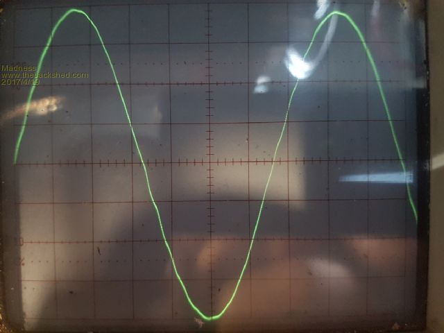 It was the old Trace inverter, I turned it off and the big Inverter reduced the noise it makes to about 1/3 and the wave smoothed out completely running at 350W. So I tried the small Ozinverter at idle and with load and it no effect on the other inverter. There are only 10 types of people in the world: those who understand binary, and those who don't. |
||||
| Warpspeed Guru Joined: 09/08/2007 Location: AustraliaPosts: 4406 |
Klaus, I am mathematically challenged myself, especially before my first cup of coffee for the day (like right now) so here is a handy calculator. http://www.1728.org/resfreq.htm 75Hz + 93mH = 48.4uF. Loading down the output with 50uF sounds very dramatic, but in fact it forms a high impedance parallel resonant circuit, so amazingly the loading across the inverter output ends up being absolutely minimal at 75Hz and only slight at 50 Hz. What you need is one of those white 50uF 240 volt rated motor starting capacitors. http://www.ebay.com.au/sch/i.html?_from=R40&_trksid=p2380057.m570.l1313.TR1.TRC0.A0.H0.X50uF.TRS0&_nkw=50uF&_sacat=0 *edit* Do not fit this capacitor until you first have a series choke in the primary ! Cheers, Tony. |
||||
Madness Guru Joined: 08/10/2011 Location: AustraliaPosts: 2498 |
Klaus according to this calculator 50 microfarad and 93.43 mH will resonate at 73hz. There are only 10 types of people in the world: those who understand binary, and those who don't. |
||||
| Warpspeed Guru Joined: 09/08/2007 Location: AustraliaPosts: 4406 |
Yup, that should do nicely. Last night I thought a bit more about a suitable choke, and Klaus already has something that should probably come very close. 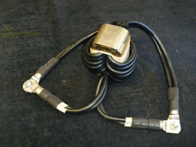 Its absolutely vital that the two windings need to be phased properly. Its supposed to be a centre tapped choke NOT a common mode transformer. Think of it as a flattened toroid. Wind all the turns in the same direction through the centre hole so each winding has a start and a finish. 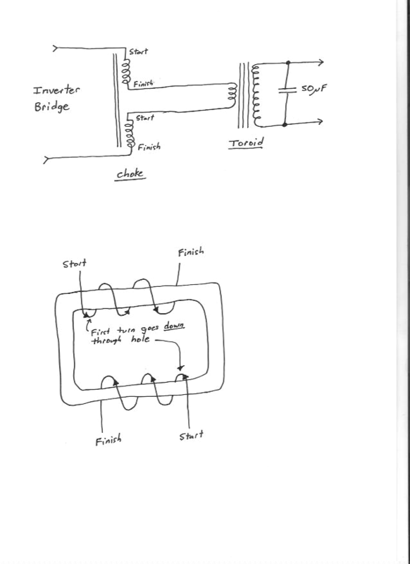 As a rough guess to begin, I would think about six to eight turns on each side might be about right as a first attempt. More on this later. Cheers, Tony. |
||||
Madness Guru Joined: 08/10/2011 Location: AustraliaPosts: 2498 |
That is effectively the same as the one I made with the Ferrite ring yesterday. But with that big ring I had to use only 3 turns to get a good waveform. There are only 10 types of people in the world: those who understand binary, and those who don't. |
||||
| Warpspeed Guru Joined: 09/08/2007 Location: AustraliaPosts: 4406 |
O/k here is an odd assortment of what we might need, what I have discovered so far, and some speculation......... Assuming we are talking about roughly a 5Kw inverter running at 48 volts and with 20 Khz PWM. That will be working at around 100 amps input current. Our PWM will be swinging from 0% (off all the time) to 100% (on all the time). In either case the choke will see only a dc current, as the PWM is not actually switching under those conditions. The choke will be working hardest at 50% duty cycle, where the peak to peak ac ripple current will be highest. So if we wanted a 30% peak to peak ripple current at 50% duty cycle, we need sufficient inductance to do that. So our minimum inductance requirement will be a 30 amp (30% of 100A) change in current, with 48 volts applied, over 25uS (50% of 20Khz period). Minimum inductor = 48v x 25uS divided by 30A = 40 uH So something a bit larger than 40uH would be about right. Now looking at one of those funny looking chokes fitted to grid tie inverters, and going through the same maths, we might start with a 2.5Kw inverter running at around 250 volts with an input current of perhaps 10 amps. Minimum inductor = 250v x 25uS divided by 3 amps = 2,083 uh minimum. The 3amps comes from 30% of our 10 amp dc input current. What we actually find fitted is typically about a 2.8 to 3mH choke which is comfortably above our required minimum. To achieve something similar we might need about 60uH. I tested one of these funny grid tie chokes and found that it had two windings each of about 42 turns, and it reached magnetic saturation at just over 30 amps. In operation the dc input current could be around 10 amps, but the PEAK current will be closer to 14 amps. So its designed to run comfortably below the 30 amps where it saturates, something that must never happen. If we salvage one of these cores, and use it as is, with its large air gap, and stip off all the turns (as Klaus has already done) we might have something we can use. If the original choke has about 3,000uH and 84 turns, how many turns might we need to get roughly 60 uH ? Inductance is proportional to turns squared so we can calculate the inductance of only one turn by dividing 3000uH by 84 squared and get 0.425 uH for one turn. If we rewind it to have 6 + 6 turns, we get 12 turns total. And twelve turns squared x 0.425uH per turn = 61.2 uH pretty much ideal. 8+8 turns would give us 109uH, heaps ! Now our original magnetic saturation occurred at 30 amps with 84 turns. And saturation is proportional to ampere turns. works out to 2,520 ampere turns. With 6+6 turns we saturate at 210 amps. With 8+8 turns we saturate at 157 amps which is getting dangerously low for our 100 amp inverter that might draw 140 amp peaks. So all things considered about 6+6 or 7+7 turns might be a good first guess. Looking at the core with the original winding removed, the rectangular hole through the core is 20mm x 70mm. With a bit of luck we should be able to just squeeze seven plus seven turns of round cable in there (maybe) if the outside diameter is no more than 10mm. I have not done this, but that would be my first attempt at a 5Kw 48 volt choke. Cheers, Tony. |
||||
| Warpspeed Guru Joined: 09/08/2007 Location: AustraliaPosts: 4406 |
You are on the right track. But I recommend you try rewinding a grid tie choke as above. You can wind it with thinner wire and say 7+7 turns just to try for starters at lower power and see how that goes. Then try resonating your transformer to 75 Hz. If that all works, then you can get more serious and try to stuff as much copper into the choke that will fit. Its going to be difficult, because those chokes are really only big enough for the original power level with a big safety margin. For higher power we can probably use two of those grid tie chokes if necessary. Cheers, Tony. |
||||
| Tinker Guru Joined: 07/11/2007 Location: AustraliaPosts: 1904 |
Thanks guys,, it appears the capacitor I used was only 1/10th of what is required. But I do recall oztules is not using a big capacitor across the secondary and apparently getting away with it. Yes that fine laminated choke has a big air gap, about 1.6mm or so. I have now taken off the windings shown in the picture above but the suggestion of using thinner wire for testing is on my list now. Klaus |
||||
| Warpspeed Guru Joined: 09/08/2007 Location: AustraliaPosts: 4406 |
The large capacitor is only really needed to remove the last traces of any high frequency PWM. If the self resonant frequency of the transformer is already fairly low, that may put some visible bumps into the waveform, by making it very low, (say 75 Hz) that should remove any bumps caused by transformer self resonance. Cheers, Tony. |
||||
Madness Guru Joined: 08/10/2011 Location: AustraliaPosts: 2498 |
Warp are the bumps you are referring to those that appear at zero crossing? as per this pic. 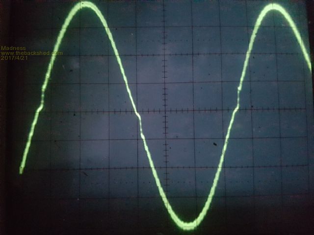 There are only 10 types of people in the world: those who understand binary, and those who don't. |
||||
| Warpspeed Guru Joined: 09/08/2007 Location: AustraliaPosts: 4406 |
I cannot find a really suitable picture on the internet, but this is a sinewave with one particular fairly high order harmonic added onto it. If there was a very strong transformer self resonance it might look something like that, with a higher frequency sine wave ripple superimposed on the 50Hz. 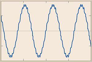 Cheers, Tony. |
||||
oztules Guru Joined: 26/07/2007 Location: AustraliaPosts: 1686 |
For reference, my transformer secondary winding seems to measure about 196mH..... substantially higher than Tinkers. ( this is yet another transformer.... the secondary is wound and sealed, waiting for primary) It is 120 turns of 2 in hand x 2mm diameter wire on two 1.5kw inspire cores of 44X65mm cross section each for 44x130mm total cross section for 5720mmsq or 2v/turn.. So 2 x 3.14 X 2=6.3mm sq..... so the primary for this one ( not yet wound ) will want to be about 50mmsq for balance... don't have any at the moment, so it will probably be 32mmsq. ( only 6 meters long, so that will probably run 100 amps no problems for a long time) Will be 2 x 16mmsq windings... better cooling too I guess. ( like the one in the previous picture blue and white x 16mmsq each) Not very scientific, but it seems to work just fine.... this must be about the tenth one, and they are all slightly different... depends how I feel at the time really... ie three cores from the aerosharps, or two from the inspire, but always now bring the hole up to 96mm or more for easy winding... thats the key to simple winding. Hope that provides some background to what I now generally run. .......oztules Village idiot...or... just another hack out of his depth |
||||
Madness Guru Joined: 08/10/2011 Location: AustraliaPosts: 2498 |
I have just wound a primary on a single core using the wire that was removed, I will get photos later. It saved me close to $100 to buy welding wire and only took an hour to prepare for winding on the core. What I did is measure out 19 lengths of the 8 metres required (1.1v per turn X 24 turns). I then tied the wires securely to a post got them as straight and parallel as practical. I put a small cable tie every 300 mm to keep them in place and made a clamp out of 2 pieces of pine with a hole drilled in the middle a little smaller than the combined wire diameter and clamped it onto the other end of the wire. Then I just pulled and twisted it until I got a good amount of twist on it. Then I wound it onto the toroid, the wire held together with the twist and was quite easy to bend around the corners. I have tested it and it runs fine, now I need to put some epoxy on it to keep everything stable and the job is done. 24 turns of 1.6 X 19 wires fitted nicely in the space available in the single core, I had to use a tyre lever to push open a gap for the last couple turns. So I now have a 38 square mm primary for next to no cost. Why did I use 19? Here is why and it ended up 8 mm diameter.  There are only 10 types of people in the world: those who understand binary, and those who don't. |
||||