|

|
Forum Index : Microcontroller and PC projects : Beta Testers Wanted
| Author | Message | ||||
| vasi Guru Joined: 23/03/2007 Location: RomaniaPosts: 1697 |
I see UEXT Olimex connector as a good solution for a network of I2C devices, serial comm. and one SPI device (up to 5 if nothing else is used). It can be a standard and there are already devices made for the bus. In my opinion, is better "designed" than the Mikroelektronika bus, and easier to use and to make the PCB board, easier to clamp connectors on the bus cable. Hobbit name: Togo Toadfoot of Frogmorton Elvish name: Mablung Miriel Beyound Arduino Lang |
||||
MicroBlocks Guru Joined: 12/05/2012 Location: ThailandPosts: 2209 |
i personally not like the uext, gadgeteer and grove systems. to many cables... they often require many connectors on the pcb, making it big, especially if you need only one. the reason i choose a 'backplane' or 'stackable' is that the cpu/mcu pcb needs only one connector. if you want to add 1 or 2 modules you just stack them, or if you not have enough room vertically you can put them next to eachother. you can even stack a module on another module. having a backplane also allows you to have support for other systems. pretty easy to add a uext or grove connector. the backplane can be a simple single sided board and can be made cheaply at home. Very effective to change your prototype in a nice looking product. Microblocks. Build with logic. |
||||
| viscomjim Guru Joined: 08/01/2014 Location: United StatesPosts: 925 |
Jeez, over 300 posts on this one!!!! |
||||
| vasi Guru Joined: 23/03/2007 Location: RomaniaPosts: 1697 |
In UEXT case, here is about a single (long) cable in many applications but yes, there can be many cables if required. In my opinion is a better system than the stackable one. Usually, the sensors are outside the main board. Here is the Mikroelektronika solution (stacks): 
Theboards have female connectors - that is bad as there is less endurance. Here is Olimex solution: 
Does not matter if is the main board or the sensor board, all of them have male connectors. The worn-able parts are on the removable/replaceable cable. This is what I consider design based on experience. Hobbit name: Togo Toadfoot of Frogmorton Elvish name: Mablung Miriel Beyound Arduino Lang |
||||
Grogster Admin Group Joined: 31/12/2012 Location: New ZealandPosts: 9310 |
...and it does not look like anyone has got sick of the thread yet. Still plenty of posts rolling in on this thread each day. Impressive. Smoke makes things work. When the smoke gets out, it stops! |
||||
| Alan68 Newbie Joined: 28/01/2013 Location: AustraliaPosts: 17 |
Hi, I've been having problems with Tera Term, I've got a GPS receiver connected to the MicroMite and when I have NMEA data scrolling up the screen on my laptop just slowing certain sentences after a few minutes Tera Term starts showing rubbish scrolling up the screen and Tera Term has to be closed and reopened. I was using a prolific PL3203 USB to serial TTL adaptor as it has a 3.3V output, I swapped it for an old FTDI adaptor, I found in the bottom of a box and it works well if plugged directly into my laptop, hubs seam to cause problems. I remembered someone saying program a MicroMite for a Maximite. I've connected a Duinomite to a MicroMite as com's 3 & 4 can work at 38400 baud Option break 4 Open "com3:38400" As #1 Do a$ = Inkey$ Print #1, a$; b$ = Input$(1,#1) Print b$; Loop COM3 can be found on the UEXT of a Duinomite The XMODEM command does not work. My laptop if running windows 8. |
||||
| robert.rozee Guru Joined: 31/12/2012 Location: New ZealandPosts: 2350 |
the above (garbage characters after a long run of printing data, PL3203) could perhaps be caused by characters too closely spaced together and the odd dropped BIT. if the terminal is set for 2 stop bits, while the micromite is set for 1 stop bit, and if the micromite is outputting data at full tilt, then there seems the chance for a bit error to slip in. how many stop bits does the micromite use when sending to the terminal? does it add any extra delay (or not) between characters sent? and at high baud rates, what is the error on the bit clock - how much can the internal oscillator wander? rob :-) |
||||
TassyJim Guru Joined: 07/08/2011 Location: AustraliaPosts: 6103 |
Alan68, If I understand you correctly, You have a GPS receiver connected to a uMite and when using a Duinomite to display the data, all is working OK. If you connect the uMite directly to the PC with a FTDI converter all works OK with TeraTerm. Connecting via a USB hub causes problems. Using a Prolific converter causes problems even when connected directly to the PC. There were a lot of Chinese clones of Prolific chips which were very troublesome. The FTDI converter should not have problems with hubs and the low power drain of the uMite should help with hubs also. Many of the 3.3V supplies available on USB-serial converters are very low current as the 3.3V regulator is internal to the main chip. From the FTDI FT232BL chip data sheet: "In some cases, where only a small amount of current is required (< 5mA) , it may be possible to use the in-built regulator of the FT232B to supply the 3.3v without any other components being required." You may have been overloading the Prolific (and FTDI) chip. Jim Edit: I strongly recommend using the 5V supply and running your own 3.3V regulator. I normally use the LM1117 but it has a high Quiescent Current (5mA) I have ordered some XC6206 (662K) with a 1uA Quiescent Current. This is the usual one found on I2C modules. VK7JH MMedit MMBasic Help |
||||
| Alan68 Newbie Joined: 28/01/2013 Location: AustraliaPosts: 17 |
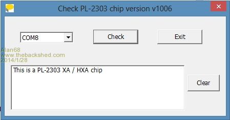
Hi TassyJim, I was originally powering the MicroMite from the Prolific 3.3V and thought that was the problem and now I'm using a separate 3.3V supply. The Prolific USB to serial interfaces work at 4800 & 9600 all day but not more than a few minutes at 38400 baud before it all turns to rubbish. Also when using the editor and doing a lot of going up and down the program causes Tera Term to display rubbish and loose it's way. I downloaded the latest drivers and there was a program to see if the Prolific IC is a copy 
It must be a combination of Windows 8, Prolific interface and 38400 baud. |
||||
Grogster Admin Group Joined: 31/12/2012 Location: New ZealandPosts: 9310 |
I had the rubbish too with the MM at 38k4, and I had to close and restart TT. This only happened to me, when I ran into that PIN number problem, and having reset MMBasic, the terminal then just gave me garbage ASCII symbols for anything typed. When I closed TT and reopened it, it was fine. I am also on Windows 8(Pro 32-bit), but I am using a native serial port on the back panel, not a USB adaptor thing. Also very much agree with Jim - you really do need to use an external regulator. My favourite reg these days tends to be the MCP1703 series. They make them in various preset voltages including 5v0(MCP1703-50) and 3v3(MCP1703-33). Up to 250mA output current, only 625mV dropout voltage, SMD package(I use the SOT-223 one), up to 16v input, and quiescent current of only 2 microamps! They are perfect for anything battery powered. NZ$0.62 each from Microchip Direct, or about NZ$2 each from Element-14 Smoke makes things work. When the smoke gets out, it stops! |
||||
palcal Guru Joined: 12/10/2011 Location: AustraliaPosts: 1873 |
I use these here Paul "It is better to be ignorant and ask a stupid question than to be plain Stupid and not ask at all" |
||||
Grogster Admin Group Joined: 31/12/2012 Location: New ZealandPosts: 9310 |
Well, that beats the 1703's 2uA. 
Ironically, I cracked open a wireless keyboard thing to fix it tonight, and what do I find? A regulator marked as 662K - that rang a bell in my head - I have heard of that description somewhere before........ Checked back here, and bugger me - exactly the same part! Smoke makes things work. When the smoke gets out, it stops! |
||||
MicroBlocks Guru Joined: 12/05/2012 Location: ThailandPosts: 2209 |
I often use the MCP1702. Very similar to the 1703 only a lower maximum input voltage of 13.2v. I sell them for 1USD. :) I use a motorcycle battery with 6.75-7v output. This keeps me isolated from the mains ,portable, and with the low drop regulators i can easily make 5v and 3.3v. I use it as my fixed voltages bench power supply. Microblocks. Build with logic. |
||||
Grogster Admin Group Joined: 31/12/2012 Location: New ZealandPosts: 9310 |
Yes, I love the MCP series regulators. They seem to work really well indeed. Granted, they don't have QUITE the standby current of the 662K's, but they are still pretty good at 2uA. The MCP's have a higher input voltage tolerance and output current though, so I guess everything is relative.  Smoke makes things work. When the smoke gets out, it stops! |
||||
| Geoffg Guru Joined: 06/06/2011 Location: AustraliaPosts: 3199 |
Robert, how many stop bits does the micromite use when sending to the terminal? One does it add any extra delay (or not) between characters sent? No and at high baud rates, what is the error on the bit clock - how much can the internal oscillator wander? +/-0.9% over the full temperature range, +/-0.1% at room temperatures. Geoff Geoff Graham - http://geoffg.net |
||||
| robert.rozee Guru Joined: 31/12/2012 Location: New ZealandPosts: 2350 |
how practical would it be (given memory constraints) to add an option to switch to two stop bits? or perhaps make 2 stop bits the default? this next is probably answered in part by the pic datasheet: is it possible to add an external crystal for applications that require more precise timing? would it be possible/practical for mmbasic to have an option to switch over to using this crystal? rob :-) |
||||
| MOBI Guru Joined: 02/12/2012 Location: AustraliaPosts: 819 |
Having troubles with programming pic32 uMite chips. My uMite chips turned up and have tried to programme them using pickit3 which works on all my 8 bit pics ok. I'm using MPLABX IPE as I usually do. Going through the procedure, IPE comes to a stop in about the usual time with the message "programming / verify complete". When I selected "verify" it went through the process and said that verify was ok. It did that only on the first chip, now it won't do it on any of them. "Verify failed" I don't have a test jig yet to see if it is actually running. Maybe tomorrow? Does anyone else use IPE and had the same indications? Incidentally, selecting "verify" works on all my 16F chips. Another incidentally, is that I have used the same procedure with the TQFP 100 pin pic32 ok and "verify" worked there. David M. |
||||
MicroBlocks Guru Joined: 12/05/2012 Location: ThailandPosts: 2209 |
@Mobi, I have a HEX file that includes some basic code that pulses output pin 23. (I burned a chip with the HEX file from Geoff, wrote a little BASIC program and then read the flash and saved it to a new hex file). After programming it starts running, so easy to check with a led or scope/logic analyzer on pin 23 to see if programming went good. You might want to check the capacitor, maybe change it with another. I use MPLab and the first thing i had to do was upgrade the pickit3 software (which it did automatically) and burning the hex went smooth. My PCkit version: [code] PICkit 3 detected Connecting to PICkit 3... Running self test... Self test completed Firmware Suite Version...... 01.28.02 Firmware type......................PIC32MX [/code] Microblocks. Build with logic. |
||||
| Geoffg Guru Joined: 06/06/2011 Location: AustraliaPosts: 3199 |
It would be easy but I cannot see a good enough reason for adding another layer of complexity. The baud rate is well within specs and 2 stop bits will not fix anything, including Alan68's problem. No, not possible. A bug in the chip prevents it from falling back from a crystal with PLL to the FRC oscillator with PLL. It is either a crystal or the FRC and I did not want to waste two I/O pins on a crystal (plus forcing everyone to use a crystal). Geoff Geoff Graham - http://geoffg.net |
||||
| Geoffg Guru Joined: 06/06/2011 Location: AustraliaPosts: 3199 |
Yes, I would suspect the capacitor. MPLAB IPE works well for me. Geoff Geoff Graham - http://geoffg.net |
||||