
|

|
Forum Index : Electronics : Inverter PCBís
| Author | Message | ||||
oztules Guru Joined: 26/07/2007 Location: AustraliaPosts: 1686 |
tinyt did a very nice circuit diagram... this is the one I think. 2018-05-19_003834_oz_boards.pdf .......oztules Village idiot...or... just another hack out of his depth |
||||
Madness Guru Joined: 08/10/2011 Location: AustraliaPosts: 2498 |
In addition to the circuit Oz mentions above this is the basis of the Totem Pole circuit for the power PCBs in this thread. 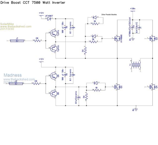 There are only 10 types of people in the world: those who understand binary, and those who don't. |
||||
| plover Guru Joined: 18/04/2013 Location: AustraliaPosts: 302 |
Thank you those two circuits will give me much fun. I can learn principles and gain experience with my ECAD program at the same time. This will give the good aim to do something specific while plowing through the program. The program already giving my memory a real work out. I will come back and start a new thread where I can ask questions and get advice and also show how I perceive the schematic. This will keep your thread free of interference.  |
||||
| yahoo2 Guru Joined: 05/04/2011 Location: AustraliaPosts: 1166 |
I found the hardest part of DEX is building a component library for the project, the schematic wiring was quite fast. I would give you my Oztules board.project file but it had gone AWOL in one of my hard disc swapping frenzies. I'm confused, no wait... maybe I'm not... |
||||
| Tinker Guru Joined: 07/11/2007 Location: AustraliaPosts: 1904 |
OK, these parts have arrived, what shall I do with them?   So far I have this: 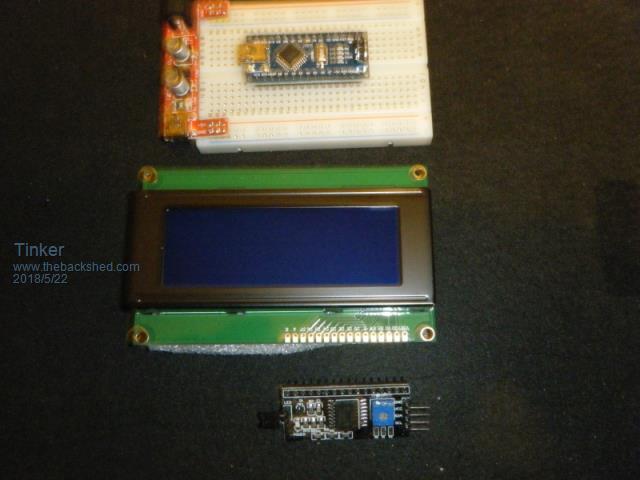 The nano, a display and a breadboard. Question about that display, it comes with a serial interface card which solders? to the board. Or is it better to use a socket? The pins are long enough for a socket. Also, there are no pin marks on the interface so it could fit on either side of the display. The website shows a pic with the interface fitted to the back of the display. Is this correct? I have no experience with this type nano so any suggestion where to read up on it are welcome. I did watch that flashing LED youtube BTW. And where is that "library", as often mentioned here, to be found? Presumably it has demo programs available there? I suppose I need to download some program that lets my laptop communicate with this Arduino. As there seem to be quite a few versions of arduino's, what exactly do I look for to download. Should I ask these questions over at the other forum? Thanks in advance. Klaus |
||||
Madness Guru Joined: 08/10/2011 Location: AustraliaPosts: 2498 |
This should keep you occupied for a few days Klaus. Just solder the display serial interface to the back of the LCD, you could put a socket if you think you might wire it up arse about face and kill the IC2 board. Goes like this 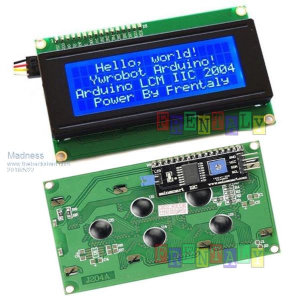 Start here with step by step instructions to setup your computer. Here is a very good video that goes through installing the LCD step by step. Just change the (16,2) to (20,4) don't worry that the video shows an Uno, it is essentially the same as a Nano but with a different PCB. Here is the Sketch I have just completed for the control board, it now includes low voltage shutdown as well as the fan control. This is the part of the Sketch with these settings. double HSsetpoint = 35; //Heatsink Target Temperature double TRsetpoint = 45; //Toroid Target Temperature int MinVolts = 47; //Battery Volts to shut down int TimeAtMinVolts = 20; //How many seconds below MinVolts till shout down is triggered int RestartTime = 10; // How many minutes to restart if battery volts recover above MinVolts I think that is explained well enough. Fan temperature settings uses a PID Algorithm, so it will run the fans as fast or slow as required to maintain the Temperature Setpoints. If you have installed a beeper it will continue to beep as long as the Inverter is shut down in low voltage condition. Pressing reset will avoid it beeping until the restart elapses if the voltage is correct. The display shows current temperature and next to that after the M: is the maximum temperature since the last reset. Next line shows fan speed as a percentage. Also you may need to fiddle with the resistor ratios in the code to get a correct voltage reading if there is insufficient adjustment. float R1 = 105000.0; // resistance of R1 (100K) float R2 = 8000.0; // resistance of R2 (8K2) For setting up voltage divider to get correct voltage reading Use in conjunction with trim pot on pcb I am also going to make a small modification to the PCB so you don't need to modify the addresses for each individual temperature sensor. You will need to download and install all seven of the libraries as shown after "#include" such as #include <LiquidCrystal_I2C.h [code] /* YourDuino.com Example: Multiple DS18B20 Temperature Sensors Displayed on 4x20 character LCD display DS18B20 Pinout (Left to Right, pins down, flat side toward you) - Left = Ground - Center = Signal (Pin 9): (with 3.3K to 4.7K resistor to +5 or 3.3 ) - Right = +5 or +3.3 V terry@yourduino.com */ /*-----( Import needed libraries )-----*/ #include <OneWire.h>// Get 1-wire Library here: http://www.pjrc.com/teensy/td_libs_OneWire.html #include <DallasTemperature.h>//Get DallasTemperature Library here: http://milesburton.com/Main_Page?title=Dallas_Temperature_Control_Library #include <Wire.h>// Wire (I2C) Library #include <PID_v1.h> //PID LIB for fan speed #include <LiquidCrystal.h>// LCD Library #include <LiquidCrystal_I2C.h> #include <avr/wdt.h>//Watchdog Lib // set the LCD address to 0x27 for a 20 chars 4 line display // Set the pins on the I2C chip used for LCD connections: // addr, en,rw,rs,d4,d5,d6,d7,bl,blpol #define ONE_WIRE_BUS 4 // Data wire is plugged into port 4 on the Arduino #define pwmH 6 #define pwmTR 5 /*-----( Declare objects )-----*/ // Setup a oneWire instance to communicate with any OneWire devices // (not just Maxim/Dallas temperature ICs) OneWire oneWire(ONE_WIRE_BUS); // Pass address of our oneWire instance to Dallas Temperature. DallasTemperature sensors(&oneWire); //-----------------------------CHANGE THESE AS REQUIRED--------------------------------------------------------------------------------- // Start the LCD display library LiquidCrystal_I2C lcd(0x3F, 2, 1, 0, 4, 5, 6, 7, 3, POSITIVE); // Set the LCD I2C address change this 0x3F or 0x27 if nothing on the LCD double HSsetpoint = 35; //Heatsink Target Temperature double TRsetpoint = 45; //Toroid Target Temperature int MinVolts = 47; //Battery Volts to shut down int TimeAtMinVolts = 2; //How many seconds below MinVolts till shout down is triggered int RestartTime = 1; // How many minutes to restart if battery volts recover above MinVolts //DeviceAddress Probe01 = { 0x28, 0xEE, 0x92, 0xD4, 0x2C, 0x16, 0x02, 0xCA }; // Address printed on Sensor connected to Heatsink //DeviceAddress Probe02 = { 0x28, 0xEE, 0xC1, 0x08, 0x1A, 0x16, 0x02, 0x0D }; // Address printed on Sensor connected to Toroid DeviceAddress Probe01 = { 0x28, 0xEE, 0x15, 0x12, 0x1A, 0x16, 0x02, 0x6F }; // Address printed on Sensor connected to Heatsink DeviceAddress Probe02 = { 0x28, 0xEE, 0x46, 0x1A, 0x2E, 0x16, 0x01, 0x0A }; // Address printed on Sensor connected to Toroid //------------------------------STOP HERE IF YOU ARE NOT SURE--------------------------------------------------------------------------- int HSmax; int TRmax; int FANtempH; int FANtempT; double tempTR; int tempTR1; double tempHS; int tempHS1; double fanspeedH; double fanspeedT; double fanpwmH; double fanpwmT; int fanpercentH; int fanpercentT; const int numReadings = 10; double Setpoint, Input, Output; int readings; // the readings from the analog input int readIndex = 0; // the index of the current reading int total = 0; // the running total int average = 0; // the average int voltsinputPin = A7; boolean singlecase = false; // true for all in one case, false for divided case with seperate fans for heatsink and toriod. float R1 = 105000.0; // resistance of R1 (100K) float R2 = 8000.0; // resistance of R2 (8K2) For setting up voltage divider to get correct voltage reading Use in conjunction with trim pot on pcb double vin = 0.0; double vout = 0.0; int beeper = 11;// the number of the beeper pin int beeperstate = LOW; int ShutDown = 3;// the number of the shutdown pin boolean beeping = false; unsigned long previousMillis = 0; const long interval = 750; // interval at which to beep (milliseconds) long LVStart; long timenow; long vingood; double Kp = 45, Ki = 20, Kd = 3; //variables for setting PID for fan speed control PID HSPID(&tempHS, &fanpwmH, &HSsetpoint, Kp, Ki, Kd, REVERSE); PID TRPID(&tempTR, &fanpwmT, &TRsetpoint, Kp, Ki, Kd, REVERSE); void setup() /****** SETUP: RUNS ONCE ******/ { Serial.begin(9600); wdt_enable(WDTO_1S); // Setup watchdog to reset after 1 second if no activity //------- Initialize the Temperature measurement library-------------- sensors.begin(); // set the resolution to 10 bit (Can be 9 to 12 bits .. lower is faster) sensors.setResolution(Probe01, 10); sensors.setResolution(Probe02, 10); //---------------- Initialize the lcd ------------------ lcd.begin(20, 4); // initialize the lcd for 20 chars 4 lines, turn on backlight lcd.setCursor(0, 0); HSPID.SetMode(AUTOMATIC); TRPID.SetMode(AUTOMATIC); pinMode(beeper, OUTPUT); // pinMode(ShutDown, OUTPUT); // initialize all the readings to 0: for (int thisReading = 0; thisReading < numReadings; thisReading++) { readings = 0; } }//--(end setup )--- void loop() /****** LOOP: RUNS CONSTANTLY ******/ { wdt_reset(); // Reset watchdog timer lcd.home(); lcd.backlight(); //Backlight ON if under program control lcd.setCursor(0, 3); lcd.print("V :"); lcd.print(vin); sensors.requestTemperatures(); // Send the command to get temperatures lcd.setCursor(0, 2); lcd.print(" "); timenow = millis(); lcd.setCursor(0, 0); //Start at character 0 on line 0 lcd.print("H:"); { tempHS = sensors.getTempC(Probe01); if (tempHS == -127.00) // Measurement failed or no device found { lcd.print("Error"); tempHS = tempHS1; } else { lcd.print(tempHS, 0); tempHS1 = tempHS; HSmax = max (HSmax, tempHS); lcd.print(" M:"); lcd.print(HSmax); } HSPID.Compute(); { tempTR = sensors.getTempC(Probe02); if (tempTR == -127.00) // Measurement failed or no device found { lcd.print("Error"); tempTR = tempTR1; } else { lcd.print(" T:"); lcd.print(tempTR, 0); tempTR1 = tempTR; TRmax = max (TRmax, tempTR); lcd.print(" M:"); lcd.print(TRmax); } } TRPID.Compute(); } analogWrite (pwmTR, fanpwmT); analogWrite (pwmH, fanpwmH); lcd.setCursor(0, 1); lcd.print("HSFAN% "); lcd.setCursor(6, 1); lcd.print(fanpwmH / 2.55, 0); lcd.setCursor(9, 1); lcd.print(" TRFAN% "); lcd.setCursor(16, 1); lcd.print(fanpwmT / 2.55, 0); { // subtract the last reading: total = total - readings; // read from the sensor: readings = analogRead(voltsinputPin); // add the reading to the total: total = total + readings; // advance to the next position in the array: readIndex = readIndex + 1; // if we're at the end of the array... if (readIndex >= numReadings) { // ...wrap around to the beginning: readIndex = 0; } // calculate the average: average = total / numReadings; vout = (average) / 20.0; vin = (vout) / (R2 / (R1 + R2)); // Voltage divider calculation if ((vin >= MinVolts) && (vingood == 0)) { vingood = millis(); } if ((vingood > 0) && ((timenow - vingood) > (RestartTime * 60000))) { vingood = 0; } if ((vin >= MinVolts) && (vingood == 0)) { lcd.setCursor(9, 3); lcd.print("VOLTS GOOD"); digitalWrite (ShutDown, LOW); beeping = false; } if (vin >= MinVolts) { LVStart = 0; } else if (LVStart == 0) { LVStart = millis(); } if ((LVStart > 0) && (timenow - LVStart >= (TimeAtMinVolts * 1000))) { lcd.setCursor(9, 3); lcd.print("LOW VOLTS "); digitalWrite (ShutDown, HIGH); beeping = true; } if (beeping == true) { unsigned long currentMillis = millis(); if (currentMillis - previousMillis >= interval) { // save the last time you blinked the LED previousMillis = currentMillis; // if the LED is off turn it on and vice-versa: if (beeperstate == LOW) { beeperstate = HIGH; } else { beeperstate = LOW; } } } } if (beeping == false) { beeperstate = LOW; } // set the LED with the ledState of the variable: digitalWrite(beeper, beeperstate); } //--(end main loop )--- [/code] There are only 10 types of people in the world: those who understand binary, and those who don't. |
||||
| noneyabussiness Guru Joined: 31/07/2017 Location: AustraliaPosts: 513 |
Ahhh i love arduino, once you get your head around it, soooo powerful... all those analog circuits you used to rig up for each job can all be done by that tiny little chip... I think it works !! |
||||
renewableMark Guru Joined: 09/12/2017 Location: AustraliaPosts: 1678 |
Nice work Mad, that looks like a lot of work. The only thing that hasn't come yet is the LCD. Is it possible to run the LCD cable a few metres so it could be read in the house? How long could you go? It would need prob 6m in this case. Cheers Caveman Mark Off grid eastern Melb |
||||
Madness Guru Joined: 08/10/2011 Location: AustraliaPosts: 2498 |
I have tried to upload all the libraries here but the new lcd one is too big, If you go here, click on the green download button and select the zip file. Klaus once you have installed the Libraries there will be example sketches under the examples in the file menu. I agree with Poida, you can do the Analogue stuff so easily and you have digital as well. Mark I am not sure about the length of the cable for the LCD you will have to Google it. There is the beeper there to let you know if something is wrong with the voltage, the power will go off anyway. I have not done it yet but I will also be adding a shut down for over temperature also. I tried making some ribbon cables for the control board to power board myself but something is wrong, some wires just don't connect so I have gone back to the ready made ones and just removed the top clip to give me the extra 100mm I needed. 2018-05-23_065819_Arduino-Temperature-Control-Library-master.zip 2018-05-23_064924_Arduino-PID-Library-master.zip 2018-05-23_065959_OneWire-master.zip 2018-05-23_070431_Arduino-Watchdog-Handler-master.zip There are only 10 types of people in the world: those who understand binary, and those who don't. |
||||
renewableMark Guru Joined: 09/12/2017 Location: AustraliaPosts: 1678 |
OK longer runs need a pull up resistor for sca and scl lines, need to work out a value now. Cheers Caveman Mark Off grid eastern Melb |
||||
oztules Guru Joined: 26/07/2007 Location: AustraliaPosts: 1686 |
"You will need to download and install all seven of the libraries as shown after "#include" such as #include <LiquidCrystal_I2C.h" Start rant..... Not going to happen for me. Requiring a reprogram just to change a component is not my idea of sensible for remote installation purposes. I can understand it in your circumstance... but for the real world it is stupid. A different program for every sensor out in the field.  for me thats at least 20 programs with 40 different 8 byte address's for me thats at least 20 programs with 40 different 8 byte address'sNo I will write a new program for universal probes, with no extra libraries so any neophyte can program the thing.... probably parallel communication for the data display too.... so no library changes required... and sensors that you can buy for $4 per hundred.. Sorry mad, I just think this is a backward step.... well executed, but wrong direction for my money. I will probably be in the minority on this one, but thats my feelings on it. Strobing the address's on a single line is cool as... but too high tech for no good reason or even a slight gain in anything. So thats only my opinion, and the reasons behind it end rant. On the cable connector... beware there are several different sizes of ribbon...... and this affects the wire to wire distances for the 10 lines. .......oztules Village idiot...or... just another hack out of his depth |
||||
Madness Guru Joined: 08/10/2011 Location: AustraliaPosts: 2498 |
In the previous posting I made I said I would be rewriting it so there will be no program change required to go from one inverter to another. If loading a few libraries is beyond someone's capabilities I don't really care. I was not designing it for a "Neophyte", however, with the changes I am planning you could load the sketch into a nano and plug it into any of these control board in any inverter with any sensors it will work. Also I was planning to post the raw code that could be loaded into an Auduino in few simple steps. If anyone is planning to use Arduino and never download a library they are severely limiting themselves and making a lot more work. A library is really just a bunch code bundled together to do a specific job. As for problems with wires to the inverter on off switch I had that happen today with wires about 120mm long, I replaced them with shielded wire and it is all good now. I guess I better not post what I am doing in my fantasy world with the GTI Charge controllers then so I don't get shot down in flames for that. There are only 10 types of people in the world: those who understand binary, and those who don't. |
||||
| Mulver Senior Member Joined: 27/02/2017 Location: AustraliaPosts: 160 |
Everyoneís opinions and ideas are what keeps this place innovative! Donít stop Madness I want to see your fantasy world!! Ozís opinions ( location, applications, users ) may have merit in his situation but do not apply to everyone! |
||||
renewableMark Guru Joined: 09/12/2017 Location: AustraliaPosts: 1678 |
Reminds me of a time a bolt didn't quite fit through a gap past a bit of aluminium. I was going to file it, by the time I found my file and came back my mate had got a chisel and hammer and gouged a dirty big slot. "works doesn't is" he proudly said. And yes he was right. My way would have looked neater though. More than one way to skin a cat. Cheers Caveman Mark Off grid eastern Melb |
||||
oztules Guru Joined: 26/07/2007 Location: AustraliaPosts: 1686 |
"In the previous posting I made I said I would be rewriting it so there will be no program change required to go from one inverter to another." I wonder how you propose to do that with the dallas temp sensors you have written this program for. As I understand it, the sequence runs like this.. 1. issue a reset command on the bus by pulling it low for minimum of 480millionths of a second, then going high via 5k pull up. 2.Once the bus master has released, the slave waits for 15-60us then responds by pulling the bus low for 60 to 240us... this is received by the master, as a presence signal. 3. Master transmits a 55hex match command 4. Master transmits 64bit hex address it has derived from your program. 5.Master issues convert T command ( converts temp data and stores in 2 byte data register..... master keeps bus high to provide parasitic power for the duration. 6.Master sends reset pulse, and then receives presence timing. hold low for 60-240us 7. Master reissues 55hex match rom command followed by the 64bit rom address again to get the right sensor to reply. 8.Now master sends read scratchpad command of BE hex 9. Master receives 9 data bits which includes the CRC code to check for integrity. Back to sleep now How can you address the slaves in sequence if you don't provide the address to the master to do the interrogation of the slaves. It has to have an address for this to work... doesn't it?..... and thats defined in the program. By definition, all programs will be different. If not, how/why not. It uses the 64bit address twice per interrogation. Or are you going back to dumb sensors..... like thermisters.... As Einstein is said to have commented, Everything should be made as simple as possible, but not simpler. So E=MC^2 looks simple enough...but looking behind it, the tensor maths is truly terrifying, and proves that there is no force of gravity between two objects... Newton was wrong... so simple is also not always as simple as it seems.... but I still like simple. Mark, the library provides the protocols for all this to happen, or you can program it in yourself. Not sure your analogy holds up here. Remember, while we are doing the millionths of a second timing pulses... we were/are unable to hold the data lines for the on-off switch successfully...for on anyway.. never mind the 15-60us stuff.. think about it. Even mad had to screen the leads over a 110mm length.... so what could possibly go wrong here?... and how would you find it if it did? I don't know the noise immunity of this sexy scheme, and I won't be finding out any time soon. Mad, just because I won't appreciate your GTI scheme because of complexities it does not need for perfect function, does not mean your wrong or I am right. I just have different needs to the suburban warriors here. ........oztules Village idiot...or... just another hack out of his depth |
||||
Madness Guru Joined: 08/10/2011 Location: AustraliaPosts: 2498 |
I used Digital sensors to avoid issues such as those that have turned up with the on off switch and the effects of magnetic fields inducing currents. Something I had been aware of could cause problems long before your discovery in the last week. The code I posted more than a year ago used the same sensors and there was no ranting about it then. As for addressing DS1820 sensors individually if each is on a seperate bus there is no need for an address. The board is made so those that want to add the Arduino can, those that don't want to can just leave it off. I never recieved the email detailing the requirements of the people of Flinders Island! Maybe when you wake up you will get out of bed on the other side of the bed and be in a better mood. *ReadDS18B20two vers: 6Jly14- Modified by Brian (twice!) for 5 sensors, better responsiveness. Derived from vers 18 July 2010 Started end of term eve WG/TA/LE/EW/JGB Reading five DS18B20s (Changed to 5 from the 2 allowed by the 18 July 2010 version of ReadDS18B20two) See... http://sheepdogguides.com/arduino/ar3ne1tt2.htm ... for explanation of this code. Code adapted from code from nuelectronics.com demo Revise the next five lines, as necessary, for where you have your sensors connected. Remove pre-pended "//"s. */ //#define tture1 33//no ; here //#define tture2 35//no ; here //#define tture3 37//no ; here //#define tture4 39//no ; here //#define tture5 41//no ; here int tture[5] = {33,35,37,39,41}; int x = 0; int count = 0; /*Forward declarations. Only the last two need concern the user Remmed out, as they seem unnecessary void OneWireReset(int Pin);//Called by readTture void OneWireOutByte(int Pin, byte d);//Called by readTture byte OneWireInByte(int Pin);//Called by readTture void readTture(byte Pin);//Of use to users void printTture();//Of use to users */ //Following globals used to communicate results back //from readTture(Pin), and to send data to printTture... int HighByte[5], LowByte[5], TReading[5], SignBit[5], Tc_100[5], Whole[5],Fract[5]; unsigned long pause1; void setup() { //For each tture sensor: Do a pinMode and a digitalWrite for (x = 0; x < 5; x++) { pinMode(tture[x], INPUT); digitalWrite(tture[x], LOW);//Disable internal pull-up. } pinMode(13,OUTPUT); Serial.begin(9600); delay(300);//Wait for newly restarted system to stabilize Serial.print("Temperature measurement, Five sensors:\n\n"); } /* The loop takes approximately 60uS The reading and printing take about 5.9mS One sensor is updated every 200mS All 5 are updated once per second. */ void loop(){ digitalWrite(13,!digitalRead(13)); pause1 = millis() % 200;// pause1 will loop from 0 to 199 if(pause1 == 0){ readTture(tture[count]);//N.B.: Values passed back in globals } if(pause1 == 150){ printTture();//N.B.: Takes values from globals. Also... Serial.print(" "); if(count == 0){ Serial.print("\n");//Start new line } } } //Everything below here... just copy it into your program "as is". //You are only likely to need to use readTture(pin) and printTture() // directly. Others are subordinate to those. //These routine access the following global variables... // int HighByte, LowByte, TReading, SignBit, Tc_100, Whole, Fract; void OneWireReset(int Pin) // reset. Should improve to act as a presence pulse { digitalWrite(Pin, LOW); pinMode(Pin, OUTPUT); // bring low for 500 us delayMicroseconds(500); pinMode(Pin, INPUT); delayMicroseconds(500); } void OneWireOutByte(int Pin, byte d) // output byte d (least sig bit first). { byte n; for(n=8; n!=0; n--) { if ((d & 0x01) == 1) // test least sig bit { digitalWrite(Pin, LOW); pinMode(Pin, OUTPUT); delayMicroseconds(5); pinMode(Pin, INPUT); delayMicroseconds(60); } else { digitalWrite(Pin, LOW); pinMode(Pin, OUTPUT); delayMicroseconds(60); pinMode(Pin, INPUT); } d=d>>1; // now the next bit is in // the least sig bit position. } }//end OneWireOutByte byte OneWireInByte(int Pin) // read byte, least sig byte first { byte d, n, b; d=0;//This critical line added 04 Oct 16 //I hate to think how many derivatives of //this code exist elsewhere on my web pages //which have NOT HAD this. You may "get away" //with not setting d to zero here... but it //is A Very Bad Idea to trust to "hidden" //initializations! //The matter was brought to my attention by //a kind reader who was THINKING OF YOU!!! //If YOU spot an error, please write in, bring //it to my attention, to save the next person //grief. for (n=0; n<8; n++) { digitalWrite(Pin, LOW); pinMode(Pin, OUTPUT); delayMicroseconds(5); pinMode(Pin, INPUT); delayMicroseconds(5); b = digitalRead(Pin); delayMicroseconds(50); d = (d >> 1) | (b<<7); // shift d to right and //insert b in most sig bit position } return(d); } void readTture(byte Pin){ //Pass WHICH pin you want to read in "Pin" //Returns values in... (See global declarations) OneWireReset(Pin); OneWireOutByte(Pin, 0xcc); OneWireOutByte(Pin, 0x44); // perform temperature conversion, // strong pullup for one sec OneWireReset(Pin); OneWireOutByte(Pin, 0xcc); OneWireOutByte(Pin, 0xbe); LowByte[count] = OneWireInByte(Pin); HighByte[count] = OneWireInByte(Pin); TReading[count] = (HighByte[count] << 8) + LowByte[count]; SignBit[count] = TReading[count] & 0x8000; // test most sig bit if (SignBit[count]) // negative { TReading[count] = (TReading[count] ^ 0xffff) + 1; // 2's comp } Tc_100[count] = (6 * TReading[count]) + TReading[count] / 4; //multiply by (100 * 0.0625) or 6.25 Whole[count] = Tc_100[count] / 100; // separate off the whole //number and fractional portions Fract[count] = Tc_100[count] % 100; } void printTture(){//Uses values from global variables. //See global declarations. //N.B.: No new line inside printTture if (SignBit[count]) // If it's negative { Serial.print("-"); } Serial.print(Whole[count]); Serial.print("."); if (Fract[count] < 10) { Serial.print("0"); } Serial.print(Fract[count]); count++; if(count == 5){ count = 0; } } There are only 10 types of people in the world: those who understand binary, and those who don't. |
||||
| gpalterpower Senior Member Joined: 19/07/2009 Location: AustraliaPosts: 175 |
Hi Madness, boards arrived today. They look good! Now for the assembly. Are you still planning on putting together a goodie bag together with all the parts? Thanks. Marcus. if it aint broke dont fix it!! |
||||
oztules Guru Joined: 26/07/2007 Location: AustraliaPosts: 1686 |
"As for addressing DS1820 sensors individually if each is on a seperate bus there is no need for an address." So, they are treated as just dumb sensors now.... may as well use thermisters again. Same wiring simpler program, same result. It's your thread Mad, you are of course welcome to do as you so choose. I still don't understand your choice at all.... but it is your choice. It makes no material difference which way you program it. I just don't like complex for complexity sake.... and now your going for non addressed ( dumb) digital, there is not even a pretense of an advantage anymore. It is the last I will say on the matter, I won't convince you to change, and you won't convince me to complicate a simple process, unless you can offer a useful reason, and I'm blowed if I can see one. Best wishes with it. .....oztules Village idiot...or... just another hack out of his depth |
||||
Madness Guru Joined: 08/10/2011 Location: AustraliaPosts: 2498 |
I got this Inverter running today, a single core from an Aerosharp with inner windings unmodified. PCB is a half size one with just 12 HY4008 MOSFETs in total. Ran it for one hour at 4KW and with the sketch posted this morning. It was around 25 degrees with the 2 heaters I had running and the toriod went to a maximum of 48 degrees and the heatsink 37. The PID algorithm does a very good job of controlling the temperature and it was only the long hard test that the fans got to 100% and the temperature rose to just above the setpoint. It worked perfectly with the plug in on/off switch but kept restarting with the switch on the front panel. That is when I changed to shielded wire and it has not missed a beat, the house has been running off it since late this morning. Now this one is running I am going to change the PCBs in my big inverter. 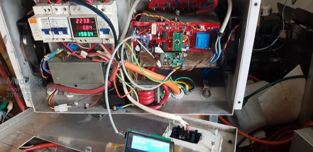 I got tied up on some phone calls will the 4KW test was running and did not get photos of that, but it would run 24/7 at that power level. 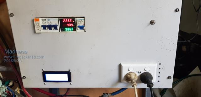 These 140mm fans help a lot. 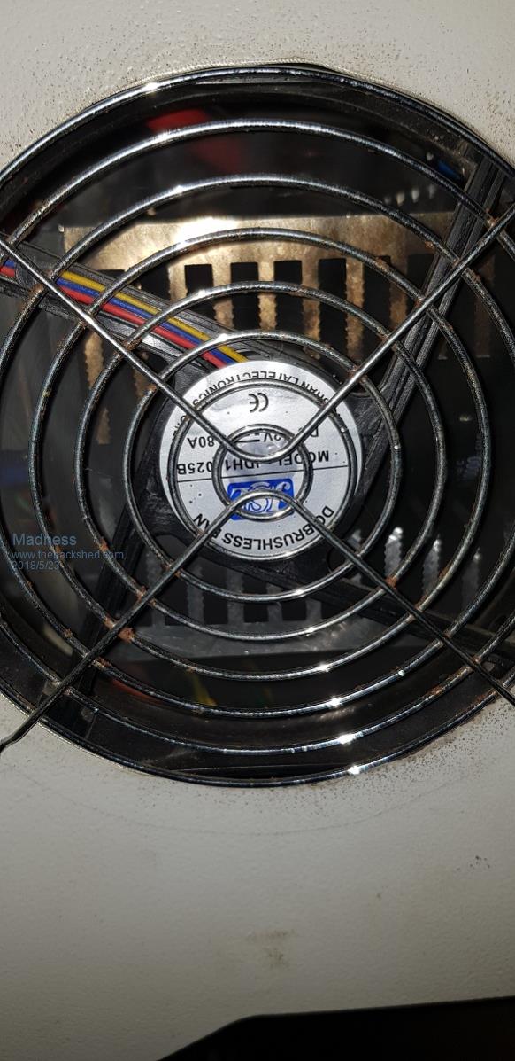 There are only 10 types of people in the world: those who understand binary, and those who don't. |
||||
| yahoo2 Guru Joined: 05/04/2011 Location: AustraliaPosts: 1166 |
PCB's arrived in the post Tuesday Thanks Madness. I will get to have a look at them tomorrow night. Cant wait I'm confused, no wait... maybe I'm not... |
||||