|

|
Forum Index : Electronics : Various aspects of home brew inverters
| Author | Message | ||||
| gigabyte091 Newbie Joined: 15/10/2018 Location: CroatiaPosts: 17 |
Yes, Im using EI type transformer, it came from an old UPS. Today i will finish another board with small 3VA transformer for feedback and put 5400 uF of capacitance on the input and see if power supply is happier with that. |
||||
| wiseguy Guru Joined: 21/06/2018 Location: AustraliaPosts: 1156 |
Poida, I am very impressed with the work you have done on the UNO PWM code for sinewave generation. I have not tried to run it yet but am keen to do so soon. A few weeks ago I contacted my ex software engineer to investigate & write some PWM code for a dedicated inverter function on a suitable micro controller platform (maybe ARM or similar) but having read more about your code and the successes others are having with it, maybe your software is quite suitable & the way to go. Am I correct that as yet the loop is not closed for sensing output voltage and maintaining a constant output level ? It seems that if you have a soft start function operating, there is already capability to control the output so is this the next logical step? Some requests I made of my software guru was to create a half sine wave and then repeat it exactly for the second half cycle to ensure there can be no walking flux occurring in the transformer. When stopping the inverter - unless it is an urgent shutdown - to stop at a 50Hz zero crossing to ensure the Toroidal flux is reset properly (your soft shutdown is probably fine for this too). The inverter output should always Soft start after any interruption. If I understand correctly you have a 50Hz output squarewave on 1 output pin and a HF PWM output on the other pin. These pins are connected to 2 half bridge drivers to created the 2 missing FET drives for full bridge switching? Lastly what are your further thoughts on creating the 4 signals for the FET bridge on 4 separate pins of the micro ? If there is a risk that the software could take its eye off the ball and kill things perhaps the 2 output pins approach and some external interlocked gating (or Warps opto drive scheme) is safer - how much faith should we place in the micro controller & 4 separate outputs approach ? Sorry for all the questions...... If at first you dont succeed, I suggest you avoid sky diving.... Cheers Mike |
||||
| wiseguy Guru Joined: 21/06/2018 Location: AustraliaPosts: 1156 |
I forgot to add what I had suggested to my software guru for a simple loop control. We discussed a successive approximation method where by we look at the output level compare it to our set point and then adjust the output gain accordingly to be halfway between where we are and where we should be. That way it should never overshoot and become unstable and would track changes relatively quickly and settle within a handful of cycles. Would this approach work & what are your thoughts on a method to regulate the output ? If at first you dont succeed, I suggest you avoid sky diving.... Cheers Mike |
||||
| gaspo Regular Member Joined: 25/06/2018 Location: AustraliaPosts: 65 |
Wiseguy, the Poida's code already has the output regulation via PID. One analog input is connected to trimpot for setting up the desired inverter output voltage. The second analog input is reading the feedback voltage from the transformer. The PID then calculates the difference and at each half cycle adjusts the PWM modulation to compensate. There are two versions of the code. One is generating output similar to EG8010 (50Hz square + 20Khz SPWM). The other is two sines shifted by 180°. Advantage of two pin output is that if combined with IR2184 (or IR21844) the MOSFET driver takes control of dead-time generation. The outputs of IR2184 are same as those in IR2110 and thus can be connected directly to existing power boards. |
||||
| wiseguy Guru Joined: 21/06/2018 Location: AustraliaPosts: 1156 |
Thanks for the clarification re feedback regulation Gaspo, great to hear. In my version/application, it has 4 separate power stages, each with optocoupler & TC4452 fast drivers (not discrete totem pole drive) hence my questions about 4 separate drive signals. Im trying to figure out if it would be safer/more reliable to generate the 4 signals I want using the micro or just to use the 2 signals it has & some discrete circuitry to get what I need - I'm thinking I might go the external discrete path. It feels like overkill to use the IR2184 just driving my opto couplers with some deadtime, but it might still be the simplest way. If at first you dont succeed, I suggest you avoid sky diving.... Cheers Mike |
||||
| gaspo Regular Member Joined: 25/06/2018 Location: AustraliaPosts: 65 |
Wiseguy, this particular chip (ATMEGA328P) used in some Arduino boards does not have the option to generate complementary PWM signal with dead time insertion. However, with some tweaking of Poida's code, I think it would be possible to generate EG8010 compatible signal via 4 pins. The 16-bit timer1 used for SPWM has two channels that can be configured such that it generates complementary outputs (SPWMOUT3/4). Then at each half cycle two additional pins can be toggled to produce complementary 50Hz signal (SWPMOUT1/2). All that would be without dead-time. If you are using opto-couplers connected in the similar manner as Warpspeed shown in number of his posts, using a capacitor on the opto -coupler inputs can produce dead-time. Warpspeed's clever connection of opto-couplers also prevents cross-conduction. |
||||
| Solar Mike Guru Joined: 08/02/2015 Location: New ZealandPosts: 1138 |
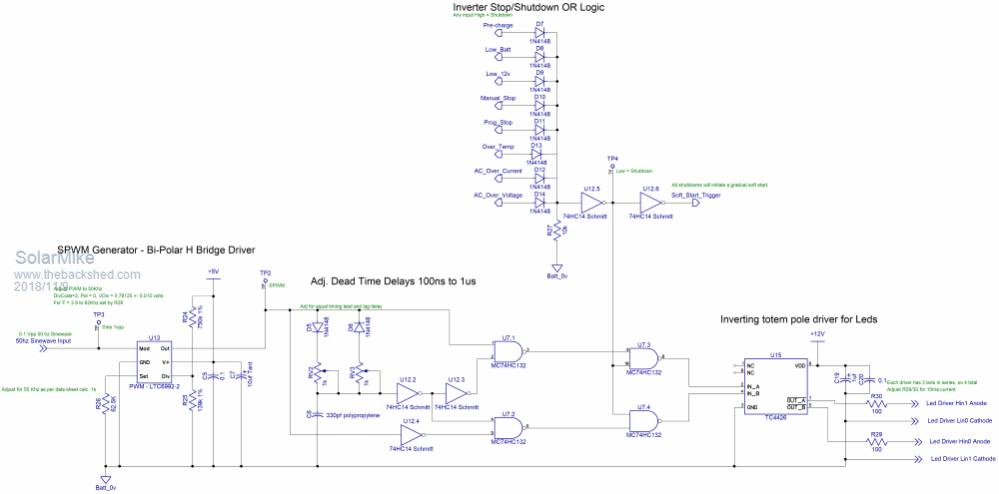
Hi Wiseguy, here is part of the circuit that I use to generate dead time, uses a few logic gates and gives you independent control of leading and trailing edge dead-time signal; thus you can set the correct dead-time at the gates of your final power stage taking into account any differing delays introduced by the high speed opto-couplers, drivers etc.  |
||||
| poida Guru Joined: 02/02/2017 Location: AustraliaPosts: 1418 |
Wiseguy: Gaspo already answered your question about control. In my experience, the PID control has worked flawlessly. As you might already be aware, low pass filtering of inputs of a PID can move poles into unstable phase angles. The Bessel LP filter, combined with the sample rate implied by A-D conversion within loop() (approx 4kHz) and the PID values asserted in the initialisation end up with a Stable Control Regime. I have tried to upset things with sudden load transients but it just works. I tuned the PID values carefully to suit the Arduino A-D sample rate of my code. My code when moving from standby to ON will ramp up to the AC output set point and when there will implement a "bang-bang" control until 2.5 seconds has passed. This 2.5 seconds is estimated to be close to the time needed to ramp up, in a linear fashion, to the set point. Once 2.5 seconds has passed, pwm control passes to PID. Sometimes there is an abrupt transition but usually things are close and the transition is smooth. Bang-bang control is no where nearly as good as PID control in maintaining output AC voltage. I could obtain a simliar result with immediate PID control effective after the standby to ON transition, with a ramping setpoint inserted into the PID control function. That is easy to code but I see no need to do this right now. You mention IR2184 as being overkill. I like the chips due to: 2 A outputs (both source and sink) $6 ea from RS Always got stock You might consider cheaper ICs such as IRS2004 at about $2.70 which do the same thing for your needs given you will provide higher current gate drive by other means. Solar Mike shows a way too, with discrete logic to give complimentary outputs from a single input. I am completely satisfied that the modest ATMega 328p is all you need to produce PWM signals and control an inverter. There is more than enough uC cycles to do the job. I have been looking at how much time is spent in the interrupt procedures (and so how much time is left for executing code in the main loop()..) and the fact is there is only 50% time used in interrupt code. This equates to approx 50% total cpu cycles left over to run the PID, look for over current condition, over/under voltage events, write data out I2C peripherals etc. This is plenty of time remaining after the main 20kHz interrupt code. I have not investigated how the ATMega 328p behaves with marginal and unplanned low voltage supplies, etc. I have looked at how it runs when correct supply is applied and it boots the boot loader then executes the stored program in flash. Completely determinable behavior. All you need to do is pull down the IR2184 shutdown inputs to ground on boot. A prior post of mine details why. By all means use my code or not, I do not mind. This is more of an exercise to show that we can make an inverter driver from scratch with a $10 uC, 2 x $6 gate drive ICs and $5 of discrete passives. And we know exactly what it will ever do and when it does it. wronger than a phone book full of wrong phone numbers |
||||
| poida Guru Joined: 02/02/2017 Location: AustraliaPosts: 1418 |
PID. In my codes, you might notice that it is in fact PD, I do not use the integral component of this control scheme. There was no practical need. Nearly all appliances and devices we have at home are happy to ingest something like 230V AC RMS. Lights might flicker a little when the AC voltage varies appreciably but I found the PID control as implemented in my code results in an output stable to +/- 1.5V AC. No flicker. Early posts in this thread explore transient load behavior of my inverter code running PID control. It's not bad... wronger than a phone book full of wrong phone numbers |
||||
| poida Guru Joined: 02/02/2017 Location: AustraliaPosts: 1418 |
Yes, one version emulates the 50Hz squarewave and SPWM sine, alternating polarity each half wave, a la EG8010. Other versions dispense with the 50Hx square wave. I found that this created significant issues, that could be mitigated to a satisfactory degree. I wanted to just put a sinewave into the transformer primary. And so the 2x sinewave code was born, and later, the 2x sinewave with variable AC output frequency version. These are much more smoother in the DC volts transitions. In fact there are no sudden DC transitions, just continuous PWM. (continuous PWM ?? I must be on drugs..) wronger than a phone book full of wrong phone numbers |
||||
| poida Guru Joined: 02/02/2017 Location: AustraliaPosts: 1418 |
I have code that outputs 4 signals, 2 pairs of low and high side drives for 2 half bridges. This runs on the Arduino Due (Arm Cortex M3 based uC) which provides PWM with adjustable dead time. I recall there are 4 channels, I only need to use 2 of them. The Due uC never missed a beat in my testing. I took the 3.3V logic outputs and fed them directly into the inputs of the IR2110 drive ICs of the EGS002 modules. Of course I isolated these inputs from the EG8010 IC that was still present on the module. It worked fine but I wanted to get away from using Chinese made modules. The Due uC provides very fine grained dead time control, via special control registers. here is a snippet of the code: I call this once, on initialisation.. void pwmc_setup() { //Configure PWM channels 0,1 (PWML0,PWMH0,PWML1,PWMH1), (port C.2,C.3,C.4,C.5), (pins P34,P35,P36,P37) REG_PIOC_PDR = 0x3FC; //B1111111100, PIO Disable Register REG_PIOC_ABSR = REG_PIOC_ABSR | 0x3FCu; //B1111111100, Peripheral AB Select Register pmc_enable_periph_clk(ID_PWM); REG_PWM_ENA = REG_PWM_SR | 0x000003; //PWM Enable Register | PWM Status Register (activate channels 0,1), was B11111 ie all 5 low REG_PWM_CMR0 = 0x10000; //Channe0 Mode Register: Dead Time Enable DTE=1, clock divider = 0, use Mclk REG_PWM_CMR1 = 0x10005; //Channe1 Mode Register: Dead Time Enable DTE=1, clock divider = 5, use Mclk/512 REG_PWM_DT0 = 0x2a002a; //Channe0 Dead Time Register REG_PWM_DT1 = 0x020002; //Channe1 Dead Time Register REG_PWM_CPRD0 = 4200; //Channe0 Period Register 20 kHz REG_PWM_CPRD1 = 52500; //Channe1 Period Register 50 Hz NVIC_DisableIRQ(PWM_IRQn); // set up interrupt NVIC_ClearPendingIRQ(PWM_IRQn); NVIC_SetPriority(PWM_IRQn, 0); NVIC_EnableIRQ((IRQn_Type)36); //NVIC_EnableIRQ(PWM_IRQn); PWM_INTERFACE->PWM_IER1 = 0x0003; //enable interrupt on channel 0 PWM_INTERFACE->PWM_IDR1 = 0x00FF00fc; //enable interrupt on channel 0 // enable 16 pins in port D REG_PIOD_PER = 0x00ff; REG_PIOD_OER = 0x00ff; REG_PIOD_OWER = 0xFFFF; } The two PWM timers can have the front and back end of the PWM dead time individually determined. REG_PWM_DT0 is set to 0x2a002a. This means the front and the back end dead time is set to 0x2a clocks. I can make them anything I want, within reason. Here is the complete code. 2018-11-09_195405_due_inverter_1.ino.zip This code will compile and run ONLY for an Arduino Due. But if anybody looks at it you might recognise a few common idioms I seemingly always employ. wronger than a phone book full of wrong phone numbers |
||||
| poida Guru Joined: 02/02/2017 Location: AustraliaPosts: 1418 |
Gaspo, I must say that you understand my code well. I could not have explained it better myself. wronger than a phone book full of wrong phone numbers |
||||
Revlac Guru Joined: 31/12/2016 Location: AustraliaPosts: 1022 |
Thanks Poida for all the work you have done on this, I have learnt a lot along the way. When I started looking at inverters for off grid there where many different inverter builds going on around the net, most of them were far to complex and expensive to build and my lack of any idea how they worked.  At the time I did see a few Arduino based inverters around, all built as examples but not one that I could see, was ever setup running a house, for whatever reason at the time. I also went to Jaycar and asked them about it, and was told I need this, that and something else, that was enough to empty my wallet several times.  There has been much improvement since then and less parts and expense in total. I look forward to building one of these.  Cheers Aaron Off The Grid |
||||
| gaspo Regular Member Joined: 25/06/2018 Location: AustraliaPosts: 65 |
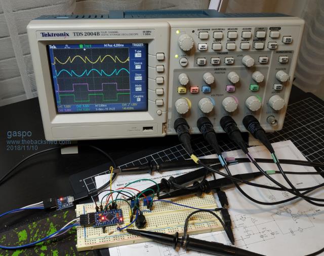
Here's Arduino 328P 4 lines mod simulating EG8010. 2018-11-10_002954_uno_inverter_eg8010.zip  |
||||
| poida Guru Joined: 02/02/2017 Location: AustraliaPosts: 1418 |
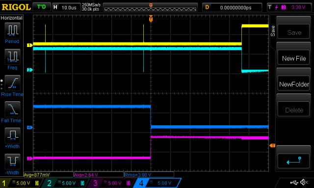
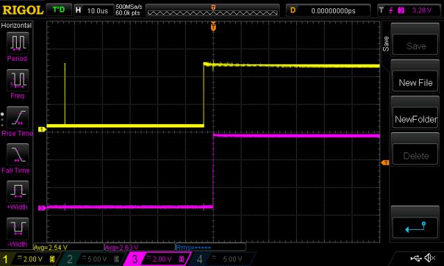
Gaspo: I can read my own code better now with some sensible variable names, moving a little bit of code here and there because it's more sane. Dead time will be provided by gate drive circuits of course. I wonder how your prototype will turn out, I can't wait to see. One thing I found with the 50Hz / 20kHz combination is that I could never obtain the exact timing of the 50Hz signal with respect to the SPWM as the sine wave passes through zero. Maybe 5us difference was the smallest I could achieve and that was with some very unclear ordering of events in the 20kHz interrupt block. The bigger the timing mismatch of this transition from high/low or low/high, the bigger the wobble in the output AC frequency. This transition in effect delivers a pulse to the primary, of the duration of the mismatch - exactly when we want to drive a zero voltage (it's the AC sine waveform zero crossing point isn't it?). I think your code might display a bit of a wobble in the AC which you just can't ever remove. Do not accept my view on this, please show me how to do it better. This timing mismatch was what keeps me using the 2x sine code. Here is the mismatch for your code:  Here is the mismatch for my code (which requires IR2184 or similar 1/2 bridge driver)  code used is 2018-11-10_124856_uno_inverter_Vfb_PID_Bessel_Vfb_smoothing.ino.zip It came down to the difficulty of changing the polarity of the SPWM at the exact time required. I found that I could move the 50Hz transition time around a bit, via unclear code placement, arriving at 5us best result. This still injects a 5us pulse of DC supply into the primary winding when we want zero volts.... wronger than a phone book full of wrong phone numbers |
||||
| poida Guru Joined: 02/02/2017 Location: AustraliaPosts: 1418 |
My aim in this is foster some threads where we explore details of home brew inverters. I wanted to bring some investigative rigor to the forum, in the belief that we would become more methodical in our work. If could be so bold I would like to suggest you start with a small inverter that just works, no matter what. And then build a bigger one maybe for household supply duties. The first one might be based on one of these inverter boards and modify the EGS002 to remove over current cut-off controls. There are two. Place 18 volt TVS devices on all 4 gate drive outputs. Feed it with a 32A DC contact breaker, maybe add inline 40A car fuse too. Get a 1500VA toroid from an Aerosharp, an E core ferrite for $15, a box and a bit of sundry stuff...no problems. The primary wire I use is 6mm2 dual core solar cable. I strip the outer covering and wind the primary with 2 in hand, 3 in hand for the inductor. You would end up with something that will start and run a fridge, all home IT stuff, TV, etc. for about $200 or so. All it has to do is run at about 500W, with occasional peaks. wronger than a phone book full of wrong phone numbers |
||||
| poida Guru Joined: 02/02/2017 Location: AustraliaPosts: 1418 |
I am developing an LCD display code that can fit inside the limited time slots of the inverter code. Naive I2C code using the Arduino supplied driver takes far too long. I ended up maintaining a copy of the 20 x 4 characters locally, updating them at the end of the PID loop which runs at 100Hz. This local copy of 80 characters is then fed into the LCD, one character each PID update. This means a screen refresh rate of about 1 Hz. It works! And it does not upset the PID loop control by adding delay into the feedback loop. Well, not too much anyway. First attempt shows inverter ON/OFF, PWM duty cycle, AC output set point (in ADC units) and AC output voltage (in ADC units). You can see how closely the PID loop can keep it to the set point. Video here: LCD Cheap parts, $10 for an I2C to LCD adaptor from Jaycar, you can get them for 1/3 on ebay, and the 20 x 4 LCD for about $15 or so. wronger than a phone book full of wrong phone numbers |
||||
| gaspo Regular Member Joined: 25/06/2018 Location: AustraliaPosts: 65 |
Poida, you are right - not ideal to synchronize 50Hz with 20Khz via code. This needs to be done by hardware. 328P cannot do it. It needs a timer with 2 channels each able to output complementary signals. I think higher end ATMEGAs can do it and probably all ARM Cortex devices. I will move onto STM32. After some code rearrangement I got it down to 3.5us |
||||
| poida Guru Joined: 02/02/2017 Location: AustraliaPosts: 1418 |
Gaspo, I've had a crack at it with the Arduino Due (Cortex M3) and when using PWM only (no bit fiddling from within the interrupt block) I could not get it close to the 5uS of the 328p code. Please share your STM32 code here so I can have a look at it. It likely will appear as Alien Runes to me but it might be a start point for some hacking. I like hacking. wronger than a phone book full of wrong phone numbers |
||||
renewableMark Guru Joined: 09/12/2017 Location: AustraliaPosts: 1678 |
Bit late for me as I have all the circuit boards done for inverter no 2 (and 2 spare sets) but do you plan on making control boards available? Cheers Caveman Mark Off grid eastern Melb |
||||