
|

|
Forum Index : Electronics : 8 KW Inverter Build
| Author | Message | ||||
Madness Guru Joined: 08/10/2011 Location: AustraliaPosts: 2498 |
So far I have not had any success with adding drivers, I have ordered some IRS2186S driver IC's. These are rated at 4 amps rather than the IR2110's 2.5A, they work exactly the same as the IR2110's but unfortunately have the pins moved around so they won't just drop into the existing boards. The ones I have ordered are surface mount and are a lot cheaper than the type that will plug into a socket. What I plan to do is put them on a small PCB similar to how we mount the EG8010 and fit them on to the power PCB. In the research I have done there is lots of mentions about keeping the distance between drives and the MOSFET's to minimum. Another thing I have found too is that the high side drive should be run as close as possible to their relevant ground (the Bridge). This is the same as how it has been done on the Chinese boards and Clockman's. I built another power board last week and it all worked perfectly with 24 MOSFETs giving a perfect waveform, then I added CAPS to the board and spikes appeared and the idle current went from 0.25A to 5A. Meanwhile I have been trying to isolate why I am getting different results to others and in Poida's thread there is mention of tank circuits etc and what could be causing ripples etc. My heat sinks are very large and electrically part of the primary circuit to the transformer. So I have made a half size test PCB and used some offcuts of heatsinks to make a minimal size version. So far this is woking perfectly. Idle current with the single core toroid is around 12 watts. The heatsink on the control board is from a flat screen TV, they have lots of nice squat heatsinks like this that don't add any unnecessary height to the PCB. 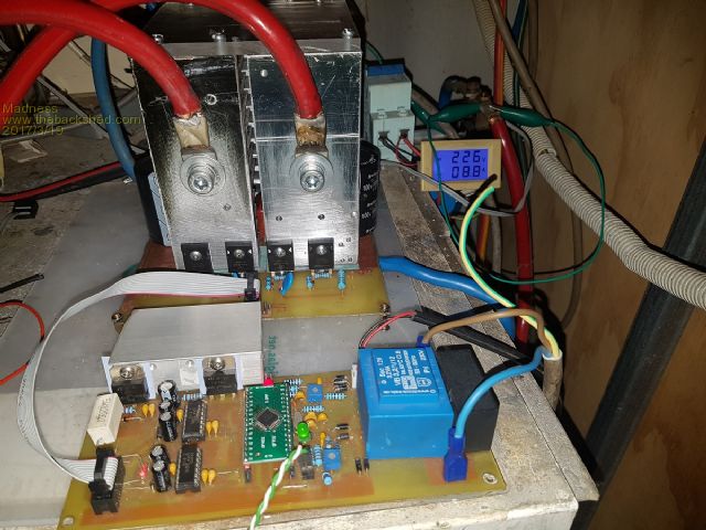 This is with no load 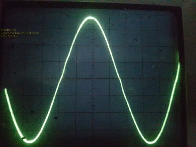 This is with load as shown in the first image 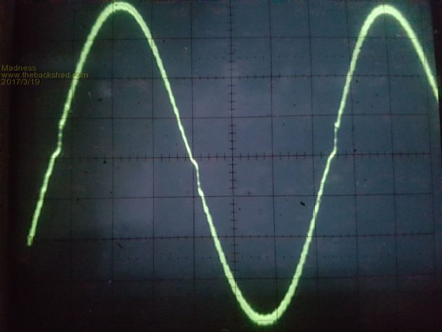 There are only 10 types of people in the world: those who understand binary, and those who don't. |
||||
Madness Guru Joined: 08/10/2011 Location: AustraliaPosts: 2498 |
Thanks to Solar Mikes help to post the gate drive circuit here I have the best results I have got so far. Life has got in the way the last week and finally today I got the PCB completed. 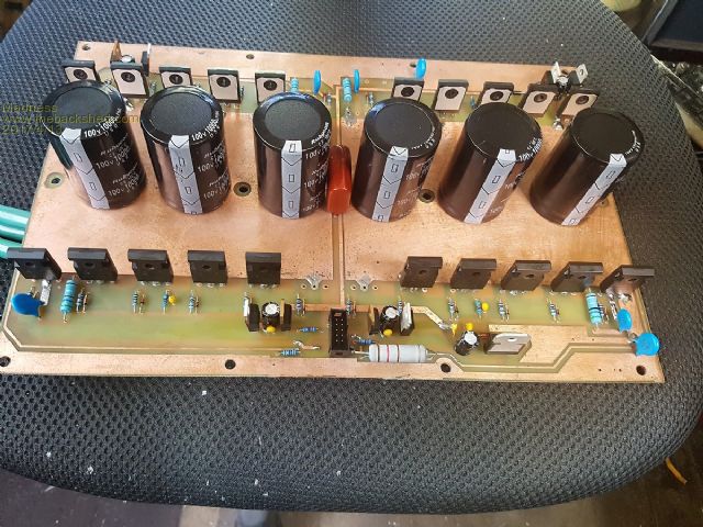 There is room for 4 extra MOSFETs but I don't think they are needed as the HY4008w's are rated at 200A. Idle power with the big Toroid is 40W, I have had it running at 5KW for about 10 minutes, I will give it a bigger load test tomorrow when the sun is out. Here it is running at 350W running the house. 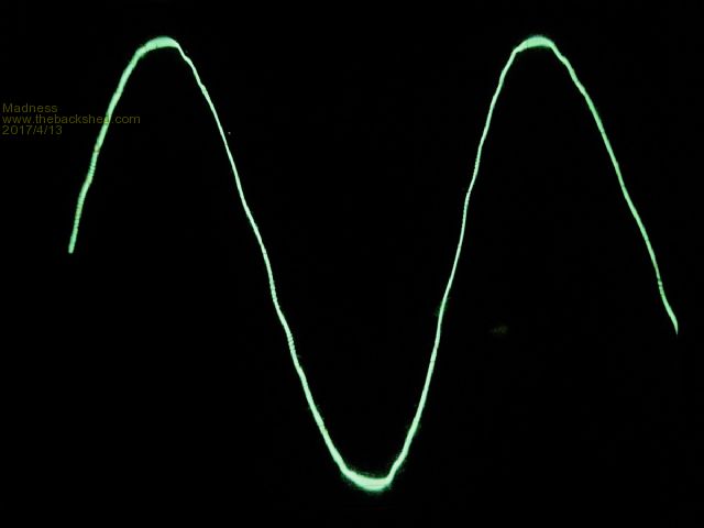 Not sure what was on when this was happening but it only did this with a particular load combination and normally it is much smoother as above. 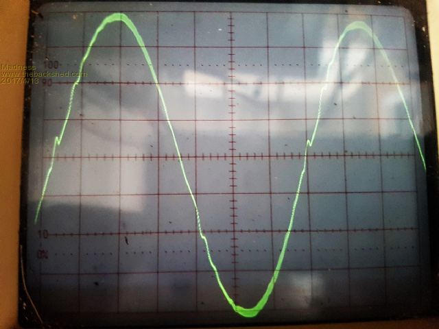 There are only 10 types of people in the world: those who understand binary, and those who don't. |
||||
| Tinker Guru Joined: 07/11/2007 Location: AustraliaPosts: 1904 |
Hi Gary, Not much is happening here but a while back I experimented with different chokes and had surprising results. Previously I found that more turns (up to a point) give a lower idling current. But this gives not the best sine wave output. Using that 120mm ferrite ring - which was much easier to wind turns on or take turns off - I found 4 turns gave the best results. Better trace than 4.5 turns on the common ferrite E core. Better trace than 3 turns on a slightly bigger ferrite E-core. It looks like the toroid & choke have to be 'tuned' for the best output wave form. You might want to experiment with this idea since you have a working power board. Mine is held up presently, too many other projects. My test rig had the TC4452 getting very hot, I think being driven by the IR2110's was too much input for them. I will try that totem pole drive next but power it from 4 x TC4452's instead of the IR2110's. Klaus |
||||
Madness Guru Joined: 08/10/2011 Location: AustraliaPosts: 2498 |
Hi Klaus, I agree the Choke has a big effect, I have gone back to the Ecore that you made for me ATM. The steel housing I made for it seemed to be getting warmer than the choke itself, perhaps it was acting as a short circuit turn. So I have removed the housing and have it strung up on some cable ties like a spider web, seems to run better. Idle current is around 40W with the double core Toroid so it is not that bad. With minimum dead time I have not had any luck with the ferrite ring I have. The TIP 41c/42c driver circuit seems to work well and does not run hot, I had too many hassles trying to get the TTC4452's working and gave up on them. They work well with no changes to the control board. I am still having issues with trying to get the Aero-sharp to back feed. I had it running today and working well with up 1300 watts going back into the Inverter for a while. But something goes wrong and it makes horrible noises, the wave turns to crap and it popped the 20A AC breaker. Could be the GTI too, I will have to try resurrecting another and see if it behaves any better. There are only 10 types of people in the world: those who understand binary, and those who don't. |
||||
oztules Guru Joined: 26/07/2007 Location: AustraliaPosts: 1686 |
i still just don't know why... walked out to the shed, turned on the scope, the unit was doing 4-5 kw, and the wave was perfectly shaped but for a slight zero cross over on one side of the wave only. I just cant see why yours is warped and mishapen.. danged if I can... it is annoying, as your board looks the full monty too  ... very nice.. ... very nice..I wish I knew why. Wave at 4-5kw ( see next pic for figures ) Curent status is: So this one has been under test for 140kwh Mad, this one is running 4 hy4008 on the outputs, still does the 20kw thing for the 5hp motor... so 6 is excessive for this size unit I think. The waveform barely differs from the 6x4110's, but easier to build and cheaper on the fets too  ............oztules Village idiot...or... just another hack out of his depth |
||||
Madness Guru Joined: 08/10/2011 Location: AustraliaPosts: 2498 |
Hi John, You have been quite lately. Some of us are more lucky or different DNA or something, I had somebody point out to me this thread you started on a different forum. On there you talk about the Power Jack you were playing with and how a GTI would not work with it when it had no choke. No matter what I do also the wave gets fatter at the peak when under load. I am planning to do more experiments with chokes, today I have been unwinding the toriod from a 1 KW SMA GTI. I was planning to build a 12V version for camping but it might be far better to buy a cheap 600W inverter for that. Anyway, I was wondering how the smaller toroid core would go as a choke, also it had a choke on both sides of the toroid. Later tonight I am planning to read Poida's thread again about Inductors. Can you post details again please of the choke you use? The board above runs very cool with the 5 FETs I have no plans to add anymore although I have another 80 sitting there. With the small PCB shown back a few posts above here, I am planning to build a single core inverter with it and use the heatsink of the little SMA GTI. If I cut it in half and cut one half in half again it will be just the right size, only other thing I need to do is make room for the caps. There are only 10 types of people in the world: those who understand binary, and those who don't. |
||||
| Solar Mike Guru Joined: 08/02/2015 Location: New ZealandPosts: 1138 |
Chokes.... I am about to start winding my choke and have a question that perhaps someone can enlighten with an answer. Why do we have a choke with a single winding on it, connected to either leg of the transformer?. We know that at the instant of switching the mosfets, the transformer primary wants to draw an enormous short duration spike, supplied by that big bank of C's until its magnetising field builds up, the choke reduces this for a short time until it gets saturated then acts like a short piece of wire. So what would happen if the choke was wound as per a common mode, with opposed windings, each connected to a leg of the transformer, the inductance is thus on both sides of the transformer and the current induced magnetic fields would cancel, so preventing saturation ? Thoughts.... Cheers Mike |
||||
oztules Guru Joined: 26/07/2007 Location: AustraliaPosts: 1686 |
"You have been quite lately."...... I would love to help you folks, but I have nothing to sensibly add to the discussion as you and tinker are doing things I have not needed to try. There are 5 of these things going about their business out in the wild, on far flung islands to normal environments, and only one had a shutdown,... why I don't know, but it was noisy and bothered me from the start... it got dismantled and reborn, and since then many MWH have been inverted by those five units every day. Because of the above, I have not had the need to change anything as yet, so I follow your foibles, in the hope we will all learn something that will explain your present doldrums...... I just can't understand it as you know. I am pretty sloppy with the inductors I must admit, and have no idea of whats in that particular inverter... will get pics of the ( I think torroids in this one) inductors tomorrow for you to peruse. That little zit in the scope was due to the chinese ( 700ltr ) freezer running. If that goes off leaving predominately resistive loads ( water bbq jug etc ), there are basically no blips at all. The washing machine does the same thing if it's heater is off...if on, then less pronounced for the 700w or so of motor starting and stopping all the time. Yes the experiments with the PJ boards and the GTI did blow o/loads without the choke... and I don't know why really... and I have not repeated the scenario as you would understand... it looked like the PJ was toast for a second or two... so I was not keen to do that again to double check. Once the choke was there, it works for years every day out on one of the islands in particular ( uses 2kw of solar a long way from the batteries, so now helps run the salt water RO from down where it is since it was installed this year. Also the generator back up consists of a few kw of cap excited genny, through caps, rectified, and then through aerosharp 3kw unit... once again, way down in the shearing shed, so it is not really heard from up at the house, but still charges the battery and runs the house when the batts are low...... so continue your tests. There is also one where the AWP mill is, and he has 2 x 1.5kw aero sharps running backwards every day for the last ... probably 3-4 years I guess. Mike.... I want saturation after a few nano seconds... but even so, the effective frequency will have dropped off anyway... ie it is only the freq of the high speed change in voltage over a change in time that we are trying to interact with.... the moment we get near switched on, we want minimum interference from the choke for max current transfer to the torroid. So we may be in the 100mhz range for x nano seconds, and drop off from that quickly... in fact the faster we switch, the shorter the time the inductor will do any useful impediment to the current flow.... If it saturated as well, that would be nice..less leakage... I don't think 20khz will be too involved with a few uH. The ferrite inductors don't seem to get very warm in operation, so their duty cycle must be brief.... powder iron cores seem to warm up much more. Or in other words, perhaps test your theory, and see what happens in practice, it is difficult to guess accurately in these circumstances... as we don't know for certain what is happening in there in any case. ..........oztules Village idiot...or... just another hack out of his depth |
||||
| Warpspeed Guru Joined: 09/08/2007 Location: AustraliaPosts: 4406 |
This is a complex issue, and there are several quite different problems and solutions. As we know, PWM involves an extremely violent switching from rail to rail at a relatively high switching frequency, and what we need to do is average out these fast transitions to recover some kind of long term averaged value that hopefully comes out looking like a 50 Hz sine wave. To do that we need a low pass filter with some energy storage capacity. This filtering must have very low power loss at 50Hz, and have suitably high attenuation at the PWM switching frequency. Another requirement is that the input impedance of our filter must be high enough that we do not produce very large current spikes when attempting to drive it. A third requirement is that the output voltage stays where we want it (240v) and have fairly good voltage regulation over a wide load range, which means a low output impedance at 50 Hz. All this is not an easy thing to achieve. The basic building block usually starts off with a transformer, often with a fairly large step up ratio. This transformer will have some particular characteristics depending on size, method of winding, and type of core material. As a result it will have some primary leakage inductance, and a self resonant frequency, mostly due to the unavoidable inductance and capacitance of the high voltage secondary that has a great many turns. Primary leakage inductance is what you can measure across the primary with the secondary shorted out. A perfect transformer with perfect primary to secondary coupling would look like a short at the primary, when the secondary is shorted. A real transformer will always have "some" primary leakage inductance. But the amount of leakage inductance is highly variable with turns ratio, physical size, method of construction and winding method. Self resonant frequency too will be highly variable, and if its above the PWM switching frequency, the transformer primary will look like an inductor at the PWM frequency. If the transformer self resonant frequency is below the PWM frequency, the primary will look like a capacitor, even with nothing connected across the secondary. So before we even start to look at designing out output filtering "system" we have some fairly significant unknowns about what the transformer primary is going to look like as far as being driven by the PWM power stage at the switching frequency. If its predominantly capacitive, there are going to be some current spikes. Even more so if there is a fairly large capacitor connected directly across the secondary winding, as there often is. Or maybe the primary leakage inductance is high enough for that not to matter ??? No way of knowing without measuring what you actually have, instead what you think you have. Now driving a highly capacitive load at high switching frequency is really bad news, we really need for our PWM output to go into something that looks more like a buck regulator, with a series inductance, where the current ramps up and down controllably. Maybe we need to add some extra inductance to the primary, or maybe not. How much is anyones guess unless you can look at the current in the primary and know what is really happening. The problem here is that too much inductance (or resistance) in the primary will create a power loss and degrade voltage regulation. If the necessary inductance is provided by the transformer leakage inductance, it will always be there, and will hardly change over the whole power range, because the transformer never magnetically saturates. The same may not be true of any externally added choke. Here it starts to get really complicated, because we can add a primary inductance that deliberately saturates at very low current for a specific purpose. This adds a fair bit of inductance to greatly reduce turn on switching loss for a very short time interval when the mosfets initially turn on. This can significantly reduce the no load inverter idling current, but its tricky, because how much inductance and how quickly it saturates and at what current it saturates has to be matched to the particular switching times and what the primary looks like. All of which is highly variable. What works in one inverter may not be optimum or work at all in another inverter, so its wide open to experimentation. But what you need is a fairly large ferrite core with high permeability, and an optimum number of turns found by experimentation. More turns are not always better. Its a case of sustaining sufficient inductance for sufficient time, and more turns will saturate sooner than less turns, but more turns would have higher initial inductance. So its cut and try, rinse, repeat... What you end up with probably will not work for someone else. This magic ferrite primary choke is just the icing on the cake. If your transformer has insufficient leakage inductance, your mosfets are going to have a very difficult time at high power, and a larger non saturating series inductance in the primary may be required. Just about all grid tie inverters that run at high voltage have such an iron cored monster, usually about 2mH to 3mH. But low voltage battery inverters usually do not, often the transformer itself is quite sufficient. Old inverters with E and I transformer laminations almost always have sufficient leakage inductance, but modern toriods have much more efficient primary to secondary coupling and that high efficiency and better coupling may be creating a problem. So in the end its difficult to know where you are, or what to do without having the equipment to look at voltage and current waveforms in the primary, and trying to make life for your mosfets as stress free as possible. Cheers, Tony. |
||||
oztules Guru Joined: 26/07/2007 Location: AustraliaPosts: 1686 |
Ok Mad, It is a torroid ( powdered iron I think ) with 6 or so turns.. pic tells it all.... Here is the set up. ........oztules Village idiot...or... just another hack out of his depth |
||||
Madness Guru Joined: 08/10/2011 Location: AustraliaPosts: 2498 |
Warp, thanks for the very detailed response, I will need to read it few times to get my head around it all. Oz, I see you don't make any special effort to wind the inductor tight or anything, maybe I am barking up the wrong tree with the inductor?????? Another thought I had after sleeping on it is to try Bipolar, I see that would involve some modification on the control board as well as per the circuit below. 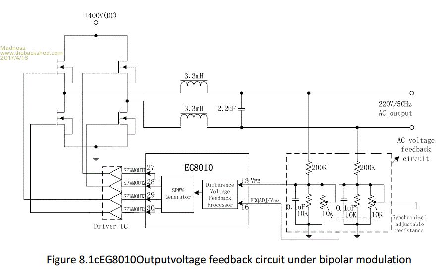 Also I am thinking if a common mode ferrite ring choke would work with it. There are only 10 types of people in the world: those who understand binary, and those who don't. |
||||
| Warpspeed Guru Joined: 09/08/2007 Location: AustraliaPosts: 4406 |
A toroid can be as ugly as sin and it will work fine. One pass through the hole equals one turn, no matter what the wire does to get back around to the other side around the outside of the toroid. One pass = one turn even if the wire around the outside as a foot long. No need at all to wrap it tightly. Here is a thought experiment for you. We generate a nice clean half sinusoid in high frequency PWM that starts off at zero, rises to a peak then falls back to zero. We can use a buck regulator circuit to limit the current and filter the PWM from the output. 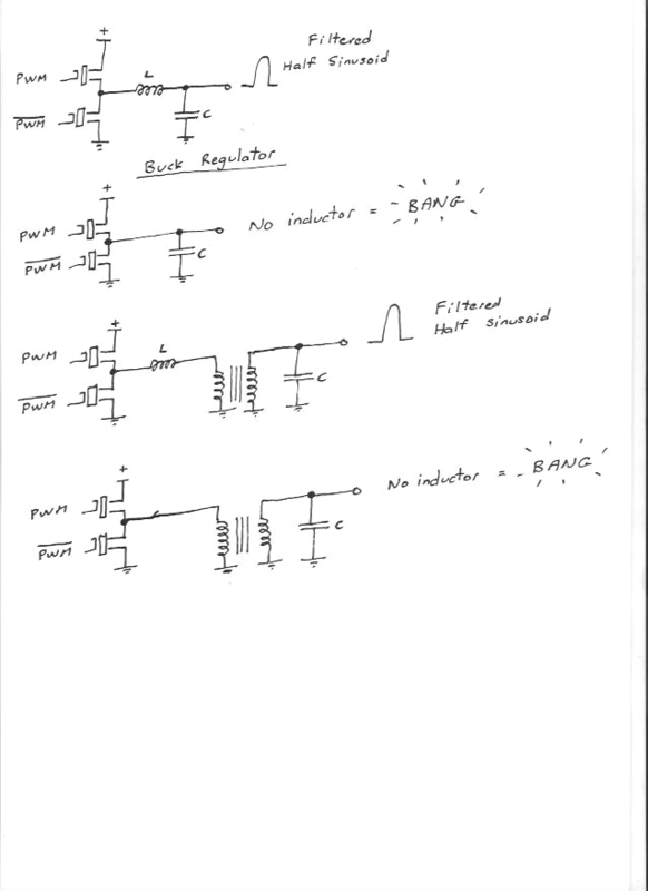 If we remove the inductor completely, we might be in trouble with a massive current inrush spike into the output filter capacitor. This will work fine provided the inductor L is of sufficient value and does not saturate. We could also modify the circuit by fitting a low frequency transformer after the inductor to step our half sinusoid up or down in voltage. That will work fine too, but the inductor "L" absolutely must be there. You will always find a physical choke fitted where the dc input voltage is high, as is common for grid tie inverters. If the incoming dc voltage is low (say 12v) there will almost always be sufficient leakage inductance in the transformer to perform the function of "L" unless the PWM switching frequency is very low. At mid voltages, (say 48v) an external physical choke may or may not be required, but you had better make sure, because leaving it out may cause you and your mosfets a lot of grief, particularly at high power. Leakage inductance can be measured directly by dead shorting the secondary and measuring across the primary with an inductance meter. There has to be enough !! Cheers, Tony. |
||||
| Tinker Guru Joined: 07/11/2007 Location: AustraliaPosts: 1904 |
OK, so I did just that today. Short circuit secondary (240V winding), the primary measures 0.6uH. Not short circuit, the primary measures 0.7uH. For comparison, the secondary with primary open measures 93.43 mH. (that's milli H) And the best choke I had for that measured 112uH. Do these figures make more sense to you than me?  Klaus |
||||
Madness Guru Joined: 08/10/2011 Location: AustraliaPosts: 2498 |
I finally made a proper heatsink for the mini Inverter shown here previously. It has 12 4110 FETs all standard Oztules circuit just minus 12 FETS and 2 caps. 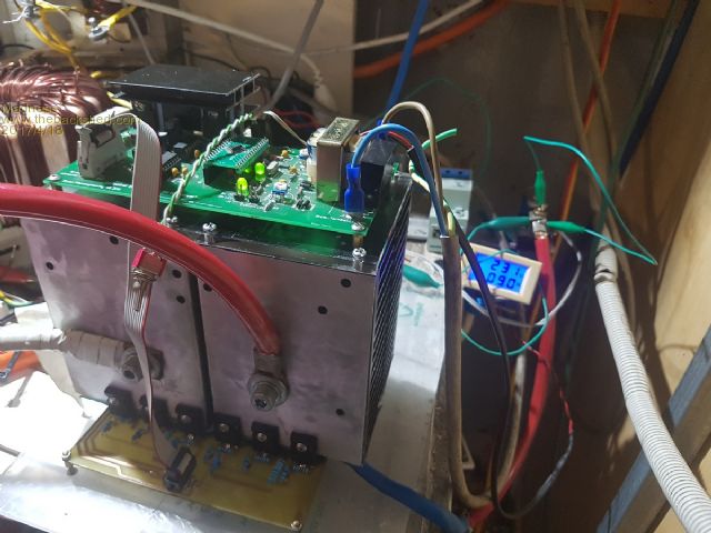 It is connected to a single core toroid and a 65mm ecore choke with 3.5 turns. Here is no load, idle current is about 20W. 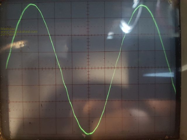 And 9A @230V fan heater load, runs very cool, no fans and the heatsink just got to 10 degrees above ambient.. 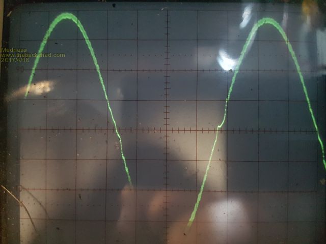 Only parts in common with my big inverter is the battery bank and the Oscilloscope. I will try a few different choke setups to see if it will improve. There are only 10 types of people in the world: those who understand binary, and those who don't. |
||||
oztules Guru Joined: 26/07/2007 Location: AustraliaPosts: 1686 |
Nice little unit. I expect it would drive a normal house just fine. If it does not get hot... ignore the waveform, see how it runs longer term if you can keep the house loads under say <4kw for 10 minute periods, and <2kw for most of the time. That would be most houses off grid. Check the leg connection of the 8010 to the circuit board.... maybe intermittant fault in there somewhere when it runs for 10 days and fails. What was the sine wave like when the heats sinks were not attatched? ........oztules Village idiot...or... just another hack out of his depth |
||||
Madness Guru Joined: 08/10/2011 Location: AustraliaPosts: 2498 |
My plan is to put it in a single case and eventually be a backup Inverter. In the meantime, I want to see how it goes with a GTI connected. I have not tried it with no heat sink, I did put it on one of my really big heatsinks and it performed the same, won't take much to try with no heat sink. There are only 10 types of people in the world: those who understand binary, and those who don't. |
||||
| Warpspeed Guru Joined: 09/08/2007 Location: AustraliaPosts: 4406 |
Klaus, Neglecting any resistance, if you switch 48v across an 0.7uH inductance, the rate of current rise is going to be about 69 amps per microsecond. At 20Khz, with full 50%/50% duty cycle the on time will be 25uS. A peak to peak ripple current of 25uS x 69 amps = 1,725 amps peak to peak is theoretically possible. That is well into "GO BANG" territory. Cheers, Tony. |
||||
Madness Guru Joined: 08/10/2011 Location: AustraliaPosts: 2498 |
I have made some progress with this in a number of areas. I changed the choke to a ferrite ring, I got the best result with 2 turns from the SPWM side of the inverter and one from the other side, Idle current went up a little to around 25 watts but the waveform is better. 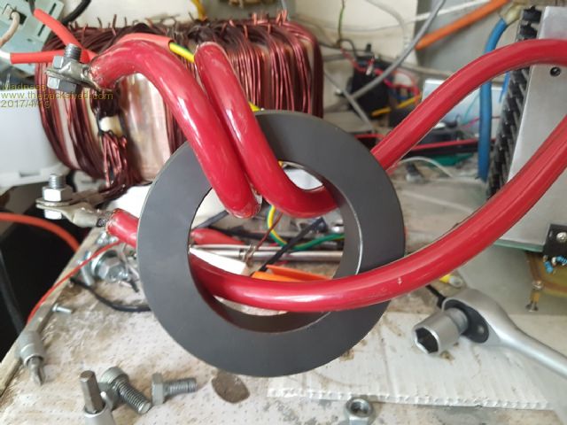 No Load 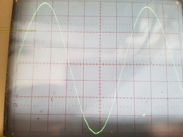 Under Load 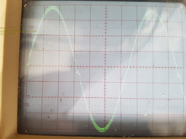 After making these changes I tried the GTI on it and it failed again so I changed the GTI main PCB and IGBT driver boards and it now works with this inverter. Then I tried it with the big inverter and it failed after only 30 seconds or so under load. Later I will transfer the Ferrite to the big Inverter and see how it behaves with the GTI. There are only 10 types of people in the world: those who understand binary, and those who don't. |
||||
Madness Guru Joined: 08/10/2011 Location: AustraliaPosts: 2498 |
I found what was causing the GTI to fail, the 600W UPS I had connected to my electronics in the house. Removed it and the GTI and my big Inverter are now playing nicely together. There are only 10 types of people in the world: those who understand binary, and those who don't. |
||||
| Tinker Guru Joined: 07/11/2007 Location: AustraliaPosts: 1904 |
Gary, what dead time are you using now? The above inductance explanation from Tony has me wondering now if making the primary with 90mm sq wire was perhaps not so good an idea. Looking up the inductance formula, the wire area does play a part here. What primary winding wire area do you use now? Klaus |
||||