|

|
Forum Index : Microcontroller and PC projects : Beta Testers Wanted
| Author | Message | ||||
| JohnS Guru Joined: 18/11/2011 Location: United KingdomPosts: 3819 |
What's thee next chip up that is nearly the same as the one(s) for the umite but has more free flash? Does it cost much more / would it be a better choice? John |
||||
| hitsware Guru Joined: 23/11/2012 Location: United StatesPosts: 535 |
> Add Geoff's VT100 chip, that he posted is coming, > and you don't even need a PC to program it. Monitor and keyboard to VT100 chip VT100 chip to Micromite ? |
||||
elproducts Senior Member Joined: 19/06/2011 Location: United StatesPosts: 282 |
In a DIP package, the MicroMite PIC32 MX1/2 chip is the largest memory Microchip offers. www.elproducts.com |
||||
| JohnS Guru Joined: 18/11/2011 Location: United KingdomPosts: 3819 |
Oh :( Thanks. John |
||||
elproducts Senior Member Joined: 19/06/2011 Location: United StatesPosts: 282 |
In an earlier post to this topic Geoff wrote: The editor is important as it means that someone does not need specialised software (like MMEdit) to change a program. Also, it will work with another project of mine that is in the pipeline (a VT100 terminal based on the PIC32MX250). I based that on Geoff's post so I might be wrong in my assumption that this means no computer is required. Just a MicroMite chip and a VT100 chip. It will be interesting when those details are available. www.elproducts.com |
||||
James_From_Canb Senior Member Joined: 19/06/2011 Location: AustraliaPosts: 265 |
Although a higher spec non-DIP chip could be mounted in a DIP adapter. Maybe only the subset of pins used for the micromite could be connected, so it keeps the 28 pin format. James My mind is aglow with whirling, transient nodes of thought careening through a cosmic vapor of invention. Hedley Lamarr, Blazing Saddles (1974) |
||||
| vasi Guru Joined: 23/03/2007 Location: RomaniaPosts: 1697 |
Although a higher spec non-DIP chip could be mounted in a DIP adapter. Maybe only the subset of pins used for the micromite could be connected, so it keeps the 28 pin format. James But then, there will be enough memory to support the chip completely. I'm sure Geoff will extend Micromite but patience, let's have this one up and running. ___ Then, "micro" from the name will mean microcontroller, and not something minuscule. Hobbit name: Togo Toadfoot of Frogmorton Elvish name: Mablung Miriel Beyound Arduino Lang |
||||
Grogster Admin Group Joined: 31/12/2012 Location: New ZealandPosts: 9310 |
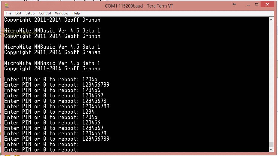
Possible bug? When entering the PIN number, the manual clearly states that it should be less then six(6) characters. While any PIN number up to six characters works fine, you can still enter a PIN longer then six characters, the MM accepts it, prompts you for it, then you are locked out of the MM forever. 
I would assume this is simply because I have exceeded the allowed length of the PIN number. 
In my case, I used a PIN of 123456789: option pin 123456789 MM responded with: > Cycle power, MM asks for PIN number, which never works again. 
I know I have killed it through my own experiment, but I will now reset MMBasic as per the manual, but if this is indeed a bug, it would be a good idea if the MM simply said "Rejected." or something, if the PIN is too long when entered with the OPTION PIN command. My 2c only..... Smoke makes things work. When the smoke gets out, it stops! |
||||
Grogster Admin Group Joined: 31/12/2012 Location: New ZealandPosts: 9310 |
Resetting MMBasic also does not seem to want to work. This is POSSIBLY related to the above, as with the PIN being too long, perhaps that also upsets the ability for you to be able to reset MMBasic? Following the manual: - MM powered, and asking for the PIN in TT - Remove console TXD and RXD from level corrector - Short the two together while MM still powered. - Remove the short while MM still powered. - Remove power. - Replace the console TXD and RXD to the level corrector - Apply power. MM still asking for the PIN. Smoke makes things work. When the smoke gets out, it stops! |
||||
| plasma Guru Joined: 08/04/2012 Location: GermanyPosts: 437 |
Blinky Blinky Micromite |
||||
Grogster Admin Group Joined: 31/12/2012 Location: New ZealandPosts: 9310 |
The best way to start with any new microcontroller, IMHO, is exactly that - blinking and LED. Gets you used to the funademtals. With the MM IC though, I guess most of us who have programmed the mono MM or colour MM before, we can fast-track the programming of the MM chip, but I still did the blinky LED thing too yesterday. EDIT: "funademtals"?! 
I think I have just made a new word. Smoke makes things work. When the smoke gets out, it stops! |
||||
| Geoffg Guru Joined: 06/06/2011 Location: AustraliaPosts: 3199 |
Good point and I will fix it. At least this proves that you cannot do anything once the PIN has been set. On resetting the Micromite: - Remove power - Short the console Tx & Rx - Apply power - Remove short and cycle the power. Or simply put, short the console Tx & Rx while applying power. Perhaps I should clarify the wording in the manual. Geoff Geoff Graham - http://geoffg.net |
||||
Grogster Admin Group Joined: 31/12/2012 Location: New ZealandPosts: 9310 |
- Remove power - Short the console Tx & Rx - Apply power - Remove short and cycle the power. Or simply put, short the console Tx & Rx while applying power. Perhaps I should clarify the wording in the manual. Geoff Oh, makes sense now - thanks, and shorting TXD and RXD while applying power, then short off and cycle power, and the MM is back at the command prompt again. 
Yes, I was interpreting the manual as having to keep the MM powered while you do that, which I was wondering how the hell the MM could possibly detect that once up and running. 
Smoke makes things work. When the smoke gets out, it stops! |
||||
Grogster Admin Group Joined: 31/12/2012 Location: New ZealandPosts: 9310 |
I have ordered 5 of the 10mm TQFP(0.8mm pin spacing) to play with. I will make a diagram of the pins for the MM version, and if anyone is interested, they can then refer to the TQFP pinout, IF they want or need that footprint of the device. I've started using more and more SMD, and although the SOIC is perfectly suitable too, the TQFP spreads the pins out on four sides rather then two, in theory, making it easier to route tracks to the chip - bearing in mind that the TQPF device, used as a MM chip, won't use quite a few of the pins... I will keep you all posted on this one - I will have to make a prototype board for it. Smoke makes things work. When the smoke gets out, it stops! |
||||
MicroBlocks Guru Joined: 12/05/2012 Location: ThailandPosts: 2209 |
i have some 28 pin QFN ordered. they are 6x6mm. :) now looking for a programming/test socket. Microblocks. Build with logic. |
||||
Grogster Admin Group Joined: 31/12/2012 Location: New ZealandPosts: 9310 |
now looking for a programming/test socket. They are too small for me!  Smoke makes things work. When the smoke gets out, it stops! |
||||
| MOBI Guru Joined: 02/12/2012 Location: AustraliaPosts: 819 |
I'd be looking for a magnifying glass not just a socket! David M. |
||||
Grogster Admin Group Joined: 31/12/2012 Location: New ZealandPosts: 9310 |
Here is my image of the 44-pin TQFP for the MM: The IO pins from the 28-pin device are called "Pin" with the corresponding number for the 28-pin device, along with the QFP numbers. The MM pins are quite nicely spread out on all four sides of the QFP, so that should make routing traces a bit easier, as you can plan for certain things to go to the pins on that side of the chip. TXO is short for TXD out, and RXI is short for RXD in. I stole this from Sparkfun's way of labeling things - really helps to prevent confusing your TXD and RXD lines. I have yet to design a prototype PCB, but I have designed a footprint for the IC, I just want to wait till the chips actually arrive, so I can check that I have it right before I start any other design. Plenty of other stuff to go on with anyway!  Smoke makes things work. When the smoke gets out, it stops! |
||||
MicroBlocks Guru Joined: 12/05/2012 Location: ThailandPosts: 2209 |
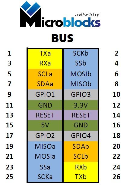
I have actually defined a connector for my MicroBlocks and i will have to go through the same steps mapping pins. The connector looks like this: 
This connector can be used with straight connectors to stack boards or to plug them next to eachother on a backplane. When using 90 degree connectors you can use a backplane where the connectors are place closer together. Or any combination of them. My 'MicroBlocks' will use the straight connectors and a backplane. The connector is defined such that you use only what you need. All possible uses where the connector has no gaps between pins are worked out in this pdf: 2014-01-27_101631_Microblocks_BUS.pdf The purpose of this connector is to use bus type signals, which allow parallel use. Especially I2C and SPI, together with some UART, and GPIO to easy the development of blocks that need additional signals, A GPIO can also be used as a 1-wire. The prefered one is GPIO1 The location of this connector should be on the left or right of the pcb. Specific pins on the top and bottom. In the case of the MicroMite i would connect all pins to the right side, and specific pins like the ones used for the console on the top. Other IO on the bottom. I will have a layout ready tomorrow. Maybe it suits your needs. And it will be compatible with future MicroBlocks. Microblocks. Build with logic. |
||||
MicroBlocks Guru Joined: 12/05/2012 Location: ThailandPosts: 2209 |
an update to my tera term problems. On other computers it works great. i have pinned it down to a usb port, because the other computer is configured the same, also same driver versions. there probably is no fix, maybe an update for the motherboard, but i doubt it. Microblocks. Build with logic. |
||||