|

|
Forum Index : Microcontroller and PC projects : PicoMite V6.00.01 release candidates - please test thoroughly
| Author | Message | ||||
| matherp Guru Joined: 11/12/2012 Location: United KingdomPosts: 9290 |
OK: nothing to do with "/ it is an artifact of the 'end "something"' functionality which I've fixed in my dev environment |
||||
| JanVolk Senior Member Joined: 28/01/2023 Location: NetherlandsPosts: 166 |
Peter, I tried again today the GUI TEST LCDPANEL and now it works fine and I can stop the test with any key on my keyboard. Repeated yesterday's actions, but can no longer recreate the problem. I had done the same as Volhout to change RLANDSCAPE -> LANDSCAPE. After a reset everything works fine again. (The GEEK has no reset, so take the module out and put it in) Therefore, I tested flashing the firmware again, but the problem no longer occurred, so it remains a vague problem. Greetings, Jan. |
||||
| Volhout Guru Joined: 05/03/2018 Location: NetherlandsPosts: 4344 |
OK, I figured it out. It was caused by a missing END statement. Earlier versions where ignorant to it. This rc8 apparently not. Volhout PicomiteVGA PETSCII ROBOTS |
||||
| Peter63 Newbie Joined: 28/07/2017 Location: SwedenPosts: 16 |
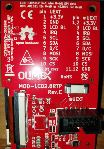
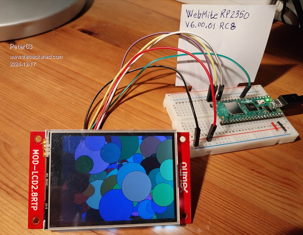
Hello, from Sweden I have tested this display, works OK. But how do I connect cables for touch?  Peter |
||||
| homa Guru Joined: 05/11/2021 Location: GermanyPosts: 379 |
@Peter63 I got this from the website: - LCD uses SPI, touch uses I2C or UART - Touch is handled by NS2009 or AR1021 depending on hardware revision https://www.olimex.com/Products/Modules/LCD/MOD-LCD2-8RTP/open-source-hardware https://github.com/OLIMEX/MOD-LCD2.8RTP/blob/master/README.md 5 - SCL 6 - SDA I2C pins used for touch component But the whole thing would be better off in its own thread. Matthias Edited 2024-12-17 02:44 by homa |
||||
| Peter63 Newbie Joined: 28/07/2017 Location: SwedenPosts: 16 |
Hello U2 chip is the NS2009, for touch I2C GUI TEST LCDPANEL works OK I'm going to test some more, and see if I can get the touch function to work...  Peter |
||||
| WhiteWizzard Guru Joined: 05/04/2013 Location: United KingdomPosts: 2838 |
Hi Peter/Geoff, Have set up a genuine Pico 2 with VGA RC8, and am accessing it via TeraTerm (for keyboard input) and have both a vga monitor and the TeraTerm screen for viewing ‘output’. I have set OPTION LCDPANEL CONSOLE 3,RGB(GREEN),RGB(BLACK) so it defaults to green-on-black in (large) font 3. The hope was that this would increase the size of the font in the editor as well as at the command-prompt. All is good for the command prompt (and on reset) but if I enter the EDITOR then it reverts back to a small font (font 1?); and on returning to the command-prompt (from the editor) the font is small once again (ie not the default font 3 requested as per option setting). Question/Suggestion: 1) is there anyway to configure the font used for the editor rather than it being fixed at 40 lines of 80 characters (which is too small under certain circumstances). This can be adjusted for non-vga/hdmi versions of firmware by OPTION DISPLAY but this setting is not available for vga/hdmi firmware 2) would it not make sense to have a default (and persistent) font size (and colour) for the command-prompt mode, and likewise another persistent default setting for the editor. Only in program-run mode does it change as per program-code. Then on exiting run-mode it reverts to the command-prompt font size & colour (and on entering the Editor reverts to the editor default font size &colour (or colour code if that option is set). Hope this makes sense….. (forgot to mention this logic can work for all versions of the firmware and gives the user total control as to the look & feel of the display) Edited 2024-12-17 03:30 by WhiteWizzard For everything Micromite visit micromite.org Direct Email: whitewizzard@micromite.o |
||||
| ville56 Senior Member Joined: 08/06/2022 Location: AustriaPosts: 118 |
if I understand the datasheets right, then there is no IRQ for the touch available on the connector. This would reduce usability a lot. But I may be wrong.... 73 de OE1HGA, Gerald |
||||
| Volhout Guru Joined: 05/03/2018 Location: NetherlandsPosts: 4344 |
Hi Whitewizzard, The editor 80x40 screen and font #1 are result from the VGA version of the 2040. The VGA screen has tiles (8x12) to color individual characters in the editor. There is not enough RAM for pixel colors. The tiles have a fixed width of 8. If firmware can remember what font was used before -and after- editing is a feature. But during editing the VGA is stuck to 80x40 and font 1, and a result of colourcoding. Volhout Edited 2024-12-17 04:38 by Volhout PicomiteVGA PETSCII ROBOTS |
||||
| WhiteWizzard Guru Joined: 05/04/2013 Location: United KingdomPosts: 2838 |
Before I test the HDMI RC8, can anyone (Volhout?) confirm if the editor has 80 characters by 30 lines; in other words if it uses the same 8x12 size tile (as in the vga version) in its 640x360 screen. Thanks…. For everything Micromite visit micromite.org Direct Email: whitewizzard@micromite.o |
||||
| phil99 Guru Joined: 11/02/2018 Location: AustraliaPosts: 2180 |
You can switch to TeraTerm only for console / editor output with:- OPTION LCDPANEL NOCONSOLE That allows:- OPTION DISPLAY lines, char. To get program output on both screens however requires both PRINT and TEXT statements. |
||||
| WhiteWizzard Guru Joined: 05/04/2013 Location: United KingdomPosts: 2838 |
Thanks Phil99 for your post. I am ultimately creating a standalone unit for ‘education’ purposes with some neat little features (hence my many recent posts). TeraTerm is only being used as a debugging interface whilst exploring any limitations of the set-up. Even though I have made great progress using VGA, I’m feeling that HDMI may be a better choice for a better user experience. Once everything is finalised, I intend to write a series of magazine articles for ‘Practical Electronics’ magazine - possibly called ‘Make it with PicoMite’ For everything Micromite visit micromite.org Direct Email: whitewizzard@micromite.o |
||||
| javavi Senior Member Joined: 01/10/2023 Location: UkrainePosts: 297 |
In PicoMiteHDMI RP2350 in MODE 1 640x480x2 programs using FRAMEBUFFER for copying shadow frame do not work (or rather they work, but do not show anything). Although on the PicoMiteVGA RP2040 version in MODE 1 640x480x2 it works. Is it possible to make the shadow FRAMEBUFFER work the same way in MODE 1 on both variants, for VGA and for HDMI (RP2350)? MODE 1 FRAMEBUFFER CREATE FRAMEBUFFER WRITE F CX=MM.HRes\2: CY=MM.VRes\2 A=CX*5: C=RGB(White) Do :CLS For i=7 To 31 Step 3 For j=0 To 324 Step 9 x=CX+A*Sin(j+i+t*i/200)\i y=CY+A*Cos(j+i*0.3+t/2)\i If j=0 Then Circle x,y,3,,,,C Pixel x,y Next : Next t=t+.05:Circle CX,CY,9,,,,C FRAMEBUFFER COPY F,N,B Loop Until Inkey$ <> "" |
||||
| matherp Guru Joined: 11/12/2012 Location: United KingdomPosts: 9290 |
Thanks for the report - will have a look at it |
||||
| WhiteWizzard Guru Joined: 05/04/2013 Location: United KingdomPosts: 2838 |
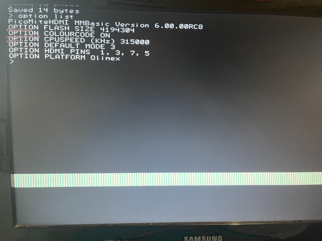
 On exiting the editor (whether making changes to code or not, or by using F1, F2 , Esc or Ctrl-C) I get the following appear near the bottom of the screen all the way across. For everything Micromite visit micromite.org Direct Email: whitewizzard@micromite.o |
||||
| WhiteWizzard Guru Joined: 05/04/2013 Location: United KingdomPosts: 2838 |
With OPTION DEFAULT set to either 1024 or 1280, setting OPTION DEFAULT MODE 4 causes the HDMI display to show no signal (black screen). It is not hanging the HDMI Pico as Tera-Term is still interactive. Could this be a monitor syncing issue OR is it a 'feature' (I only have one HDMI monitor where I am at the moment). NOTE: If resolution is set to 640 then MODE 4 works. Also, all other modes (1,2,3, and 5) all work across all resolutions. For everything Micromite visit micromite.org Direct Email: whitewizzard@micromite.o |
||||
| matherp Guru Joined: 11/12/2012 Location: United KingdomPosts: 9290 |
Replicate on 6.00.01RC8 and I'll have a look |
||||
| WhiteWizzard Guru Joined: 05/04/2013 Location: United KingdomPosts: 2838 |
(the issue on exiting the EDITOR shown in the screenshot in the above post seems to be when OPTIONs RESOLUTION = 640 and MODE = 3. On using other 'random' settings it works ok) For everything Micromite visit micromite.org Direct Email: whitewizzard@micromite.o |
||||
| matherp Guru Joined: 11/12/2012 Location: United KingdomPosts: 9290 |
javavi This should fix it. Bug in CLS for mode 1 on HDMI only not respecting FRAMEBUFFER WRITE PicoMite.zip |
||||
| matherp Guru Joined: 11/12/2012 Location: United KingdomPosts: 9290 |
That's because mode 4 isn't valid for 1024 or 1280 - try just using the mode command. I'll block it for OPTION DEFAULT MODE The issue is that you are using out-of-date firmware based on your screenshot 6.00.00RC8 NOT 6.00.01RC8 |
||||