
|

|
Forum Index : Electronics : A newbie ozinverter build
| Author | Message | ||||
| gaspo Regular Member Joined: 25/06/2018 Location: AustraliaPosts: 65 |
Thanks Tinyt for the brief review  I assume that you increase the rotation speed with thicker wire. I think I'm going to get one from AU Ebay (currently at $65). I'm not really looking forward to manually strip ends of many ten's of wires with a blade. |
||||
| tinyt Guru Joined: 12/11/2017 Location: United StatesPosts: 438 |
There are 3 cutters. One end of each cutter has the cutting tip that digs into the insulation. The other end is some sort of a weight. There is a pivot in the middle. The 3 cutters are arranged in a circle by their pivots. To setup the speed, initially start with slow rotating speed. If the rotating speed is low and you are stripping small diameter wires, you have to increase the speed so that the weight will move out and the tips will move in towards the center of rotation where the wire is. Slowly increase the speed until the tips barely touch the wire insulation. At this point you increase the speed slightly. If it is too fast, you will feel the tool pulling the wire, so back off on the speed . Then you pull opposite for the tips to remove the insulation. If you pull too fast, the tips will just make spiral cuts on the insulation. If the rotation speed is too high, the tips will dig too deep and into the copper which you do not want to happen. For each wire size and insulation type, I had to practice on sample wires first to get the right speed and also pulling rate. |
||||
| Tinker Guru Joined: 07/11/2007 Location: AustraliaPosts: 1904 |
I had looked at it too when tinyt first mentioned it. But the price put me off  . Even if you had 100 wires to strip, each strip would still be 65 cents.... . Even if you had 100 wires to strip, each strip would still be 65 cents....I can see why tinyt bought one for his rather thin wire, many strand, coils. I wonder if he bought two or three packets of patience as well   . .The stripping method, thanks for explaining it so well tinyt, is clever but I wonder how it copes with wire that is not perfectly straight. For example, the 1.8mm diameter wire I used to wind the toroid (and chokes) was recycled wire and well straightened. But the ends after winding the coil are not quite straight any more and, being shortish, would not be easy to *perfectly* straighten. So, if that tool can cope with that so much the better. Gaspo, I agree that manually stripping the enamel of the wire is a pain but having done quite a few ends by now the task does get easier with practice. Klaus |
||||
| tinyt Guru Joined: 12/11/2017 Location: United StatesPosts: 438 |
So I tested the toroid in autotransformer mode with 3.5kw load for 1 hour. Core temperature went up to about 47 deg. C. No anomalies, idle current is still 0.055A. So it not the toroid and must be something else. I modified the EGS002 to operate in bipolar mode (EG8010 chip pin 20 to +5vdc). The sinewave is ugly: Looks like the EGS002 is not designed for it, maybe its cross-conduction transistors were messing it up. I don't know if anybody tried bipolar with the EG8010 pcb. Went back to unipolar and re-scoped: And kept staring at it until I became cross-eyed. Then it hit me that the non-symmetry could be causing flux walking especially when I was testing a toroid core rated for 2.5kw at over its rating. Maybe the overload for an extended period of time is exacerbating it. I don't know, I know nothing about magnetics. So now I am abandoning the EGS002 and EG8010 and will be going the arduino way. Hopefully, I can understand what the experts like poida, gaspo, wiseguy and others are talking about. |
||||
| tinyt Guru Joined: 12/11/2017 Location: United StatesPosts: 438 |
After a one month hiatus, my wife has started to ask about progress of this project. So I did some testing and found out that one of the IR2010 SPWM output starts at slightly low voltage from zero crossing and then flattens out to normal for the rest of the half sine. I replaced it and now the kink in the waveform is no longer discernible. This is with 3.4kw load. 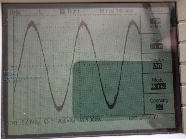 So, I continued testing this EGS002 inverter with the existing toroid. First I setup for two 2.2kw stove heating elements in parallel for load, It runs for about 30 seconds and then shuts down with under voltage LED flashing. Note that the EGS002 is not being fed by IFB. I scoped the AC output prior to shutdown together with the SPWM and set the scope time base to 50 ms. 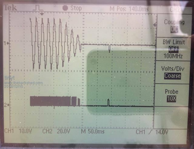 Top trace is AC output, bottom trace is SPWM. Note that the AC ouput starts to drop but the SPWM is still maintained for about 90 milliseconds, and then shuts off after about 100 milliseconds. I think that blip after shutdown was also noticed by wiseguy. Here are values before the shutdown: Input DCV: 54.3V Input Amps: 90.7A Input Watts: 4925 watts Output ACV: 229VAC Output Amps: 18.92A Output Watts: 4332.7 watts Efficiency: 88% The toroid is a re-wound manufacturer rated 2.2kw transformer. My conclusion is that the toroid core is saturating at this overload level. I explained this to my wife. Either I explained it well or she understood everything completely as she only says three words to me - You are crazy st....! So back to temperature testing at slightly lower overload condition - 3.4kw: Starting values: Input DCV: 53.2V Input Amps: 70.4A Input Watts: 3745.3 watts Output ACV: 229VAC Output Amps: 15.17A Output Watts: 3473.9 watts Efficiency: 92.8% Here is temperature data every minute for one hour: Col1: minute count, Col2: Heatsink Temp. Col3: Toroid Temp. 1, 28, 17,0,875 2, 31, 18,0,875 3, 34, 18,0,875 4, 36, 19,0,875 5, 38, 19,0,875 6, 41, 20,0,875 7, 42, 20,0,875 8, 43, 21,0,875 9, 43, 21,0,875 10, 45, 22,0,875 11, 45, 22,0,875 12, 46, 22,0,875 13, 47, 23,0,875 14, 48, 23,0,875 15, 49, 24,0,875 16, 49, 24,0,875 17, 49, 25,0,875 18, 49, 26,0,875 19, 51, 26,0,875 20, 51, 27,0,875 21, 52, 27,0,875 22, 51, 27,0,875 23, 52, 28,0,875 << forced air cooling to heatsink started 24, 48, 28,0,875 25, 45, 29,0,875 26, 42, 29,0,875 27, 41, 29,0,875 28, 40, 29,0,875 29, 39, 30,0,875 30, 38, 30,0,875 31, 37, 30,0,875 32, 38, 30,0,875 33, 38, 31,0,875 34, 37, 31,0,875 35, 36, 31,0,875 36, 37, 31,0,875 37, 36, 32,0,875 38, 37, 32,0,875 39, 38, 32,0,875 40, 39, 33,0,875 41, 39, 33,0,875 42, 38, 33,0,875 43, 37, 33,0,875 44, 38, 34,0,875 45, 37, 34,0,875 46, 37, 34,0,875 47, 37, 35,0,875 48, 37, 35,0,875 49, 37, 35,0,875 50, 37, 35,0,875 51, 37, 35,0,875 52, 37, 36,0,875 53, 37, 36,0,875 54, 36, 36,0,875 55, 36, 37,0,875 56, 36, 37,0,875 57, 36, 37,0,875 58, 36, 37,0,875 59, 36, 37,0,875 60, 36, 37,0,875 61, 36, 38,0,875 62, 36, 38,0,875 63, 36, 38,0,875 64, 36, 38,0,875 65, 36, 39,0,875 66, 36, 39,0,875 67, 36, 39,0,875 68, 36, 39,0,875 69, 37, 40,0,875 70, 36, 40,0,875 71, 37, 40,0,875 72, 37, 40,0,875 I used a household fan to start forced air cooling to heatsink at the HS temperature of 52 deg after 23 minutes. Ending values: Input DCV: 53.5V Input Amps: 69.8A Input Watts: 3734.3 watts Output ACV: 230VAC Output Amps: 14.82 Output Watts: 3408.6 watts Efficiency: 91.3% Here is a picture of my testing. 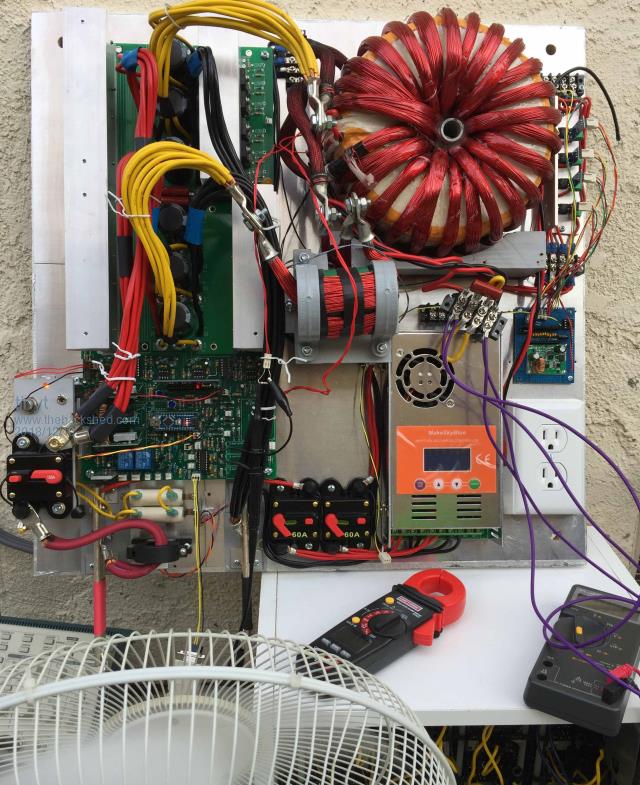 EI choke was only warm to the touch. Also, for this size inverter, I think a fabricated heatsink is adequate. I am now happy with my testing and will complete the assembly. |
||||
renewableMark Guru Joined: 09/12/2017 Location: AustraliaPosts: 1678 |
Nice work mate, that's quite an effort doing all that from scratch. Cheers Caveman Mark Off grid eastern Melb |
||||
| tinyt Guru Joined: 12/11/2017 Location: United StatesPosts: 438 |
Thanks, I learned a lot. Will be learning more when I do the PV's, monitoring, LCD, logging, completing the cabinet, battery rack, etc., etc. |
||||
| johnmc Senior Member Joined: 21/01/2011 Location: AustraliaPosts: 282 |
Terrific effort tinyt It gives a lot of help and satisfaction, as we watch your inverter come to life. It also appears that their is no end to the new frontiers that we cross when playing with inverters. cheers john johnmc |
||||
| Ralph2k6 Senior Member Joined: 24/09/2017 Location: AustraliaPosts: 129 |
Nice job! Can't wait to see an update with it in a nice enclosure next. Has been quite a journey, thanks for keeping us 'in the loop'.  Ralph |
||||
| tinyt Guru Joined: 12/11/2017 Location: United StatesPosts: 438 |
Right now I have 4 strings of 4 100-watts solar panels (1.6kw total). I want to monitor the voltage and current flow for each string. This is the connection schematic.2018-12-18_063648_Solar_Array_Combiner_and_Sensor.pdf I hope it works. If it works and when I have extra money, I will install another identical array, hence the reference to nano3. |
||||
renewableMark Guru Joined: 09/12/2017 Location: AustraliaPosts: 1678 |
Hey mate, do you get many second hand panels on the market over there? I always keep an eye on house demolition sales, that's where I got most of my panels. Cheers Caveman Mark Off grid eastern Melb |
||||
| tinyt Guru Joined: 12/11/2017 Location: United StatesPosts: 438 |
There probably are available, sellers sometimes post them on craigslist. But I did not go that route. When I started this project, I knew nothing about solar (PV). I am short, small in built, and cannot lift large and heavy panels, so I just bought RV sized panels from renogy And I just installed them without any help. I don't have a backyard to put them. Here is satellite view of the roof install. 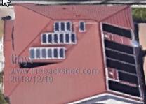 Left (west) is the front of the house and the wife wants them hidden from view as much as possible, so any addition has to go on the north facing side. The black panels are solar pool heaters which I also installed about 15 years ago. |
||||
| johnmc Senior Member Joined: 21/01/2011 Location: AustraliaPosts: 282 |
Good day tinyt, How did you get the satellite image to cover such a small area ? We live out of town and the smallest satellite image I can get, is about 4 acres. cheers john johnmc |
||||
| Boppa Guru Joined: 08/11/2016 Location: AustraliaPosts: 814 |
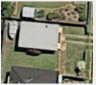 That's my 4.2m boat behind the garage (1 1/2 car wide) and if you look closely, you can actually see the little 10w tandy solar panel on the garage roof which is about 30cm x 20cm and kept the battery charged for the boat lights and other batterys In many places, things like google earth's 'satellite view' are actually from commercially available aerial shots from planes, so if you have a closeup, thats from a plane- the ones where a house id barely a dot, thats actual satellite shots in most cases That shot is actually very old indeed, the boat now lives at the other end of the house and my ute lives there where the boat was, the roofs been replaced on the house, solar hws and panels have been added- so it was taken at least five years ago- jeez the hws is due for an anode replacement and it wasn't even there in that shot- google can be slow.... 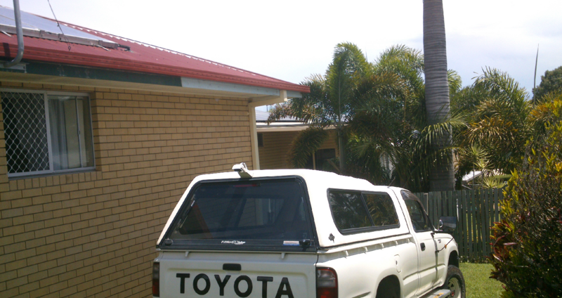 thats the new roof with hws, and you can see the bush next to the garage on the right |
||||
| tinyt Guru Joined: 12/11/2017 Location: United StatesPosts: 438 |
Thanks Boppa, I think you are correct. That first roof view I posted came from google maps - satellite view, the other choice is map view. When I tried google satellite, I got this which is smaller and does not yet have the PV panels.  So, I think google maps should clarify what kind of view it is. |
||||
| tinyt Guru Joined: 12/11/2017 Location: United StatesPosts: 438 |
OK, started to complete the enclosure assembly. Here are the side panels. They are made from pre-painted pine wood about 19 mm thick. 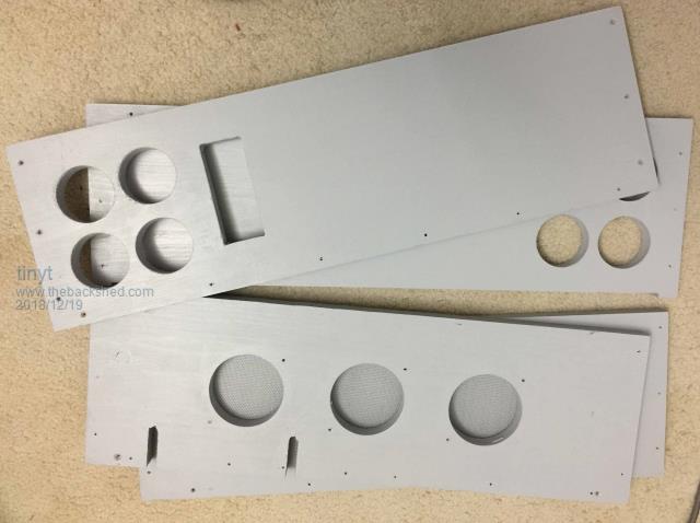 Here are the inside surface views of the bottom and top panels showing the aluminum sheets. The sheet are glued with contact cement and then nailed with wire brads. 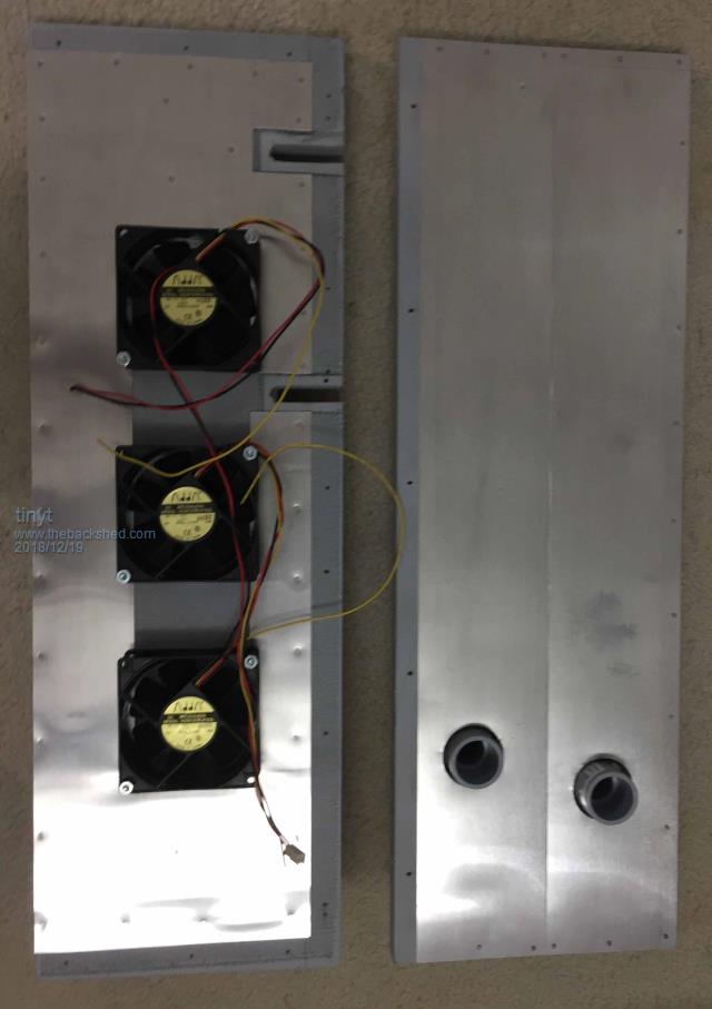 Here are the outside surface views of the bottom and top panels. The bottom has a screen to prevent insects from entering. The top has utility boxes to feed in the solar array wires. The second box is for future install of a second solar array. The bottom panel is closer to the camera, making it look longer than the other one. 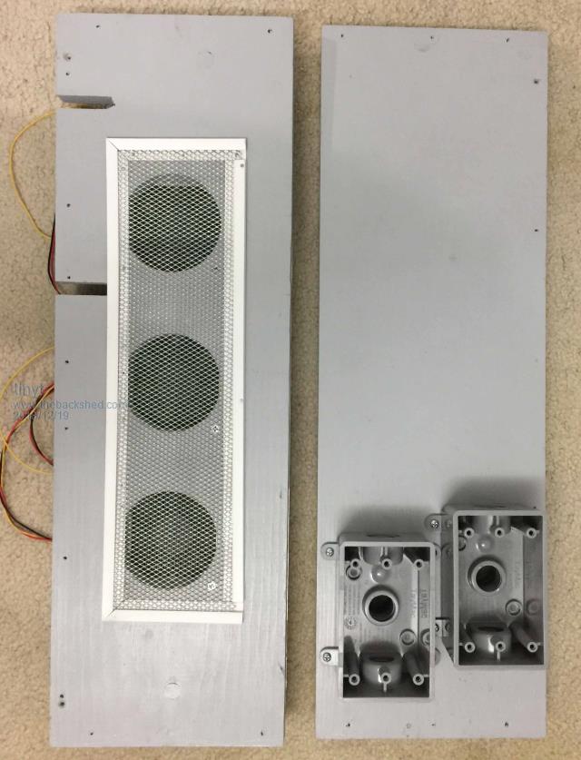 Here are the inside surface views of the left and right panels. The white rectangular things are magnetic latches to hold the cover closed. There is a spring return switch (automotive hood/door switch) which will be used to switch on/off +5v to the LCD display so that the display gets power only if the enclosure cover is open. 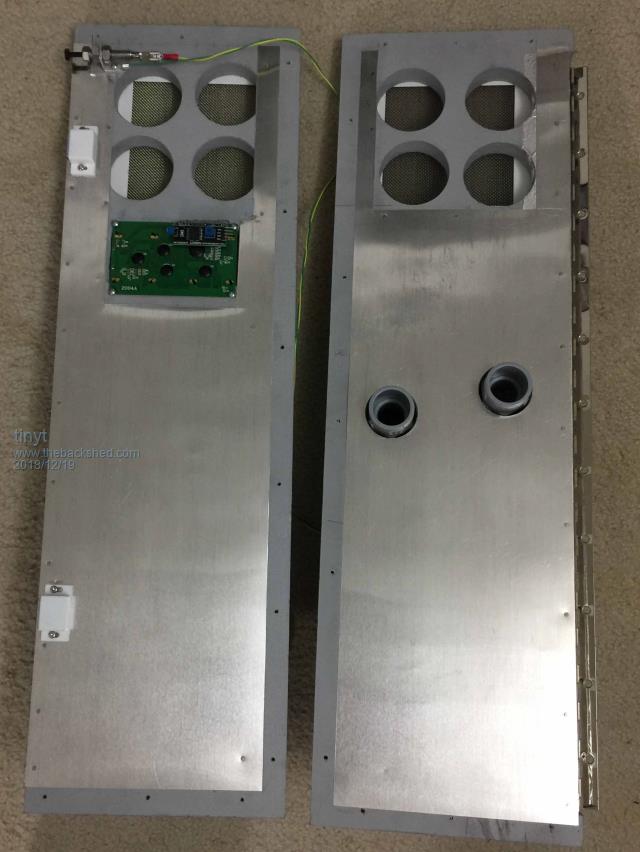 Here are the outside surface views of the left and right panels. The LCD opening has a clear acrylic sheet cover. The black border framing the LCD display border is just paint. Utility boxes are for load wiring. 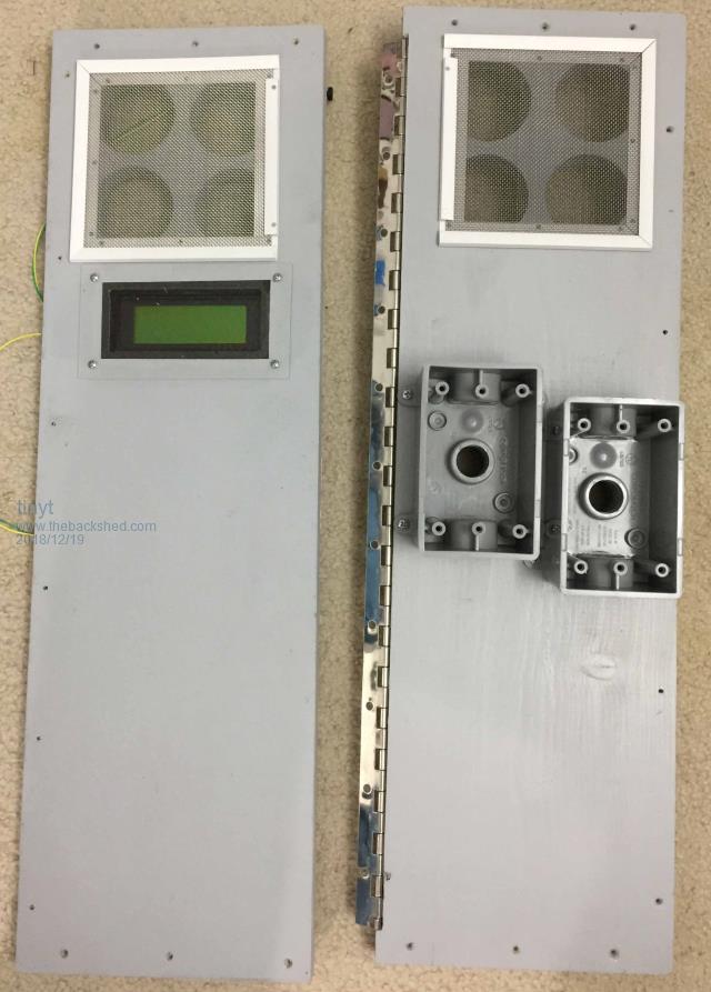 I am still working on the cover which is made of plywood with hardwood border. It will also have aluminum sheet on the inside surface and will be attached to the right panel using piano hinge. |
||||
| Ralph2k6 Senior Member Joined: 24/09/2017 Location: AustraliaPosts: 129 |
Very professional there tinyt! Keep up the great work  Ralph |
||||
| Tinker Guru Joined: 07/11/2007 Location: AustraliaPosts: 1904 |
And I though I went to a lot of trouble making my inverter cases  You win that one tinyt - by a long way. Klaus |
||||
| Ralph2k6 Senior Member Joined: 24/09/2017 Location: AustraliaPosts: 129 |
You did set the bar pretty high already Klaus.  Ralph |
||||
| tinyt Guru Joined: 12/11/2017 Location: United StatesPosts: 438 |
Update, fabricated the battery rack. Materials used: 1. Zinc plated steel slotted angle bar, 38 mm x 38 mm x 1.2 mm thick 2. Pop rivets 3. Steel wheel casters 4. Simpson Strong-Tie 18-Gauge Galvanized Steel Angle (for caster mounting) 5. Pre-painted pine wood 19 mm x 38 mm cross section (for battery spacer) 6. Scrap pieces of steel strut channels (for caster mounting stiffener) 7. Scrap aluminum square tubing, 19 mm ( for rack handles) 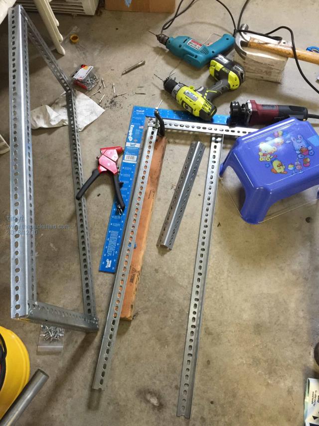 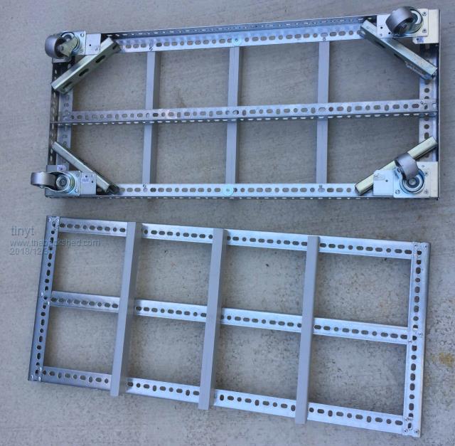 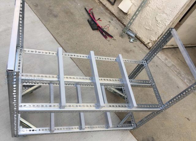 I hope it is strong enough to support the battery weight, |
||||