|

|
Forum Index : Electronics : 6Kw Ozinverter build
| Author | Message | ||||
renewableMark Guru Joined: 09/12/2017 Location: AustraliaPosts: 1678 |
I haven't, bet someone has though. What are you planning you crafty old bugger? Edit mad posted while I was typing Cheers Caveman Mark Off grid eastern Melb |
||||
| Warpspeed Guru Joined: 09/08/2007 Location: AustraliaPosts: 4406 |
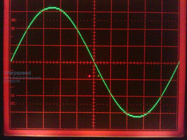
I just cannot help myself, always thinking up new projects, new and different ways of doing things. So far I have built several of these multistep sinewave inverters over the years, a very different approach to the much more popular PWM way of doing things. I might have a go at a more powerful version probably about 4.5Kw or so, that does not require the high voltage dc to dc converter stage I have been using up to now. There would be four simple square wave inverters, 3Kw, 1Kw, 330 watts and 110 watts. That requires four transformers each with 100v primaries (as I am using a 100v thirty cell Lithium battery). Combined they would produce a beautiful clean 4.5Kw 240v sinewave. The Aerosharp 3Kw toroid is looking to be perfect for the largest transformer just as it is, it should have about a 100 volt primary and a 240 volt secondary which would be perfect. The second transformer needs to be about 1Kw and have a 100 volt primary and an 80v secondary. I just realised that I can use an Inspire 1.5Kw toroid for that, turned backwards, with the original primary used as the secondary and just rearranging the original top secondary winding as the new primary which should be fairly easy to do. Third transformer needs to be 100v to about 26v, and I bet I can find some American toroid of about 300 to 400 watts that could be modified fairly easily as well. It all hinges on finding suitable already wound toroidal transformers, especially the larger ones, that I can either use as is, or after some very minor modification. I have thought this all through and it now seems fairly straightforward and practical. For those not familiar with multistep inverters, this is a picture I took about a month ago when I was playing around with my new document camera. There are 81 steps peak to peak and this was taken by poking a 1000:1 CRO probe into the mains active (100v/div on screen). I don't really need a larger inverter, but this new one would have some iinteresting unique features and new ideas I would like to try out, and that is where the appeal is. Mucking about with something fairly unique and trying out something new.  Cheers, Tony. |
||||
| Tinker Guru Joined: 07/11/2007 Location: AustraliaPosts: 1904 |
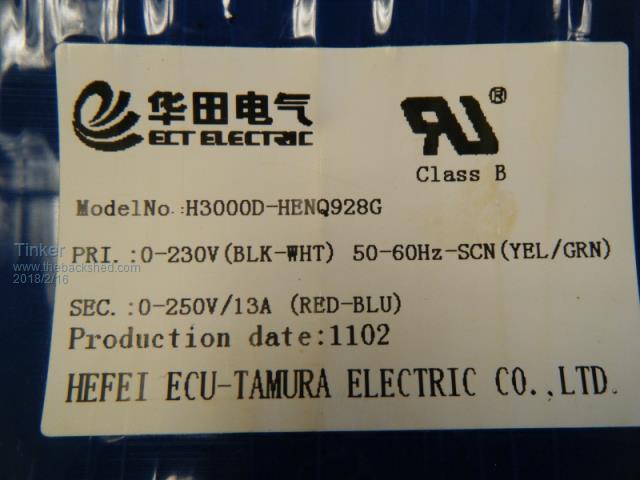
Tony, I had 3 off 3Kw ex Aerosharp toroid transformers for my inverter projects and none of these had a 100 Volt winding. They all had a 230V and a 250V winding. Its not so bad trying to do a little re winding, if the higher volt winding is on the outside you could just unwind enough turns to leave a 100v winding. Unfortunately it most likely is wound 3 in hand or so, so if it was me I'd take all of the outside winding off and re wind it 3 in hand for 100V. Klaus |
||||
| Warpspeed Guru Joined: 09/08/2007 Location: AustraliaPosts: 4406 |
I am sure you are right Klaus. But I found some Aerosharp specifications here : http://epswa.com.au/docs/Aerosharp%20Inverters.pdf They say dc input voltage range 150v to 400v for all sizes. And for the 3Kw unit 150v at 10+10 amps input, which would be about right for 3Kw. If that 150v minimum is correct, the primary would be looking at about 144v peak or 100v RMS. If the primary winding really is 230v rms, the peak would be around 325v, and the minimum incoming dc input voltage to get it working at least 340v which seems pretty high. I really have no idea, have zero experience with Aerosharp, never ever even seen one. The Inspire 1.5Kw I have here requires 200v minimum incoming, and has a 135v primary. If it requires a total strip and complete rewind, I might as well just buy a brand new toroidal core. At least that way I can specify the exact core dimensions, and probably get better lower loss material as well. Its just that a 100v to 230v 3Kw toroid if it exists would be perfect for what I wish to do. That is get a 230v square wave from a 100 volt nominal battery. Cheers, Tony. |
||||
Madness Guru Joined: 08/10/2011 Location: AustraliaPosts: 2498 |
Klaus is correct with the voltages, there 3 different 3KW Aerosharp toroids that I have seen, must have been different manufacturers of them. I think some have primaries on the inside and winding is done differently across the different versions. Doesn't matter what is them though they are not hard to rewind to exactly what you want. You can download the manual here that has more details. There are only 10 types of people in the world: those who understand binary, and those who don't. |
||||
| Warpspeed Guru Joined: 09/08/2007 Location: AustraliaPosts: 4406 |
Thank you for the manual. It too says the dc input voltage range covers 150v to 400v. Not that I doubt what you guys are telling me, but something somewhere does not add up. Cheers, Tony. |
||||
Madness Guru Joined: 08/10/2011 Location: AustraliaPosts: 2498 |
There is several large inductors in it also. There are only 10 types of people in the world: those who understand binary, and those who don't. |
||||
| Tinker Guru Joined: 07/11/2007 Location: AustraliaPosts: 1904 |
Tony, below is a picture of the label affixed to the outer side of my 3KW Aerosharp toroids. All three I rewound had a similar label on them.  Klaus |
||||
Madness Guru Joined: 08/10/2011 Location: AustraliaPosts: 2498 |
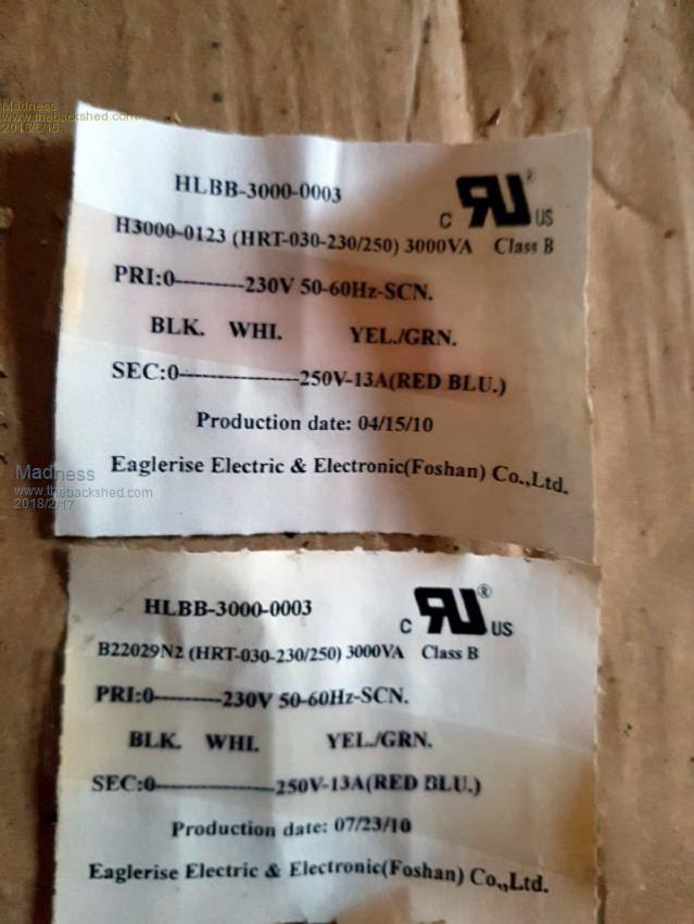
This is one type that I used.  There are only 10 types of people in the world: those who understand binary, and those who don't. |
||||
renewableMark Guru Joined: 09/12/2017 Location: AustraliaPosts: 1678 |
Mine was the same as Mad's one. Cheers Caveman Mark Off grid eastern Melb |
||||
| Warpspeed Guru Joined: 09/08/2007 Location: AustraliaPosts: 4406 |
O/k thanks guys, seeing is believing ! It looks like a rewind job then, which should not be too difficult. It also means that it does not really matter which winding is inside or outside as both will have very nearly the same number of turns anyway. I am planning to use only one core so that should make things easier as well. It still has me stuffed though, how these can possibly work right down to 150v dc input with a 230v primary winding. Cheers, Tony. |
||||
renewableMark Guru Joined: 09/12/2017 Location: AustraliaPosts: 1678 |
I'm having a bugger of a time testing these fets, without a big battery bank the resistors just draw the power and the values constantly change, it never settles. Cheers Caveman Mark Off grid eastern Melb |
||||
renewableMark Guru Joined: 09/12/2017 Location: AustraliaPosts: 1678 |
looking at a value that is dropping I can look at both meters at the same time I got 15mv and .05A=300 Cheers Caveman Mark Off grid eastern Melb |
||||
Madness Guru Joined: 08/10/2011 Location: AustraliaPosts: 2498 |
How many watts are your resistors? Heat will effect them the ones I use are 2 X 10 watt ones off the Areosharp PCB's. A car battery with a charger should give you plenty of power. There are only 10 types of people in the world: those who understand binary, and those who don't. |
||||
renewableMark Guru Joined: 09/12/2017 Location: AustraliaPosts: 1678 |
I was using the two big ones from the aero sharp in parallel. 20ah 48v bank Cheers Caveman Mark Off grid eastern Melb |
||||
Madness Guru Joined: 08/10/2011 Location: AustraliaPosts: 2498 |
You need to make a good connection to the MOSFET I use a 3 way 5 mm spaced pcb screw socket. I put the MOSFET in and push it at right angles to the legs to get some leverage. I get the odd bad reading, then I just lift it and push it down again. The 300 milliohm reading you are getting is the result of a poor connection. There are only 10 types of people in the world: those who understand binary, and those who don't. |
||||
| Warpspeed Guru Joined: 09/08/2007 Location: AustraliaPosts: 4406 |
I really do not like sticking my head up any more in these threads to give advice, it always gets shot off. But those "mosfets" you are testing, recovered from an Aerosharp (?) probably are not mosfets at all, but IGBTs that are an entirely different device to a MOSFET. Look up the data sheet for the specific device. Your testing technique is probably perfect. But RDSon testing is not relevant for IGBTs. Cheers, Tony. |
||||
Madness Guru Joined: 08/10/2011 Location: AustraliaPosts: 2498 |
Sorry don't want to take a shot at you. He is testing HY4008w MOSFETs he has purchased. There are only 10 types of people in the world: those who understand binary, and those who don't. |
||||
renewableMark Guru Joined: 09/12/2017 Location: AustraliaPosts: 1678 |
No one is going to shoot your head off Tony lol Nah I bought them from OS, they are 4008's The "two big ones" I was referring to the resistors which I checked were 33 ohms. Anyway I cracked it and packed up for today I'll look at it again tomorrow. I might get you to give me a hand Tony if you don't mind.  Cheers Caveman Mark Off grid eastern Melb |
||||
| johnmc Senior Member Joined: 21/01/2011 Location: AustraliaPosts: 282 |
Good day all Over heating of the resistor caused non repeatable RDS on results , Dropped the resistor in a tub of water fixed the variable RDS on problem cheers john johnmc |
||||