
|

|
Forum Index : Electronics : 8 KW Inverter Build
| Author | Message | ||||
Grogster Admin Group Joined: 31/12/2012 Location: New ZealandPosts: 9308 |
Okey dokey. How many of those RIFA caps would you use? How much capacitance would you be aiming for if you were building it? Smoke makes things work. When the smoke gets out, it stops! |
||||
| Warpspeed Guru Joined: 09/08/2007 Location: AustraliaPosts: 4406 |
Just one should work fine for the purpose of spike reduction. Going completely off topic, I am not now not planning to build the original 3Kw/6Kw full bridge dc to dc 20Khz converter (30v/60v @ 100amps) to power my inverter from ten (twenty in future) lithium cells. The reason being it would have run fine at full load but behaved very badly at partial or zero load. I built a 750 watt prototype to test with four much smaller mosfets and found it very difficult to control the output voltage at very low power, and the response to step load changes was not as good as I had hoped. That meant every time my refrigerator started up, the lights would flicker badly. I am now building four direct dc to dc direct boost converters each of about 600 watts which draw almost nothing at zero load and has lightning fast response to step load changes. Four of those (interleaved) will give me 2.4Kw with excellent performance. And later if I can afford to upgrade to 60 volts worth of Lithium 4.8Kw. So complete change of plans here. The big H bridge mentioned above will not now be used. I just bought these http://www.ebay.com.au/itm/332104924020?_trksid=p2060353.m2749.l2649&ssPageName=STRK%3AMEBIDX%3AIT which will be for my four boost converters. Cheers, Tony. |
||||
Madness Guru Joined: 08/10/2011 Location: AustraliaPosts: 2498 |
For what is worth Warp the Ozinverter's voltage regulation is very stable regardless of load. Even with my charge controllers using a PWM signal to a SSR that feeds excess power to my hot water. My old trace inverter is not so good and lights flicker etc and my UPS on computers groans and carries on when that is happening but with the Ozinverter doing the same it runs almost silent and voltage only varies by a couple volts. There are only 10 types of people in the world: those who understand binary, and those who don't. |
||||
| Warpspeed Guru Joined: 09/08/2007 Location: AustraliaPosts: 4406 |
Yes I have no doubt about that for an inverter. But a PWM dc to dc converter is a very different thing to an inverter. PWM can only change the averaged output voltage, where you follow that with a rectifier and a filter choke / capacitor filter, the filter output dc will also follow the average but only if it has some minimum load applied. Consider what happens at zero load. The output capacitor will charge right up to the peak voltage, and even if the PWM goes to 0.1%, it still charges to the peak voltage which may be way too high. So at zero load the PWM control system completely loses control of the output. That is not a problem if the load never falls below (say?) 5% or 10% full output. But if its a 5Kw supply, that is 250 or 500 Watts, below which you have little or no output voltage regulation control. That makes forward converters very efficient at very high power, but virtually uncontrollable at zero load. I should have realised this, but it was not until I did some actual testing it all became painfully obvious. So I smacked myself in the head and built a dc to dc boost converter which has much better control characteristics and is more efficient at low power, but is much less efficient at full power. As It will rarely if ever see full maximum power continuously, and then probably only for short bursts its an excellent tradeoff. Cheers, Tony. |
||||
| Tinker Guru Joined: 07/11/2007 Location: AustraliaPosts: 1904 |
May I suggest not to use steel spacers for what is a high current connection. I'm doing the connections in a similar way but with copper spacers (turned from copper rod) but aluminium spacers would also be better than steel. Klaus |
||||
| Warpspeed Guru Joined: 09/08/2007 Location: AustraliaPosts: 4406 |
Yes quite right, I was planning to do something a bit better later on for those spacers. At the time it was only a preliminary mechanical mock up. I have a lathe here so that type of thing is easy, but I lacked any better material at the time. The long 5mm bolt that goes up through the Hall sensor is surrounded by some 3/8 copper pipe that is a nice snug press fit through the hole in the Hall sensor. Its funny though, you see TO220 packaged mosfets with those skinny legs rated to carry 100 amps or more in the data. But people (myself included) look at a 5mm or 6mm steel bolt and wonder how much current it can carry. Cheers, Tony. |
||||
Madness Guru Joined: 08/10/2011 Location: AustraliaPosts: 2498 |
There are lots of copper and brass bolts, washers etc on Ali express for very little money if you are pedantic about the resistance. There are only 10 types of people in the world: those who understand binary, and those who don't. |
||||
oztules Guru Joined: 26/07/2007 Location: AustraliaPosts: 1686 |
Been pondering this for a bit, and had a chance discussion with Gordon ( from here ). He has had a lot to do with this stuff during his time in the solar challenges ( last century) He feels that the inductor we use is simply a choke for the frequency I didn't design it for. It has nothing to do with the fundamental frequency we are switching at, but rather chokes off the excessive currents in the first few nano seconds of the steep rise time of the switching. This is probably more in the order of 100 mhz, not the 20khz we switch. This makes sense to me, as the inductance is so tiny to make such a huge difference.... now I see why. It explains the heat in the inductor as well.... that hf frequency energy has to be dissipated. Thats the first thing. Next... drive problems. He agrees the cross over or near cross over glitches cold be caused from drive or lack thereof. A simple solution may be to use a bigger cap on the 12v supply side of the high side switch driver. It could be that we are drooping on the drive voltage to the chip... so maybe use a 47uf instead of the 10uf.... and a ceramic one or tantalum perhaps. The bypass caps need to be as close as possible to the vcc and gnd of the input side as well. ( mine is already). Failing that then a totem like Madness is doing will probably solve it. ...........oztules Village idiot...or... just another hack out of his depth |
||||
Madness Guru Joined: 08/10/2011 Location: AustraliaPosts: 2498 |
Hi Oz, I tried changing the Zener diode to 18 volts on the supply to the IR2110 chips, it made no difference to the wave however with the board just idling while I went over it with the CRO it got very hot. I went to put a clip on the output and nearly burnt my finger, it was up to 85 degrees with no load. It was drawing 4 amps with zero load. I have gone over the PCB I am using ATM and resoldered everything then I back tracked on what I have done and remembered how I got a better result with no choke. I tried that again this morning with a standard EGS002 control board with 4u7 removed and a full house of HY4008's, no choke and the waveform is perfect. Put the Ecore choke in and it has wobbles and blips, it improves with load but still looks like previous results in the image below, however this is with the default EGS002 dead time, the image is from a different Power PCB and maximum dead time. 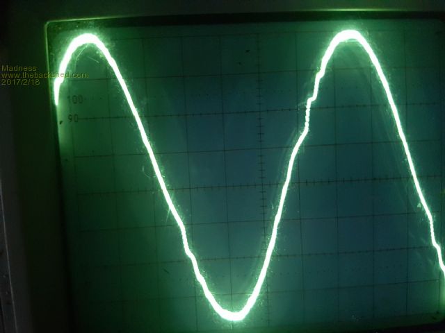 Have you got more details Oz of the choke you mentioned in the post quoted above that worked so well? There are only 10 types of people in the world: those who understand binary, and those who don't. |
||||
Madness Guru Joined: 08/10/2011 Location: AustraliaPosts: 2498 |
Just been trying a few things with the Inverter, setup is eg8010 board with 4.7uf Monolithic caps added to the 10uf electrolytic on the 12V side of the IR2110, single core Toroid and no load. 1 turn through Ferrite Ring 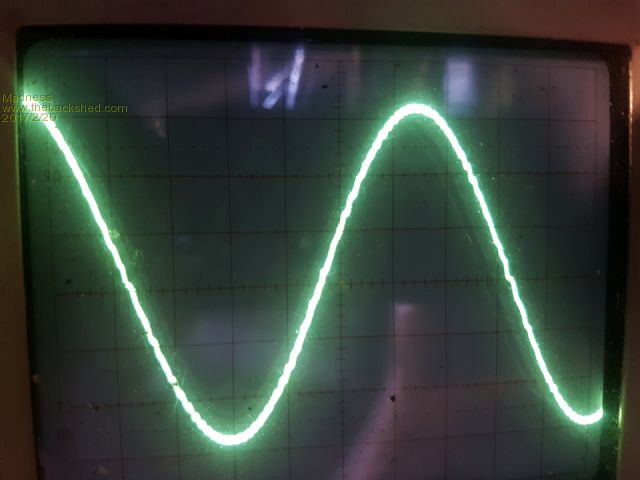 2 turns through Ferrite Ring 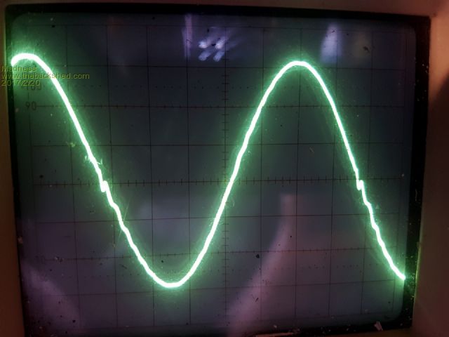 3 turns through Ferrite Ring 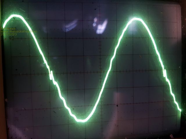 4 turns through Ferrite Ring 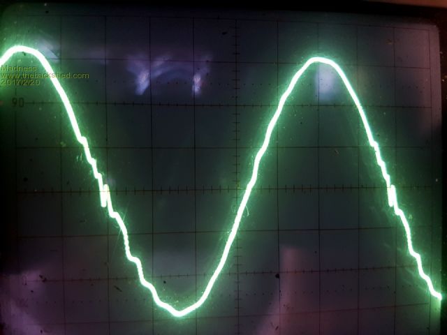 5 turns through Ferrite Ring 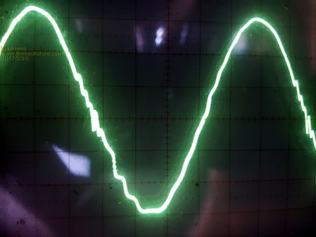 3 turns through E-Core 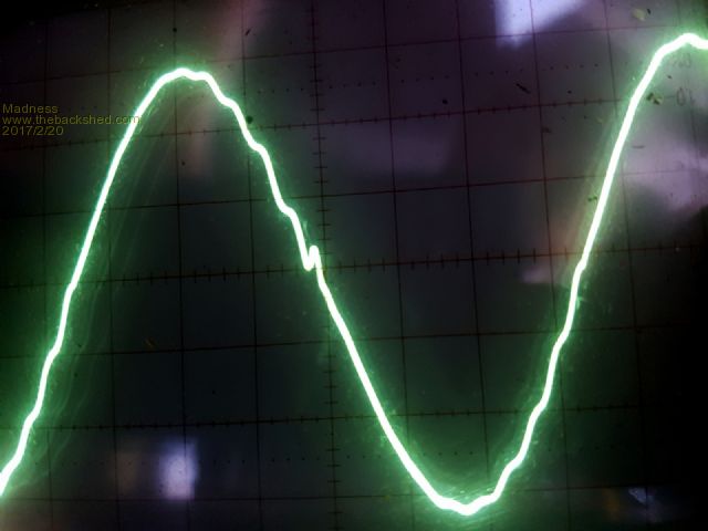 There are only 10 types of people in the world: those who understand binary, and those who don't. |
||||
| Tinker Guru Joined: 07/11/2007 Location: AustraliaPosts: 1904 |
Yes but, also measure the no load current. The whole idea of the E-core or ferrite ring was to reduce this idling current. Remember, this current draw happens 24/7. So, unless your battery bank can afford to just laugh at this idling current... Somewhere its going to be a compromise I guess, juggling the lowest idling current with an acceptable sine wave. Klaus |
||||
Madness Guru Joined: 08/10/2011 Location: AustraliaPosts: 2498 |
Until I get the waveform correct I am going to keep blowing MOSFETs, there is no compromise on this. I did measure current while doing this and with one turn it was 2A at best just a touch over 1A. With the single turn and no load there was noticeable heating in the Ferrite ring. Something is amiss I just realised those images are upside down so should be like this. 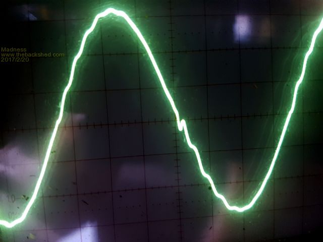 I will try a different MOSFET board later and see if there is any change as a result of that. There are only 10 types of people in the world: those who understand binary, and those who don't. |
||||
oztules Guru Joined: 26/07/2007 Location: AustraliaPosts: 1686 |
Saw the unit running at 6kw or more, so thought a few pics... over 6kw driving hot water, front loader, electric jug freezers, tv, etc etc. Interesting wave form showing a glitch... blown up as big as I can make it... and it turns out that the glitch was caused by the phase triggering of the front load washing machine motor... each time it rotated slowly for the wash, it got the glitch, then a few second later... would stop, and reverse direction.... whilst stopped, it looks like this.... ( still pulling near 6kw with motor stopped ) So now we know that phase triggered appliances using fair power, will distort the wave form... but not too much... especially when pulling 6kw or more. I do like these 8010 things. This one has done half a mega watt, but was only idling for a week or so while I was testing another. The original power jack unit in the hydro box was a few years old, and gave up while only doing a few watts a couple of days ago..... I think it was to do with sensitive under side of the board stuff.... It would not switch on if left for a few days over here ( very humid island at night ), and would need a hair dryer to start it up... should never have turned that one off for extended periods whilst testing other units in it's place. Have heard of other powr jacks doing the same thing if youleave the tape they stuck on the back ( i did). ........oztules Edit.... went and had another look after some of the loads went away, and the wave looks identical to the bottom one at 2.2kw, 3.5kw, 4.5kw, and 6.1kw. It was only the phase triggering of the triac control in the washer that made any difference at all. Voltage remained within a volt at all times. ( I run around the 233v mark) Village idiot...or... just another hack out of his depth |
||||
Madness Guru Joined: 08/10/2011 Location: AustraliaPosts: 2498 |
I received some 4110 FETs from the same supplier that OZtules has used, with 8 of these only on the PCB I get textbook perfect sinewave. This is with a load up to 1200W and idle power is under 15W with a single core Toroid. So I have to conclude that the problem is not related to the magnetics, as spikes appear at idle and at 1200W load I have got wider waves especially at the peak. Tomorrow I will add more FETs, 4 at time and test to see how it goes. There are only 10 types of people in the world: those who understand binary, and those who don't. |
||||
Madness Guru Joined: 08/10/2011 Location: AustraliaPosts: 2498 |
Here is another modification I am planning to try. I have some 1N5819 Diodes that should be fine for this, here is a description of it. Driver protection Another must-do with direct drive and with gate drive ICs using bipolar output stage is to provide suitable protection for the output bipolar transistors against reverse currents. As indicated in the simplified diagram in Figure 9, the output stage of the integrated bipolar drivers is built from npn transistors due to their more efficient area utilization and better performance. 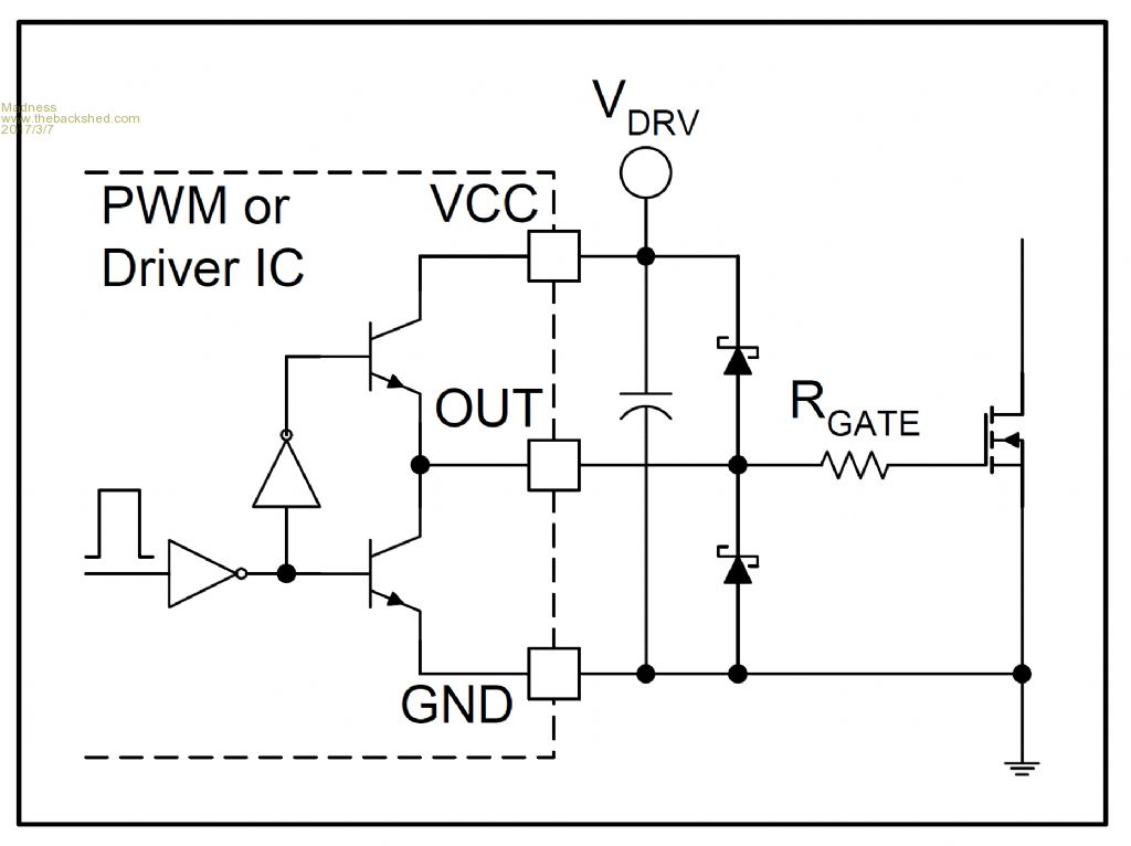 The npn transistors can handle currents in one direction only. The high side npn can source but can not sink current while the low side is exactly the opposite. Unavoidable oscillations between the source inductor and the input capacitor of the MOSFET during turn-on and turn-off necessitate that current should be able to flow in both directions at the output of the driver. To provide a path for reverse currents, low forward voltage drop Schottky diodes are generally needed to protect the outputs. The diodes must be placed very close to the output pin and to the bypass capacitor of the driver. It is important to point out also, that the diodes protect the driver only, they are not clamping the gate-to-source voltage against excessive ringing especially with direct drive where the control IC might be far away from the gate-source terminals of the MOSFET. There are only 10 types of people in the world: those who understand binary, and those who don't. |
||||
| Warpspeed Guru Joined: 09/08/2007 Location: AustraliaPosts: 4406 |
This is definitely true of bipolar transistor gate drivers as often found in many of the bipolar technology PWM control chips. However, most of the dedicated high current gate drivers such as TC4452 are CMOS devices and use P and N channel mosfets in the output. Mosfets have internal source drain diodes as part of the normal internal mosfet structure. Any serious ringing will be clamped by the internal diodes and external shottky protection diodes offer no advantage and are not needed. Cheers, Tony. |
||||
Madness Guru Joined: 08/10/2011 Location: AustraliaPosts: 2498 |
I guess that would apply to the IR2110's as well. There are only 10 types of people in the world: those who understand binary, and those who don't. |
||||
| Warpspeed Guru Joined: 09/08/2007 Location: AustraliaPosts: 4406 |
IR2110's are mos technology and don't need output protection diodes. http://pdf1.alldatasheet.com/datasheet-pdf/view/82793/IRF/IR2110.html Usually the first page of any data sheet will tell you if the chip uses bipolar or mos technology, and the application notes will usually include some circuit examples of good practice. Any special requirements such as output protection diodes will be shown or not there as appropriate. Here is the data sheet of a fast (1.5 Mhz) PWM control chip that uses bipolar transistors and has a totem pole output. The example circuit shows the protective Shottky diodes on the gate driver outputs. http://www.ti.com/lit/ds/symlink/uc2825.pdf Cheers, Tony. |
||||
Madness Guru Joined: 08/10/2011 Location: AustraliaPosts: 2498 |
Thanks Warp, No Diodes on the IR2110 example circuits and they are MOSFETs, I have learnt something :) There are only 10 types of people in the world: those who understand binary, and those who don't. |
||||
Madness Guru Joined: 08/10/2011 Location: AustraliaPosts: 2498 |
If anybody is interested you can buy HY4008W MOSFETs HERE for $1.37 X 100. There are smaller quantities available, I asked if they were any cheaper the 100 and they created this listing. I have bought from this supplier before and they all tested within 0.1 milliohms of 2.7 milliohms RDS ON. There are only 10 types of people in the world: those who understand binary, and those who don't. |
||||