
|

|
Forum Index : Electronics : A newbie ozinverter build
| Author | Message | ||||
| Tinker Guru Joined: 07/11/2007 Location: AustraliaPosts: 1904 |
Your choke might need re visiting but the rest of your test figures look good. I just did an efficiency test with a similar load on my 6KW inverter and came up with the same result: 91.7% at a 2040W load. At 4000W that dropped to 89% efficient. The choke in my inverter hums slightly with 2KW and louder with 4KW. I have not noticed it getting hot but now with the thing being fully enclosed I don't know, doubt it though. I would not worry about soft epoxy until you are well past 60 degree C. I set my fans to come on at 39 degrees C on the large heat sink. Klaus |
||||
| tinyt Guru Joined: 12/11/2017 Location: United StatesPosts: 438 |
AT the start, heatsink temp was 24.5C(ambient), there is no fan as the box is not yet complete. This picture is an earlier setup outside the house. The stove heating element is contributing to the temperature rise and also heating up the top of my power supply. So in my latest testing, I moved the stove heating element about 2 feet away. 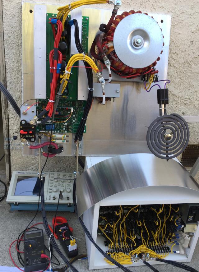 |
||||
| tinyt Guru Joined: 12/11/2017 Location: United StatesPosts: 438 |
For measuring choke winding temperature, I just inserted the thermocouple probe in the gap between the core outer leg and winding. It measured 83 deg.C. I think I need to increase the wire cross-section. But I need to get an adequate core. |
||||
| tinyt Guru Joined: 12/11/2017 Location: United StatesPosts: 438 |
I decided that for now I will still use the same EI core for the choke and changed the winding from: AWG 12, 6 strands, 19.5 turns. Effective copper wire cross section = 19.8 mm sq. to: AWG 14, 15 strands, 7.5 turns. Effective copper wire cross section = 31.2 mm sq. It should lower winding temperature rise. But I don't know the effect of lower inductance. The 19.5 turns measured 220 uH. The 7.5 turns measures 50 uH. Connected it and the no load waveform is still good. But the no load DC current draw went up from 0.31A to 0.57A. Looks like I need a bigger EI core to get higher inductance with the larger wire cross section. |
||||
renewableMark Guru Joined: 09/12/2017 Location: AustraliaPosts: 1678 |
Why don't you just add another and put them in series? I did that and it works a treat, mine has a big iron core and a double stack E70 (4 halves), Looks like you have plenty of room for it. Cheers Caveman Mark Off grid eastern Melb |
||||
| Tinker Guru Joined: 07/11/2007 Location: AustraliaPosts: 1904 |
Don't forget that we initially built these inverters using a E65 ferrite core choke that had just 3 or 4 windings of as big wire that could be fitted. The best of the three I made measured 54uH with 4.5 turns of 63mm sq of rectangular enameled wire. The thing worked fine, no air gap on mine bar the Klapton tape film on each core mating surface to stop it squeal under load. Of course, that choke did saturate and the overall efficiency was a bit higher than now with my much bigger non saturating silicon steel core choke with a 2mm air gap. It comes down to wanting to build just a working inverter or one that performs better than anybody else's home built inverter     . .Klaus |
||||
| tinyt Guru Joined: 12/11/2017 Location: United StatesPosts: 438 |
Mark, Klaus, I am going to follow your advice and connect a ferrite choke in series with the EI choke. I wanted to get back the 0.31A idle current because I can only afford to get four 12v 100AH batteries, so low idle power is important for me. By the way that empty space below the toroid is for the solar charge controller and solar current sensors. |
||||
| tinyt Guru Joined: 12/11/2017 Location: United StatesPosts: 438 |
I don't have an Exx ferrite core but I have several small ferrite rings. With 5 turns, the inductance measured 137 uH. But when I cut the gap, it went down to 4 uH. The gaps in the picture were cut with a thin blade diamond saw. They will be filled with epoxy for mechanical strength. 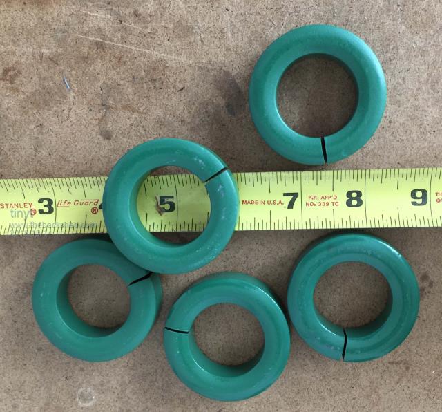 I glued the gapped five rings together and used the 84 wire strands left-over from the toroid primary for the winding of this ring stack. 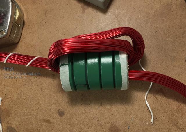 Here it is, 5 turns made it. They are not epoxied yet but will test as is. Inductance measured at 70 uH. 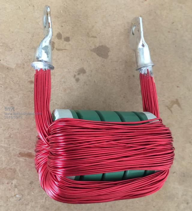 Will connect it in series with the EI choke and do load soak test later. |
||||
renewableMark Guru Joined: 09/12/2017 Location: AustraliaPosts: 1678 |
Give it a go, but you may find it's a bit small. The big iron core used in my one saturates around 145A and as well as that 4 halves of these got used in series 2 sets got clamped side by side. Cheers Caveman Mark Off grid eastern Melb |
||||
| tinyt Guru Joined: 12/11/2017 Location: United StatesPosts: 438 |
I envy you guys, I don't have a giant toroid, massive battery banks, and huge solar arrays to power the entire house like you guys.  I started this project just to remove from the grid a 1.5hp pool pump. If I can remove more, I will be happy. (For now.  ) ) |
||||
| tinyt Guru Joined: 12/11/2017 Location: United StatesPosts: 438 |
With the EI core and ferrite ring chokes in series, I am back to idling dc current of 0.31A. Waveshape looks good to me.(scope trigger is stopped in this pic.) 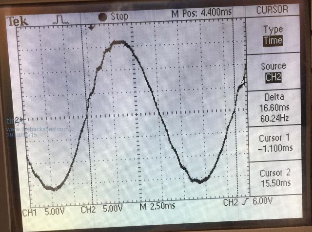 I trimmed the VFB pot for a lower output of ~224vac as it was a little bit high for me (236vac). Here is my load soak test setup, 4kw load shown, ring choke not yet securely mounted. Ambient temperature was about 23 deg. C. 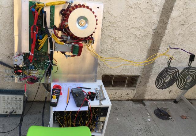 Here is waveshape with 1.2 kw stove heating element. (scope trigger is stopped in this pic.) 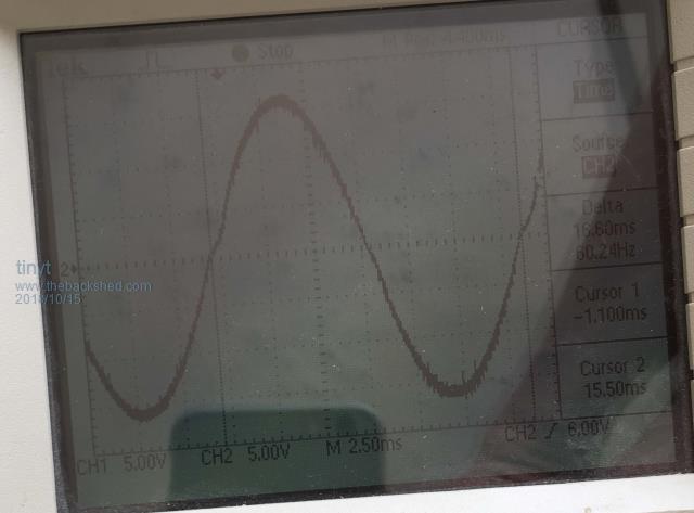 Here are some numbers for the 1.2kw load. 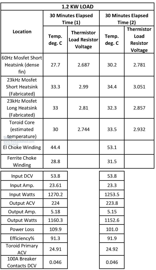 Then I changed the load to 2kw. Here is waveshape with 2 kw stove heating element. (scope trigger is stopped in this pic.) 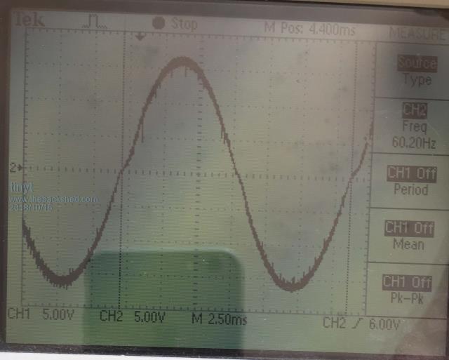 Here are some numbers for 2 kw load. 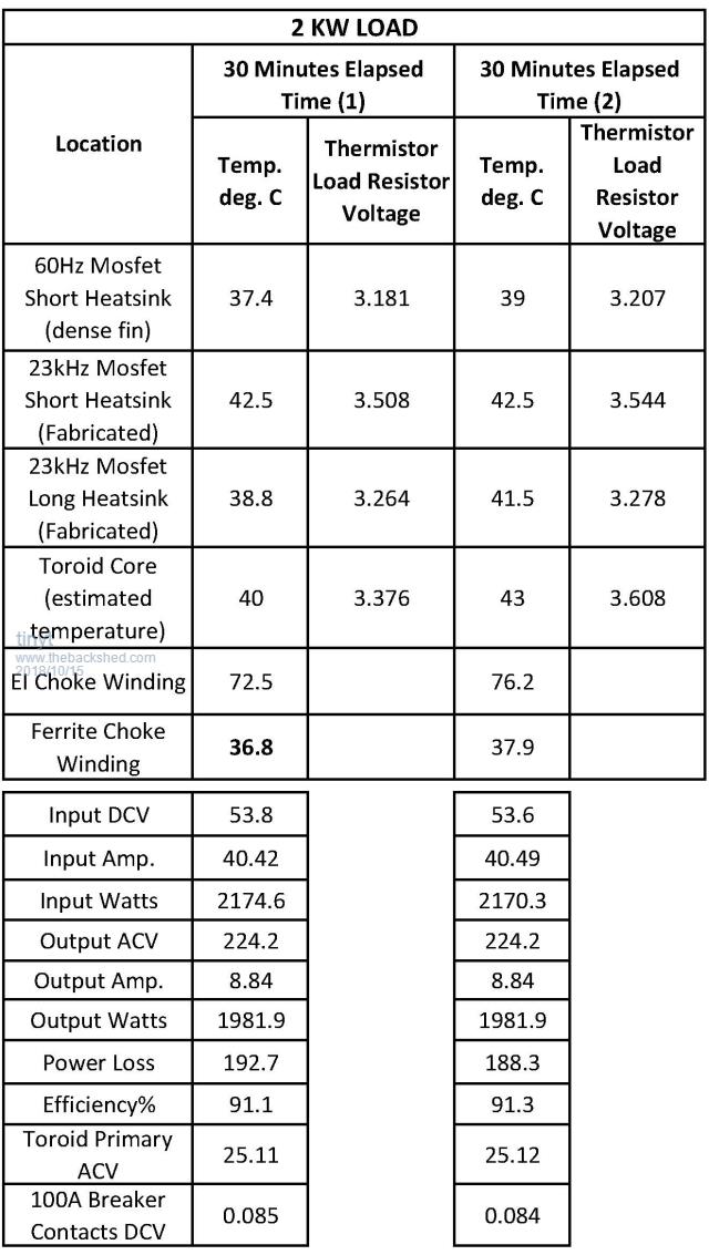 Then I changed the load to 3.2kw (1.2kw in parallel with 2kw). Here is waveshape with 3.2 kw stove heating elements. (scope trigger is running in this pic.) 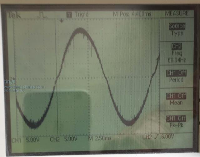 After about 30 seconds, the 100A breaker tripped. prior to tripping I read the voltage drop across the breaker contacts to be 0.116vdc. It should not trip at 65.4A, maybe defective. So I replaced the breaker with a higher rating. Here are some numbers for 3.2 kw load. 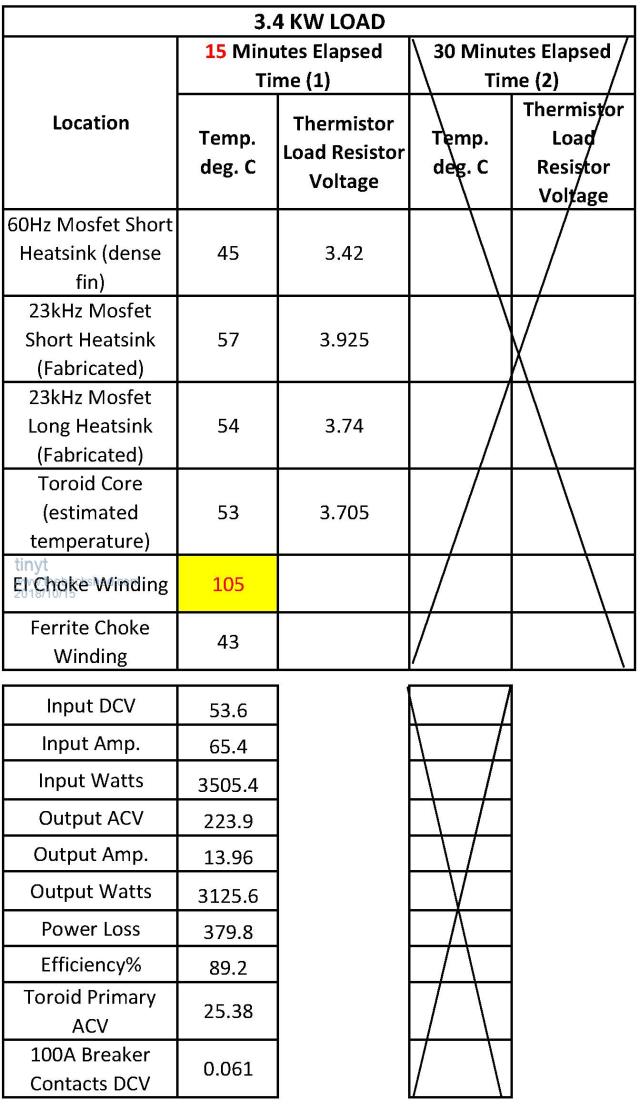 I was able to soak for only 15 minutes since the EI choke winding temperature became too high. Note that there is no force air cooling in this test. I let the assembly cool down using a fan. Then I connected two 2kw stove heating elements. Quickly took waveform picture, it is basically the same as the those from lower loads. See below (scope trigger is running in this pic.): 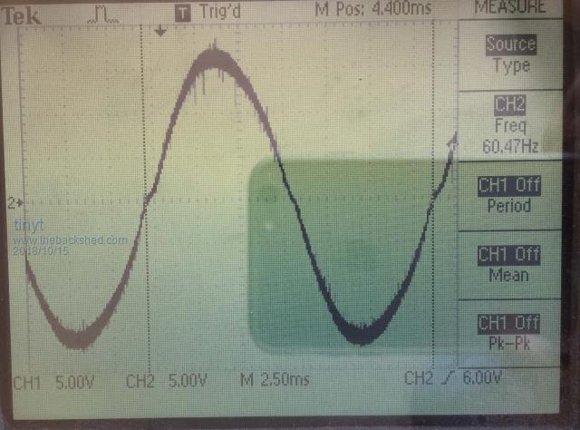 After about 10 seconds, it keeps shutting down with VFB under voltage indication (LED flash 4x) I was able to take the following values before the shutdown. DC power input: 53.2 x 85 = 4522 watts AC power output: 224 x 18.1 = 4054.4 watts Toroid primary ACV: 25.58vac Power loss: 4552 - 4054.4 = 467.6 watts Efficiency: 100(4054.4/4522) = 89.6% If I use a better EI choke I think the numbers will improve, but right now am happy with the results. At power levels that match my toroid size, I think the fabricated heatsink is adequate specially with forced air cooling. I think I am done with characterizing the power section. Since the EGS002 already has anti cross-conduction transistors installed for shoot-through prevention, I prefer to use it right now. But I still will not use its TFB and IFB inputs. I will be using the on board arduino nano for fan control and SPWMEN on/off. |
||||
| noneyabussiness Guru Joined: 31/07/2017 Location: AustraliaPosts: 513 |
Something to be proud of. .. and interesting numbers. .. thanks Tiny I think it works !! |
||||
| Tinker Guru Joined: 07/11/2007 Location: AustraliaPosts: 1904 |
I'll second that  . .I do have a suspicion tinyt has by now been infected by the inverter building bug... I've got it bad,, I'm thinking of building #5  . .Klaus |
||||
renewableMark Guru Joined: 09/12/2017 Location: AustraliaPosts: 1678 |
Big loads need a fan mate, even a big heatsink would need them, looks good and no flames yet  A bit odd to see your chokes heating up so much, mine barely get warm. If you plan to run them on light duties they may be just fine though. Cheers Caveman Mark Off grid eastern Melb |
||||
| tinyt Guru Joined: 12/11/2017 Location: United StatesPosts: 438 |
Still trying to improve the only EI choke I have. Based on my readings about skin effect on copper wires, AWG #19 will have an AC resistance equal to its DC resistance at 21kHz for 100% skin depth. The radius of awg #19 is .0359/2 = .01795 inch. I assume this will be the 100% skin depth value and I will assume it to be the same for 23kHz. Doing some rough calculations on the wires I earlier used, the AWG #14 (.0641 inch dia.) will have only 80% of its cross-section effective for 23kHz current flow and the AWG #12 (.0808 inch dia.) will have only 69% of its cross-section effective for 23kHz current flow. So at 23kHz the effective copper wire cross sections will be: AWG 12, 6 strands, 19.5 turns. Effective copper wire cross section = (19.8 mm sq.) x .8 = 15.84 mm sq. AWG 14, 15 strands, 7.5 turns. Effective copper wire cross section = (31.2 mm sq.) x .69 = 21.53 mm sq. Now I used AWG #19 and was able to squeeze in the winding window 65 strands, 8 turns. Effective copper wire cross section = (.0658 inch sq. or 42.45 mm sq.) x 1 = 42.45 mm sq. - Much larger than the earlier two. Picture is still a work in progress, will test when completed and find out. 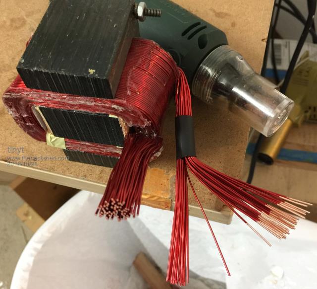 |
||||
| tinyt Guru Joined: 12/11/2017 Location: United StatesPosts: 438 |
This is a long post. So I started temperature soak testing with the new EI choke. Using a single thermocouple to measure at different locations is tedious, so I used the pre-installed NTC thermistors and wrote code for the nano to do it. The code reports readings every minute. The RS-232 packet is comma separated text for import to excel if desired. Col 1 = Minute count Col 2 = Temperature for 23kHz Mosfet Short Heatsink (Fabricated) Col 3 = Temperature for 60Hz Mosfet Short Heatsink (purchased dense fin) Col 4 = Temperature for 23kHz Mosfet Long Heatsink (Fabricated) Col 5 = Temperature for Power Toroid Col 6 = Temperature for EI Choke Col 7 = Fan OFF/ON indicator 0 = OFF, 1 = ON Col 8 = Raw and noisy 10-bit ADC value for battery voltage (trimpot set to 4V when Battery is 54V) Here is the packet for my 2.2kw load testing: 1, 18, 17, 18, 18, 18,0,813 2, 20, 18, 21, 19, 18,0,808 3, 22, 19, 22, 20, 18,0,814 4, 23, 19, 23, 20, 19,0,808 5, 24, 20, 24, 21, 19,0,812 6, 26, 20, 25, 22, 19,0,811 7, 27, 21, 26, 22, 19,0,809 8, 28, 21, 27, 23, 20,0,813 9, 29, 22, 28, 24, 20,0,814 10, 30, 22, 29, 25, 20,0,809 11, 30, 22, 29, 25, 20,0,815 12, 31, 23, 30, 26, 21,0,813 13, 31, 23, 30, 27, 21,0,812 14, 32, 23, 31, 27, 21,0,810 15, 32, 24, 31, 28, 21,0,815 16, 33, 24, 32, 28, 22,0,814 17, 33, 24, 32, 29, 22,0,814 18, 34, 25, 32, 29, 22,0,810 19, 35, 25, 33, 30, 22,0,810 20, 35, 26, 33, 30, 22,0,813 21, 35, 26, 33, 31, 23,0,816 22, 36, 26, 33, 31, 23,0,814 23, 36, 26, 33, 32, 23,0,810 24, 37, 27, 33, 32, 23,0,811 25, 37, 27, 33, 33, 23,0,814 26, 37, 27, 33, 33, 24,0,816 27, 37, 27, 33, 34, 24,0,813 28, 38, 28, 34, 34, 24,0,814 29, 38, 28, 34, 35, 24,0,810 30, 38, 28, 34, 35, 25,0,810 31, 38, 28, 35, 35, 25,0,814 32, 38, 29, 35, 36, 25,0,816 33, 38, 29, 35, 36, 26,0,814 34, 38, 29, 36, 37, 26,0,811 35, 39, 29, 36, 37, 26,0,811 36, 39, 29, 36, 37, 26,0,813 37, 40, 30, 36, 38, 27,0,814 38, 40, 30, 36, 39, 27,0,816 39, 40, 30, 37, 39, 27,0,815 40, 40, 31, 37, 40, 27,0,813 41, 40, 31, 37, 40, 27,0,814 42, 40, 31, 37, 41, 28,0,810 43, 40, 31, 37, 41, 28,0,811 44, 41, 32, 37, 41, 28,0,814 45, 41, 32, 37, 42, 28,0,816 46, 41, 32, 37, 42, 29,0,816 47, 41, 32, 38, 42, 29,0,815 48, 41, 33, 38, 42, 29,0,812 49, 41, 33, 38, 43, 29,0,810 50, 41, 33, 37, 42, 29,0,810 51, 41, 33, 37, 42, 30,0,814 52, 41, 32, 37, 42, 30,0,815 53, 41, 32, 36, 42, 30,0,816 54, 41, 32, 36, 43, 30,0,814 55, 42, 33, 37, 44, 30,0,811 56, 42, 33, 37, 44, 30,0,810 57, 42, 33, 37, 44, 31,0,812 58, 42, 33, 37, 44, 31,0,815 59, 42, 33, 37, 45, 31,0,816 60, 42, 33, 38, 45, 31,0,814 61, 42, 34, 38, 45, 31,0,812 62, 42, 34, 38, 45, 32,0,810 63, 42, 34, 38, 45, 32,0,811 Here is a summary of my interrupted testing: 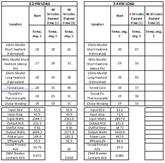 Note that for the 2.2kw load, the efficiency dropped by about 1.6% after 1 hour. Note also that the toroid core has the highest temperature reading after 1 hour. Then I cooled the unit a little bit and changed to 3.4kw load. After about 11 minutes the CB tripped. When I reset the CB and re-started the inverter, the EGS002 LED now reports under-voltage. I cooled down the unit again and re-started while monitoring the CB contact DCV, it went up from .085v to .12v prior to tripping again after about 7 minutes. Here is the interrupted packet: 1, 36, 29, 35, 30, 29,0,812 2, 39, 31, 38, 31, 30,0,812 3, 42, 32, 40, 33, 30,0,814 4, 44, 33, 42, 34, 31,0,814 5, 45, 34, 43, 35, 31,0,814 6, 47, 35, 45, 37, 32,0,806 When I was measuring the CB contact DCV, I also felt that one side of the CB felt warmer than the other sides, has be a thermal type breaker, so I thought it is the CB. I disconnected the toroid from the mosfet bridge and load and applied 230vac at its output winding, the current draw measured 0.11A. I let the toroid cool down so that its core temperature is the same as ambient and re-measured. The current draw went down to its original 0.055A as shown on page 10 of this thread. On page 10 of this thread I showed that I did not remove the original 230V winding but located the center of the winding and split it equally into two separate 115v and used them. I also mentioned that this original winding is a split return type and in my picture it showed no insulation separating the two that are split. I should have completely removed this winding and wound a new one. I think the reason this toroid was removed from equipment and sold in ebay is it is drawing excessive current when it gets hot. At that time the seller had more than 6 of these so I think that batch has a design defect and what I bought was experiencing partial short at high temperature. Maybe the others that were being sold were completely shorted. So after this hard and expensive lesson learned, I now will have to destroy my beautiful creation, salvage just the core and start anew.  |
||||
| wiseguy Guru Joined: 21/06/2018 Location: AustraliaPosts: 1156 |
There are a few things to consider before destroying your creation. Perhaps find another 2 cores and wind another transformer from scratch. Then compare the heating of the second core against the first in the same setup. There would be nothing worse than re-winding anew onto the same cores and then finding that they behave essentially the same. I think the partial short you are suggesting is not really the problem, especially as you experienced efficiencies ~ 90% which is quite respectable. There is a degree of the 25kHz signal that is being "filtered by the core". The series choke also effects the degree of 25kHz that is applied to the Toroid core. I am sure eddy current and the HF magnetizing bias losses are helping the core to heat up. Another checking method could be to run ~230VAC into the secondary, pull a few kW from the primary and check the temperature rise of the transformer running those power levels at a genuine 60 Hz excitation. The core temperature you experienced, whilst a tad high, I dont think its alarmingly high. The idling current increase at the higher temperature is curious but my gut feel is that it is more to do with changes in behaviour of the steel of the core and perhaps the higher temperature increases the eddy current losses ? It seems that since your earlier tests where the choke got damn hot but the toroid appeared to run relatively cool you now have a relatively cool choke and hot toroid, maybe there is a better compromise to be had between these two situations ? If at first you dont succeed, I suggest you avoid sky diving.... Cheers Mike |
||||
| tinyt Guru Joined: 12/11/2017 Location: United StatesPosts: 438 |
Thanks wiseguy for your input. Actually last night, I did the 60Hz excitation on half of the secondary @ 115vac (our regular house outlet voltage) The load on the other half of the secondary is around 1kw and after about 1 hour, the NTC thermistor dropped from about 10k ohms to 5k ohms. Using the formula in https://www.thermistor.com/calculators gives me a core temp of about 41 deg. C. I did not see a jump in current draw. Was not able to measure idle current as it was late at night already. Maybe my earlier idle current draw of 0.11A was a mistake. So maybe it is something else, but I still need to know why the Inverter CB tripped and why the EGS002 indicates undervoltage during that testing. But I will set up for a higher load and do more testing of the toroid alone. So as not to trip the 115vac house outlet circuit breaker I will configure the secondary as an auto-transformer and connect it to the AirCon 230vac line. Have to make up some heavier 115vac loads. Have to think also of an excuse to tell my wife why the electric bill jumped.  |
||||
| gaspo Regular Member Joined: 25/06/2018 Location: AustraliaPosts: 65 |
Tinyt, is that DF-6 wire stripper on that picture? How does it perform, what's the min/max diameter it can strip? I'm thinking of getting one too. |
||||
| tinyt Guru Joined: 12/11/2017 Location: United StatesPosts: 438 |
Hi gaspo, Yes it is the DF-6. I have lost the instruction/spec. But I tried it on AWG 26 (0.4 mm dia) and AWG 9 (2.9 mm dia) and it works. On the 0.4 mm, I had to make sure that the wire that goes inside the cutter is straight, otherwise it will get tangled in the cutter and break. With care you can probably strip smaller diameter wires. The wire guide hole is 4.3 mm dia, so I assume that will be the maximum diameter. But the cutter opens bigger than that. Once you dialed the right speed for the wire diameter and learned the technique of pulling during stripping it works very well. What I bought stops after about 150 operations and I have to let the inside cool down for a bit before continuing. There is probably some sort of thermal protection on the speed control circuit. |
||||