
|

|
Forum Index : Electronics : 8 KW Inverter Build
| Author | Message | ||||
Madness Guru Joined: 08/10/2011 Location: AustraliaPosts: 2498 |
Hi Oz, What effect did the increased dead time have on your waveform? I know mine is still not quite right yet but it is taking everything I have thrown at it and more. I had 2 AC's on today and the oven with it putting out 6.5KW plus for at least 1.5 hours. The second AC is keeping the Inverter cooler, I have no need to run it any harder than that ATM. What I am really loving is the peace of mind being able to work it hard and if it $hit$ itself it is no big deal, the Toroid is protected from overheating by the EG8010 and the power board runs cooler than it but if it fails it easy and cheap to fix. Also I have a backup Inverter that can be switched on in a second if that happened. Heat from the MOSFETs is easy to manage with the 400mm long heat sinks, the Toroid runs warmer. When I get this working correctly I plan to make another 6 in hand 1.6 mm diameter for the secondary and for the as many 2mm wires as I can fit. That will be a little way off though, first I need to get this one right, all going to plan (which it probably won't) I will get the gate driver boards made this Wednesday. In theory we could go much harder with the HY4008's, the PCB I am running ATM has TO247 4110's. The 4 big FET method would be great for those that have slightly more modest power requirements. There are only 10 types of people in the world: those who understand binary, and those who don't. |
||||
oztules Guru Joined: 26/07/2007 Location: AustraliaPosts: 1686 |
The wave looked all wrong... so I stopped and returned to normal. Hell you drive them hard. ..........oztules Village idiot...or... just another hack out of his depth |
||||
Madness Guru Joined: 08/10/2011 Location: AustraliaPosts: 2498 |
Not driving it at all ATM, it stopped last night. Just running at 7-800 watts and had not been working it hard for a few days as the weather cooled down a little, I have not had a chance to do a post mortem yet. So the old Trace is back in action for now. Just about got the Totem Pole drivers ready to test There are only 10 types of people in the world: those who understand binary, and those who don't. |
||||
Grogster Admin Group Joined: 31/12/2012 Location: New ZealandPosts: 9308 |
Well, the IXTN320N10T is no longer available from that Verical link that Warpspeed posted, so I will have to buy the IXFN360N10T instead. The only problem with this, is that you have to buy a minimum of 10 @ $16 a pop. I am not that bothered by that, really. The 360 seems to be a better device looking at the data compared to the 320. What I WOULD like to know though, is what Warpspeed thinks of this part as a replacement for the original one he linked to. Here is a GIF comparison from the IXYS website, of the two devices: 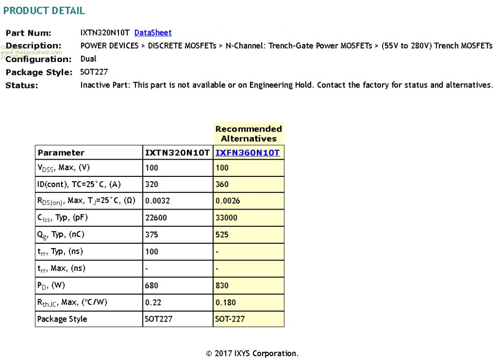 From what I can see, the 360 is actually a better device then the 320, so I should be perfectly fine with this one instead, yes? I am just wanting to check that I am not somehow getting the figures wrong or missing something obvious before I buy these devices. The 360 has a 360-Amp chip capability, but the connecting lugs themselves cannot pass more then 200-Amps continuously. The 360 device can handle surge currents up to 900-Amps, 100v S-D voltage, 20v G-D voltage. Avalanche and military rated. Seems like a bloody strong device to me!  Smoke makes things work. When the smoke gets out, it stops! |
||||
| Tinker Guru Joined: 07/11/2007 Location: AustraliaPosts: 1904 |
Grogster, I ordered 4 off IXTN320s on the 1st of February. They are on their way and I should get them next Friday. So it looks I bought the last of the stock as when checking several suppliers just now, none were available. I better make sure I don't blow them up then.  Too bad that you have to order 10 of the IXTN360's, that gets a bit expensive when the shipping cost is included. edit: I just did some googling and found this:IXT chip This looks cheap and can buy single pieces. But I did not go further into the ordering process. Klaus |
||||
Grogster Admin Group Joined: 31/12/2012 Location: New ZealandPosts: 9308 |
Thanks for that link, Tinker, I will investigate that avenue a little closer, as they are much cheaper. Are they authentic though, that is the question..... I have finished my initial draft of the PCB for these big beefy MOSFET's: 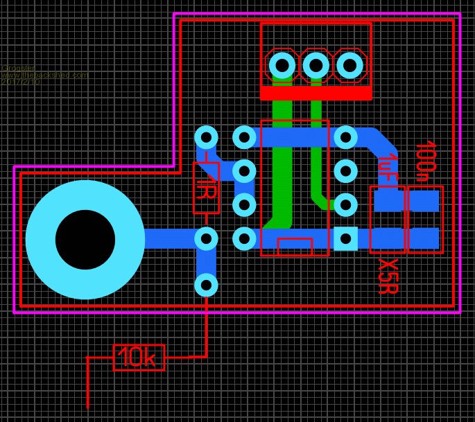 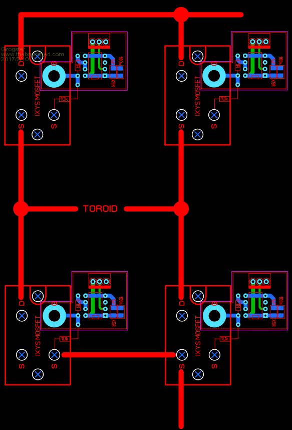 The small PCB bolts DIRECTLY to the gate terminal on the big MOSFET, and keeps the 4452 within about 5mm of the gate itself. The thick red lines in the bottom image, show the heavy current paths, which would be done using 3mm copper bar that I was going to use in an earlier concept. Just drill holes in the right place, and bolt it all together tightly. EDIT: PCB does not show connection to GND(pins 4 and 5 on the DIL chip) - to be completed..... Smoke makes things work. When the smoke gets out, it stops! |
||||
Madness Guru Joined: 08/10/2011 Location: AustraliaPosts: 2498 |
@Grogster, you might want to consider adding snubbers as well to save those MOSFETs from high voltage spikes from the Toroid, or is there protection built into those big FETs? Also you will need a charge pump to trigger the high side MOSFETs. There are only 10 types of people in the world: those who understand binary, and those who don't. |
||||
Grogster Admin Group Joined: 31/12/2012 Location: New ZealandPosts: 9308 |
No snubbers needed with those big MOSFETS when coupled to drivers such as the 4452 as I understand it - Warpspeed said to leave those diodes off the gates. Diode in the big MOSFET is good for 1400-Amps of spike, so... Charge pump is on the mainboard along with the 2110 driver IC's: 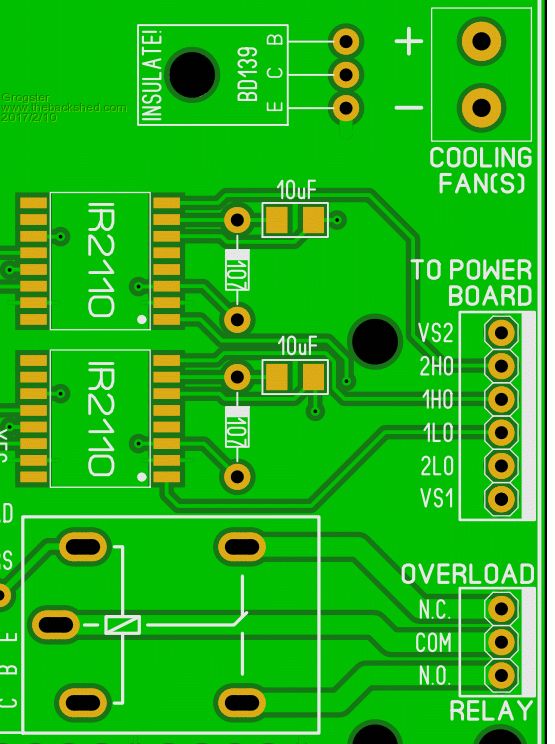 Do you think these should be moved from the 2110 side of the link, to the 4452 gate-driver boards? Warpspeed - what are your thoughts? Smoke makes things work. When the smoke gets out, it stops! |
||||
| Warpspeed Guru Joined: 09/08/2007 Location: AustraliaPosts: 4406 |
If you already have the dual IR2110 driver board, or can buy it cheap Chinese, might as well use it as it is, and extend the three outputs to each of the the four 4452 boards. The gate driver boards also need to include one of the two source connection screws of the big mosfets, so I would extend the circuit board to include both the gate and source screws. A big solid copper ground area would be good too to tie all the grounds together. 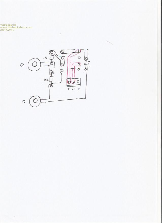 The gate driver board will also need to get its dc power from the IR2110 board, so three connections, and three wires will be required. As drawn, the chip and components will be on the underside of the board. That will reduce the height, and allow room for a big screw terminal electrolytic to mount right over the top of the whole assembly right between the + and - connections to the H bridge. Cheers, Tony. |
||||
| Warpspeed Guru Joined: 09/08/2007 Location: AustraliaPosts: 4406 |
Grogster, the way I ran my big aluminium interconnections: 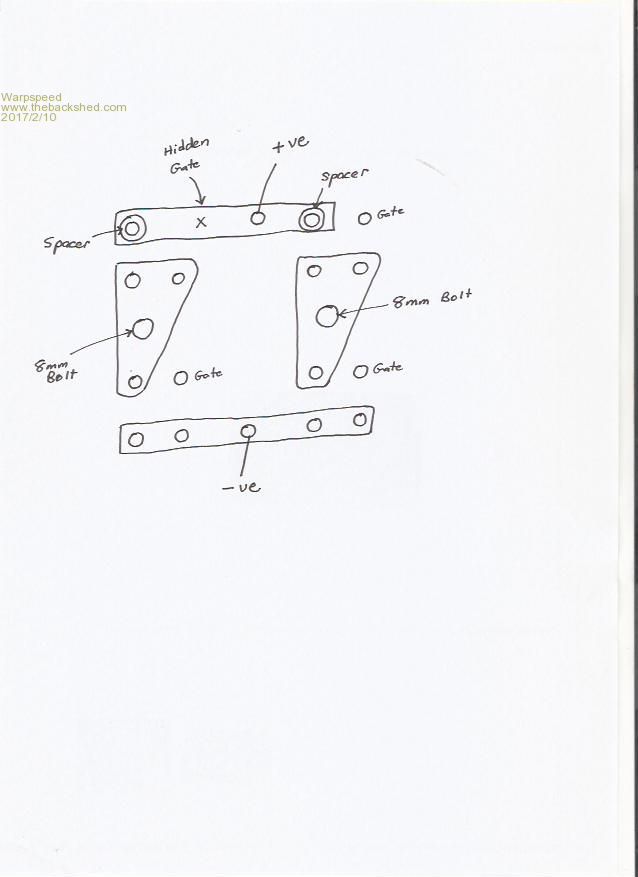 The positive connection running across the top, (between the two drains) was elevated by placing steel spacers between the mosfet drain connections and the aluminium strip to clear the gate connection of the upper left mosfet. I drilled an access hole through this, so I could get a screwdriver onto the otherwise hidden gate connection underneath. A similar system would allow the drain to drain interconnection to pass right over the top of your upper left circuit board. Two monster wires are going to be coming from the toroid primary. In my case I used 8mm bolts and big lugs. This can put a big strain on the source and drain screws. What I did was make two (6mm) thick triangular aluminium plates to bolt onto both source screws plus the drain screw. That makes for a very rigid termination point for the heavy toroid wires, that will not flex and possibly fatigue the mosfet connections. For the two lower mosfets I ran an aluminium connection right across all four source screws. It involves a bit of fiddly work to get all the hole centres correct. But once all these parts are made, it all goes together and comes apart very easily. Cheers, Tony. |
||||
Grogster Admin Group Joined: 31/12/2012 Location: New ZealandPosts: 9308 |
Awesome, thanks for those pointers and diagrams. I will alter my layouts. The PCB layout I posted above, was only a draft, so nowhere near the finished design, but there is not actually that much in the 4452 driver boards. The three-way header is for the positive, ground, and gate drive signal wires - the three you were talking about in your post above. Totally agree about the toroid wires stressing the MOSFET connections, and was thinking something would have to be done there too. Smoke makes things work. When the smoke gets out, it stops! |
||||
| Warpspeed Guru Joined: 09/08/2007 Location: AustraliaPosts: 4406 |
My camera is FUBAR, but I just had an inspiration. Sat the whole thing on my scanner. Its a crappy picture, but its there. The bolts for the toroid lugs are 6mm not 8mm. And those are not mosfets but large triacs that are the same SOT-227 package but only have three screws. Its really just a mechanical mock up of what I intended to do but never went through with it. 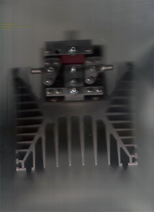 Cheers, Tony. |
||||
Grogster Admin Group Joined: 31/12/2012 Location: New ZealandPosts: 9308 |
Awesome - keep the inpiration coming!  Here is my latest mock-up then: 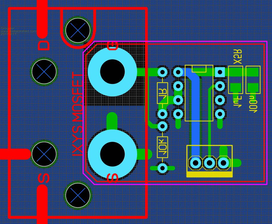 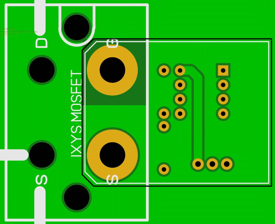 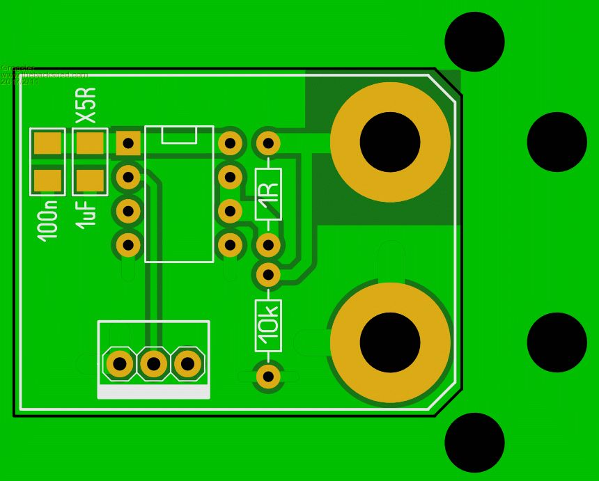 Again, this is just conceptual/draft playing about, but it will become something I can order, after a little more playing around. I would love for you to expand on how you were thinking of adding the big juicy electro(or electro's), as I can't quite see that in my head yet, but you obviously can.... Having gone this far, I would like to get authentic electro's too - do you have any reconsiderations? Perhaps Vericon again? Smoke makes things work. When the smoke gets out, it stops! |
||||
| Warpspeed Guru Joined: 09/08/2007 Location: AustraliaPosts: 4406 |
Excellent !! I took the big electro off that mock up to use on its successor, but will put it back in place and attempt another picture. I used a heatsink I already had, and had to work around that. The four mosfets are bolted to a 6mm thick "L" bracket which in turn bolts to the heatsink. Its a messy arrangment, but I just used what I had on hand. A big flat heatsink would be much neater for this, and more efficient. Arguably the best low ESR electrolytics are the European Evox RIFA. These are horribly expensive new, but come up on e-bay secondhand all the time. I just bought four of them yesterday 47,000uF 100v for A$225.00 At a guess these might be around A$160.00 each new. This is the type of thing: http://www.ebay.com.au/itm/1pcs-RIFA-169-Series-33000UF70V-audio-electrolytic-capacitor-75-120mm-/311781215585?hash=item 48979bcd61:g:VlIAAOSwZQRYfGAC These were not there a few days ago when I was looking. They come and go, but there is often something secondhand on e-bay. These PEH 169 and 200 capacitors are premium quality long life low ESR capacitors. The above 33,000uF 63 volt for example, has an rms ripple current rating of 71 amps at 50C and 10Khz, and an esr of 5 milliohms at 10 Khz. http://www.kemet.com/Lists/ProductCatalog/Attachments/375/KEM_A4035_PEH169_85C.pdf Cheers, Tony. |
||||
| Warpspeed Guru Joined: 09/08/2007 Location: AustraliaPosts: 4406 |
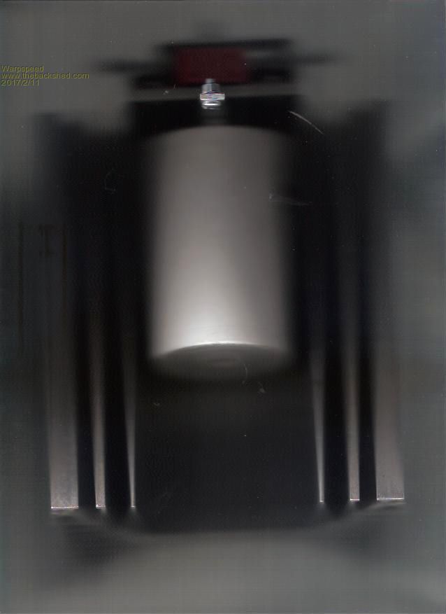 This is an even more terrible picture, but the electrolytic is mounted underneath the bridge. The ground terminal of the electrolytic goes through and is bolted to the heatsink "L" bracket and also bolts onto the negative side of the H bridge. Positive side of the electrolytic goes to the screw in the foreground, and also goes up through an insulated hole in the "L" bracket, through the middle of the (orange) current sensor to the raised aluminium link bar bridging the two drains. The orange sensor is a 150 amp Hall sensor which was going to support the main circuit board. A much better way to do this would be with a flat heatsink and the electrolytic mounted on top of everything else. I made things much more difficult for myself by wanting to use this particular heatsink because I already have several and wished to use them up. 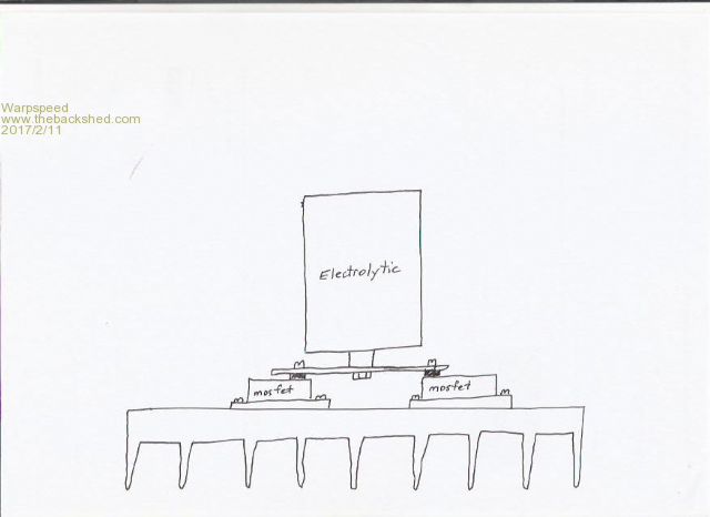 Cheers, Tony. |
||||
Grogster Admin Group Joined: 31/12/2012 Location: New ZealandPosts: 9308 |
Lovely, thanks.  Even a blurry photo is still useful to visualize how you did it. Drawing is even better. I will have a play about with these concepts. With the RIFA electro's: - How can you be sure they are any good buying from a Chinese eBay seller? Could they not also be fake ones, sold at great mark-up cos they know these ones are normally very expensive? - If genuine, how much reliablity can you put in 2nd hand caps? Smoke makes things work. When the smoke gets out, it stops! |
||||
| Warpspeed Guru Joined: 09/08/2007 Location: AustraliaPosts: 4406 |
These are second hand, and sold in very limited numbers so they are not fake. They will have been salvaged from old equipment. I have bought a good many of these from China over the last few years, they will have a few very slight scratches and dings but are otherwise excellent. Have never had any problems with them. Sometimes the clue is that they are obsolete types, for instance 70 volt rating suggests they might be quite old. The standard these days is 63 volts or 100 volts rating. They will be premium quality and the real thing for sure, but definitely not new. Once you have all the parts in front of you, its then a case of seeing how it can all fit together in a logical way. Cheers, Tony. |
||||
Grogster Admin Group Joined: 31/12/2012 Location: New ZealandPosts: 9308 |
If they are premium and the real-deal, how many should you use in an inverter project like this? As they are premium caps, does that mean you can get away with less of them or do you still need to aim for around 100,000uF of caps? Smoke makes things work. When the smoke gets out, it stops! |
||||
| Warpspeed Guru Joined: 09/08/2007 Location: AustraliaPosts: 4406 |
This shows the orange Hall current sensor and the drain bridging bar immediately on top. 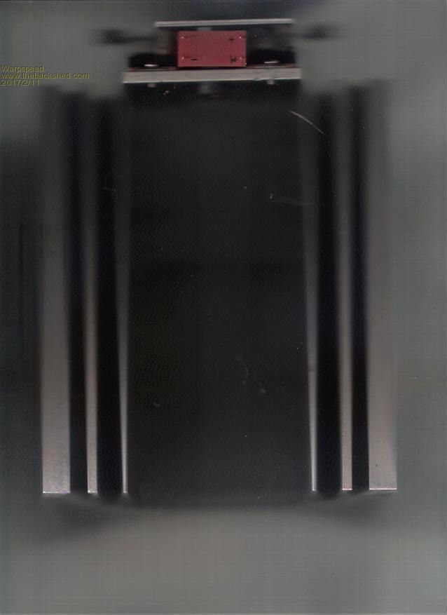 The RIFA capacitor with its two long 5mm threaded rods. 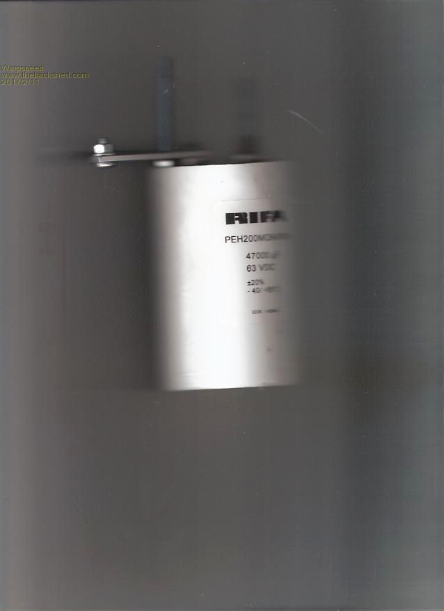 Cheers, Tony. |
||||
| Warpspeed Guru Joined: 09/08/2007 Location: AustraliaPosts: 4406 |
The main function of this capacitor is to reduce very short voltage spikes across the H bridge, a job it should do easily with only 5 milliohms of series esr. It will also reduce much of the 20 Khz ripple frequency which could disturb other equipment connected to the battery. The main 100 Hz pulsing current will be only be slightly reduced. But hopefully the inverter is located close enough to the battery for that not to be a problem. You could always fit a large capacitor bank if required, but the important thing is voltage spike reduction which requires something pretty good, right up close and intimate with the H bridge. What you have a bit further away is much less critical. Cheers, Tony. |
||||