|

|
Forum Index : Electronics : building an Inverter from scratch
| Author | Message | ||||
oztules Guru Joined: 26/07/2007 Location: AustraliaPosts: 1686 |
HY4008 x 4( 1 fet per leg ) 2.5kw..... getting hot fairly fast on the SPWM pair, not too bad on the 50kz square wave pair... over 50 amps average through those little legs is a bother as I have them fairly long for the to247 versions I have. Did not measure the peak currents, but they would have been well over 100 amps I reckon.... easily.... This is on a clockman board designed for 6/leg 1.5kw stays cool.... very cool considering the 30 amps going through it. Will add some more fets soon... and see what happens. ...........oztules Village idiot...or... just another hack out of his depth |
||||
| Tinker Guru Joined: 07/11/2007 Location: AustraliaPosts: 1904 |
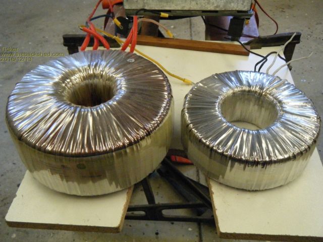
Thanks oztules,, I will be doing a similar test in a few days when I have wound on the new primary to another test toroid. This one is from the "well known Australian manufacturer", a 2500VA version. Just for a laugh I placed it next to an aerosharp toroid for comparison:  The one on the left is the aerosharp 3000VA. 20% difference in power, difference in size?? Then I weighed each (fully wound): Aerosharp, 3000VA:21kg right side, 2500VA:11kg I think the "overrated" comment in an earlier message holds water. Klaus |
||||
oztules Guru Joined: 26/07/2007 Location: AustraliaPosts: 1686 |
Thats a truly massive difference. To be fair, the aerosharo is designed for no cooling, and true continuous operation, it is a true 3kw unit. The other one is more a transient device. I dont think it is expected to run full power for long periods like a grid tie would. Most people buying expensive inverters will probably use small battery banks with not enough solar.... so long runs are an anathema to them. A short run with high power start up consideration is probably more important for most folks out there. That aerosharp will run 8kw for short periods, which is probably enough for most applications, and run 3kw continuous the rest of the time. I overdesign, so I can run 6kw continuous with twin or triple cores. Over here we tend to treat the victrons as toys for the same reasons, except they lack the start up as well..... If I cant start up 5hp single and 10hp three phase rotary converters.....well... it is not a real inverter  Interestingly, before I started to play over here, no off grid house would own an electric jug, or toaster, had modest microwaves at best... but usually none, gas fridges, gas water heating, gas stoves, and only used electricity warily.. oh, and ran the generator a fair bit for charging... and more particularly for washing machines with water heating incorporated.... oh and gravity water systems, that needed the generator to drive the pump that filled the header tanks. Now I see jugs, real double door fridges with ice makers included, 700 liter freezers, electric hot water systems, air conditioning, jaffle irons, toasters...85 inch tv's , pressure constant flow water systems.....you name it. Cheap solar is slowly changing things, and the inverters will need to catch up. No one but the tree huggers will be buying smaller units any more for whole of house usage... unless they want to live in a cave. They will need to be able to run 2-4kw continuous, with 20kw of surge available....8kw for 15 min runs etc or they won't be in the race.... and still have overhead for the water pump to cut in when needed. There is not a snowflakes hope in hell of my wife living with the privations of the normal off grid house... none. If she had to think about what she was running at any time, or not run this whilst that is running... I would be flayed. These grubby little inverters can do all of that and more.... who knew how simple it was. Generators just don't get used now.... and the 13hp honda's cant run the loads like the inverters can.. the world is changing....and AC coupling is a complete waste of time now. ...........oztules Village idiot...or... just another hack out of his depth |
||||
| Warpspeed Guru Joined: 09/08/2007 Location: AustraliaPosts: 4406 |
Haha oZ. The number one rule (in the inverter world) never send a boy to do a man's job. Cheers, Tony. |
||||
Madness Guru Joined: 08/10/2011 Location: AustraliaPosts: 2498 |
I regularly come into contact with (and I am sure many others do too) people who think off grid solar is a few low power lights and perhaps a small inverter to run a small tv occasionally and perhaps the odd small power tool. A week ago I installed a 10KW AC that draws up to 3KW continuously I have had it running at full power with the oven 2400W, washing machine with the heater on 2400W plus the rest of the house which would be around 600W at that time. I could run all the above at night but the battery bank would get discharged more than I would like. However, while the sun is shining I am just drawing a little from the battery bank with all those loads on with my present bank of panels. I am looking to add another 5KW of panels which will run all the above and still be charging. Although the main reason for the extra panels is so to keep the batteries charged during extended periods of wet weather. If someone could come up with a huge DIY battery bank that would be the ultimate for me. There are only 10 types of people in the world: those who understand binary, and those who don't. |
||||
| Warpspeed Guru Joined: 09/08/2007 Location: AustraliaPosts: 4406 |
Batteries are the biggest hurdle. I have been hoping the GMH would bring the Chevy volt electric car to Australia. That would have given us a source of large lithium batteries from pranged and written off vehicles. You can buy a 16Kwh (96 x 45Ah cells) second hand battery in the US for about $1,500 Wouldn't that be nice. Cheers, Tony. |
||||
Madness Guru Joined: 08/10/2011 Location: AustraliaPosts: 2498 |
I was thinking something like DIY salt water batteries, I know they are large but that does not matter for off grid. As far as I know you need Aluminium, Copper, Gypsum and salt water. But that really should be in a topic of its own. There are only 10 types of people in the world: those who understand binary, and those who don't. |
||||
oztules Guru Joined: 26/07/2007 Location: AustraliaPosts: 1686 |
Mad..... "If someone could come up with a huge DIY battery bank that would be the ultimate for me." From the looks of it, you have built a 8 or 9kw inverter for a handful of dollars.... thats pretty much ultimate to start with I should think. Were you referring to the 8010 unit?... couldn't be the trace at that power level. ........oztules Village idiot...or... just another hack out of his depth |
||||
Madness Guru Joined: 08/10/2011 Location: AustraliaPosts: 2498 |
Hi Oz, Yes correct it is the Inverter I have built or should I say am building as I am still working on improving the output quality. The 2 Trace Inverters I have are rated as 4500W I have seen one go to 5KW for a few minutes, I am not sure what it would do above that as I don't want to blow it up. Also the Trace will not start my metal abrasive saw, the homemade one doesn't blink at it. What I really love is the ability to be able to thrash the one I have built and not worry if it goes up in smoke because I can fix it easily. (not that I am expecting it would) And once again you are correct having built the Inverter is the Ultimate. Building big off grid batteries is next in line. Panels are cheap, charge controllers can be built cheap, we can build inverters cheap but buying batteries to keep up with "living off grid" is still quite expensive for most people. I am doing well with my bank of resurrected golf cart batteries but they need a lot of maintenance, just topping up water in 216 individual cells is a pain in the rear. There are only 10 types of people in the world: those who understand binary, and those who don't. |
||||
| Warpspeed Guru Joined: 09/08/2007 Location: AustraliaPosts: 4406 |
As inverter power rises, it quickly becomes apparent that higher battery voltages are a necessity. There will always be the dreamers asking for a circuit to build a 5Kw 12v inverter to run off the single battery in their car.'  ' 'But for serious off grid applications, if you need many Kwh of battery storage, its a lot more efficient (and dangerous) to have a battery that can directly power an inverter at several hundred volts of dc power, just as the EV people are already doing. I already have a system running here right now that uses a regulated +/- 230 volt dc bus to dive a pure sinewave inverter that generates 240v rms directly with an unfiltered actual measured distortion of around 2.5%. And its not the usual PWM circuit you might be expecting. This uses a multi stepped output, rather like a very high power digital to analog converter to convert +ve and -ve dc supplies to a many stepped sine wave. My camera is not that great, it will not focus up close. My small primitive experimental prototype inverter uses only 10 steps up and then 10 steps down on the +ve half cycle, and another 10 steps down and up on the negative half cycle. That is 21 steps peak to peak. Its only 1.6 Kw continuous rating but is happily handling surges of several times that. Its been running trouble free for almost a year now, and has survived a lot of abuse. I am now in the process of building it up properly but in 3Kw form, with 81 steps peak to peak and much lower unfiltered harmonic distortion. It uses multiple (5) small toroidal output transformers, but they are readily available off the shelf items from Altronics. Five relatively small 300Va toroids are easier to package than one multi kilowatt monster toroid. This style of inverter can be built with 3Kw or 5Kw continuous rating, with a surge rating of several times that with either 300Va or 500Va Altronics transformers. But best of all it is completely bi directional, and so it is very happy with very low power factor loads, that can throw a lot of out of phase current back at the inverter. It starts outrageously large motors with ease, considering its size. As the low voltage toroidal transformer inverters here have been so popular, and so successful, I don't know if there will be much interest in this very different approach. Probably not I am thinking. But anyhow, its something rather different that works, is very easy to build, and is a really tough little bastard I have not yet succeeded in blowing up. What makes it easy to build is that it switches at only a few hundred Hz, uses very tough IGBTs (not the more fragile mosfets) and there is no 20 Khz high frequency PWM switching which seems to be causing people so much grief when paralleling up multiple mosfets. So its all far less critical to build, with much less likelihood of letting the smoke out. Cheers, Tony. |
||||
oztules Guru Joined: 26/07/2007 Location: AustraliaPosts: 1686 |
Most interesting Warp.... I like the idea. I was looking at 340v DC and use that direct with the 8010.... but this looks interesting too. Be happy to see you expand on it. .........oztules Village idiot...or... just another hack out of his depth |
||||
| Warpspeed Guru Joined: 09/08/2007 Location: AustraliaPosts: 4406 |
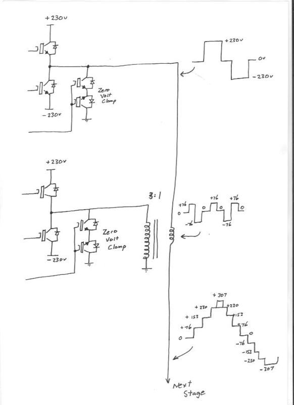
The basic idea is to start off with a simple half bridge inverter, plus a ground clamp that can hard switch its output to either +230v dc, ground, or -230v dc. Next we add a second identical half bridge inverter, but of much lower power that drives a 3:1 step down transformer. The output of the secondary winding will switch between +76.7V, zero volts (effective short across the winding) and -76.7v. By connecting this secondary winding in series with the big first inverter and switching both inverters in correct sequence, we can generate voltage steps of 0v 76.7v, 153.3v, 230v, and 306.7v. That would give us a crude sine wave of four steps up, zero, and four steps down. Nine steps peak to peak. But with the advantage of getting 306.7 volts peak from only a 230v dc source. Now we can add to that a third inverter with a 9:1 transformer to generate 25.5 volt steps that are spaced evenly between the 76.7 volt steps. Our sinewave starts looking much nicer, and our achievable peak goes up another 25.5 volts to 332.2v. We can go to a fourth inverter with 27:1 transformer and reach 81 steps peak to peak with only 8.5 volt steps and very low harmonic distortion, and our peak achievable voltage becomes 340.7v. Ain't that wonderful ! That should get you 240v rms from 230 v dc supplies, and it will too under no load. Absolutely flat out, it will be more like 230v rms output for 230v dc input. But at least you would be able to do it with 230v dc supply and not 340v dc supply which makes a significant difference. The advantages are many. All three (or four) inverters are identical except for the transformer, so identical circuit boards can be used. The transformers are all off the shelf items. I am using three 24v transformers in series for the 3:1, and one 24v transformer for the 9:1, and a smaller 160Va 12v transformer with turns removed for the 27:1 Cheers, Tony. |
||||
oztules Guru Joined: 26/07/2007 Location: AustraliaPosts: 1686 |
Pic of how that works will be most useful Warp.making my head spin wondering how you gonna sequence this simply. Tinker. Four fets installed per leg... easily goes to 15kw surges to start the lathe. Current control seems to be very sweet. No sign of failure. simply stops the unit.... The Lathe goes from hardly a noise... to trying to click the on relay, to stronger relay noise, to motor burst into life without hesitation. All the current settings up to that point ... the inverter stops smoothly, the back emf from the failed motor start causes no drama.... very nice to see..... gee there must be some current slop in there somewhere.... but it runs perfectly.... starting to feel good about the scr stop circuit.... but it does not seem to consistently ( across different boards) work with the same values  .....oztules Village idiot...or... just another hack out of his depth |
||||
| Warpspeed Guru Joined: 09/08/2007 Location: AustraliaPosts: 4406 |
Still getting an HTTP 500 server error. No pictures possible yet I am afraid. Ah, just had an inspiration. Here is a link to the same topic I posted on another Forum. http://www.edaboard.com/thread338191.html I did a sketch there of the principle, but it came out looking more like a sawtooth waveform, which it obviously is not. Its a simple idea, its just difficult to put into words. Cheers, Tony. |
||||
oztules Guru Joined: 26/07/2007 Location: AustraliaPosts: 1686 |
Need to be a member to see them more than big thumbnails. If you like, email them to me or glen to get them modded to go on this system. I would just take a screen shot etc. Tinker, the current limiter problem seems to be me related.... I didn't look too closely at the scr's..... looked the same, but one sort is sensitive gate, and the others are non-sensitive gate.... duh  ......oztules Village idiot...or... just another hack out of his depth |
||||
| Warpspeed Guru Joined: 09/08/2007 Location: AustraliaPosts: 4406 |
I will try one more time to load an image. Nope, still HTTP error 500. I will try going through Photobucket.  Ah success ! Main high power inverter at the top hard switches between +230v, short to ground, and -230v Next lower power inverter does the same thing, but through a 3:1 step down transformer to generate (230/3) or 76.7 volt steps. Next stage in the chain is again identical, but with a 9:1 step down transformer to add 25.6 volt steps between the 76.7 volt steps. Last stage is very low power, with a 27:1 step down transformer to add 8.5 volt steps. Final result will give 81 steps peak to peak. The thread on the other Forum is 18 months old, and I have learned a great deal since then. If there is any interest I can go much deeper into it with schematics, more pictures and EPROM data. Cheers, Tony. |
||||
| Warpspeed Guru Joined: 09/08/2007 Location: AustraliaPosts: 4406 |
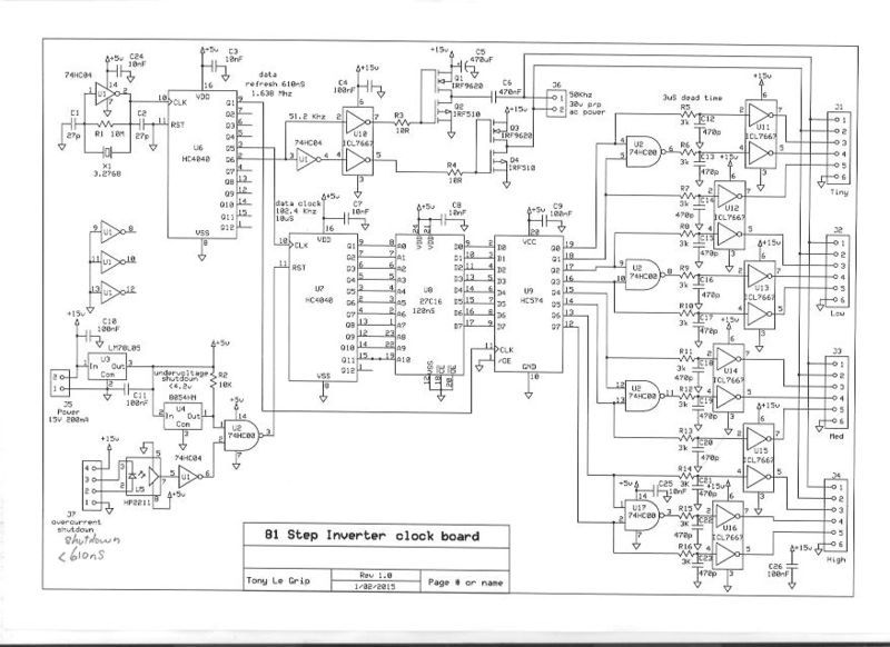
 This generates all the waveforms for four inverters. It scans a 2K x 8 EPROM fifty times per second. Each 20mS cycle sequentially scans through 2048 addresses (one address each 10uS) So we can turn things on or off by changing the EPROM data with 10uS resolution. Each voltage step is fixed in amplitude, but we have great flexibility in determining when it switches, so we can construct a fairly accurate sine wave with constantly varying slope. Address zero is the zero crossing point at the beginning of a positive half cycle. A current limit input forces the EPROM address to zero effectively producing a zero output voltage. When current limit is removed a new cycle stats off from the zero crossing. Because a ripple counter is used for address incrementing, and the EPROM address decoding is not perfect, there is a burst of noise during every address change. The latch U9 ensures clean date output as it is clocked after the EPROM data is guaranteed stable. Its pretty simple dumb logic, no software, but it works fine. Current limit is very fast, it can shut down the fun in less than a microsecond. The H bridge drive at the top of the circuit provides 30v peak to peak 50 Khz voltage that provides isolated dc power to the twelve isolated gate driver circuits via pulse transformers. A similar board but with only three inverter drivers (not four) has been running for almost a year trouble free providing a 27 step peak to peak 240 volts. Cheers, Tony. |
||||
| Warpspeed Guru Joined: 09/08/2007 Location: AustraliaPosts: 4406 |
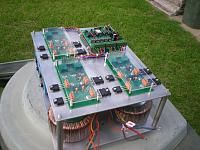
 This is the 1.5 Kw prototype about 18 months ago. It was tested and running, but all the transformer connections were made by crocodile clips to get the winding phasing correct. All the power wiring had yet to be finalized when the picture was taken. This is what is powering my house right this minute. The new 3Kw 81 step version is complete and fully wired up, but I have to get more circuit boards made for it, which will probably be well after Christmas. I could just as easily have made it 5Kw, by just fitting larger transformers, but I don't need that amount of power right now. Something to do later maybe. Next step will be a 3Kw dc to dc converter to generate +/- 230v from a Lithium battery. Cheers, Tony. |
||||
| Tinker Guru Joined: 07/11/2007 Location: AustraliaPosts: 1904 |
Oztules, would you like to contribute a little more to my inverter understanding? You mention: " SPWM pair, not too bad on the 50kz square wave pair." How do you tell which is which? If you used my terminology: 1LO, 1HO, 2LO, 2HO. Thanks. Amazing that you can start big machines with just the 4 Mosfet bridge. I have just about finished re building the 16 x HY4008 inverter but am waiting for more 4 x HY4008 test results in my shed before connecting that monster toroid up. Warpspeed has an interesting solution, requires a bit more electronics though. Mind, the 230V DC might be a bit of a challenge from the battery angle. I have 16 lipo cells for a nominal 55VDC, I would need more than four times that number. Though they could be smaller I guess. Klaus |
||||
Madness Guru Joined: 08/10/2011 Location: AustraliaPosts: 2498 |
In my experience, if it works on a small transformer the big one makes no difference as you have soft start. While there would be advantages you would need to be very careful around those higher DC voltages, much more dangerous than AC. There are only 10 types of people in the world: those who understand binary, and those who don't. |
||||