
|

|
Forum Index : Electronics : nanoverter build
| Author | Message | ||||
| BenandAmber Guru Joined: 16/02/2019 Location: United StatesPosts: 961 |
I understand now Madness you want everything to be automatic and seamless A lot of great minds working together here the output can only be good be warned i am good parrot but Dumber than a box of rocks |
||||
| tinyt Guru Joined: 12/11/2017 Location: United StatesPosts: 438 |
I am using an arduino uno in another application powered with 12vdc at its VIN. The 12vdc comes from a buck converter powered by a 360 watts AC to 24vdc power supply. For this power supply, when I remove the AC, the 24vdc drops to zero very slowly. I have not checked what happens to the 12vdc buck converter during power off. When I re-apply the AC immediately after the 24vdc has dropped to zero, the arduino seems to hang-up. (Symptom is no power on beep and the LCD display is blank). But the flash code does not get corrupted. Using an AVR programmer, I found out that in the arduino, the fuse byte BOD Level is set to 2.7vdc. When I changed it to 4.3vdc, the hang-up disappears. I don't know if the fuse byte can be changed using the IDE. Maybe this is not related to the nanoverter. But maybe the low BOD Level and the presence of the bootloader together with voltage glitches (if they are present) can cause flash code corruption. |
||||
renewableMark Guru Joined: 09/12/2017 Location: AustraliaPosts: 1678 |
Maybe don't worry about it till you actually see it. I haven't seen it myself. Cheers Caveman Mark Off grid eastern Melb |
||||
| poida Guru Joined: 02/02/2017 Location: AustraliaPosts: 1418 |
After a 1/2 day running the inverter using the nanoverter control board, I have found it necessary to add few things to nano2 code. First, I added offsets for the two NTC thermistors. I found it hard to leave things alone when one thermistor was 5 degrees different to the other when both in the same temperature situation. Now we can adjust one or the other to suit a known temperature. Next I added some digital filtering of DC supply voltage. This was needed for the following to work. I added a timeout value for the low DC voltage cut-out. If this is set to 5 seconds, it means the DC supply has to remain below the cut-out setting for an uninterrupted 5 seconds before LV cut-out functions. This is useful to avoid LV cut-out when a fridge switches on, with the high current draw of a motor startup. This low voltage transient only persists for 1/4 second or so in the case of our fridges. Now the inverter can ride over these bumps and not prematurely cut-out due to short term DC LV situations. I added LCD backlight support. We can turn it on or off. I am running this code on the new house inverter. 2019-07-21_235452_nano2_5_ac_current_sensor_dc_signal.ino.zip Now the menu looks like this. I highlighted the parts needed to have the DC low voltage cut-out working. heat sink temp = 21 degC ch.2 toroid temp = 20 degC ch.7 1 - cal. DC volts 0.06 -> 50.40 V ch.1 2 - cal. AC current 0.01 -> 0.00 V ch.6 3 - cal. ACI offset 31.00 ADC counts 4 - cal. DC current 0.09 -> -45.0 A ch.3 5 - cal. DCI offset 508.00 ADC counts 6 - cal. AC output 0.32 -> 0 V AC ch.0 N - Toroid NTC offset 0 degC 7 - Toroid fan ON 70 degC 8 - Toroid fan OFF 50 degC 9 - Toroid shutdown 80 degC P - H.S. NTC offset -5 degC B - H.S. fan ON 50 degC C - H.S fan OFF 40 degC D - H.S. shutdown 60 degC E - AC output low limit 200 V F - LV cutoff voltage 48.0 V Q - LV time below 5.0 seconds A - Restart voltage 50.0 V G - over current limit 20.0 A H - enable/disable DC LV cutoff ON I - enable/disable over current cutoff OFF J - enable/disable AC under volt cutoff OFF K - enable/disable H.S. over temp cutoff ON L - enable/disable Toroid over temp cutoff ON M - enable/disable LCD backlight ON Z - zero E2PROM Y - put defaults into E2PROM wronger than a phone book full of wrong phone numbers |
||||
renewableMark Guru Joined: 09/12/2017 Location: AustraliaPosts: 1678 |
Nice work Poida, keeps evolving. This will be obvious for most but to get to the menu, have the nano plugged in, make sure your port is correct. Then click tools, there will be an option for serial monitor, click that. A new window will appear, in the bar at the top put in a question mark ? and hit enter. Cheers Caveman Mark Off grid eastern Melb |
||||
renewableMark Guru Joined: 09/12/2017 Location: AustraliaPosts: 1678 |
Ben was asking what fet to use for Q7& Q8 I used some of these just because I already had them. Basically you just need a N channel fet in to220 to fit in the hole. Ben is there an electronics shop nearby that you can go to and buy small quantities of parts? They don't need to be powerful they are just for switching the fans on and off. Might have something suitable in your junk box?? Cheers Caveman Mark Off grid eastern Melb |
||||
| poida Guru Joined: 02/02/2017 Location: AustraliaPosts: 1418 |
I used some T0-220 HY4008 I bought in quantity. Not going to use them in an inverter bridge so may as well see if they work... Anything that has a low-ish Vgs(th) The IRFZ44N things are well suited for the logic level gate drive voltages. Cost about 1/2 of nothing much, good for very little but extremely handy for micro controller type projects. I had RenewableMark over here for a bit of picking up stuff and dropping off other stuff and I could not repeat the power-up -1V glitch as described above. Maybe it was a bad dream and all we need is for Poida to take a few Cooper's Stouts and have a lie down? In other words, there is no problem with -1V spikes on the nanoverter 5V supply? But I saw it, I swear...mutter, mutter... wronger than a phone book full of wrong phone numbers |
||||
| kentfielddude Regular Member Joined: 09/05/2019 Location: United StatesPosts: 89 |
This is the output of pin 9 and 10 of nano 1 connected to my scope. The nano is not in the nanoinverter pcb. Do these waveform look right. I am a beginner scope user so I might be doing something wrong. 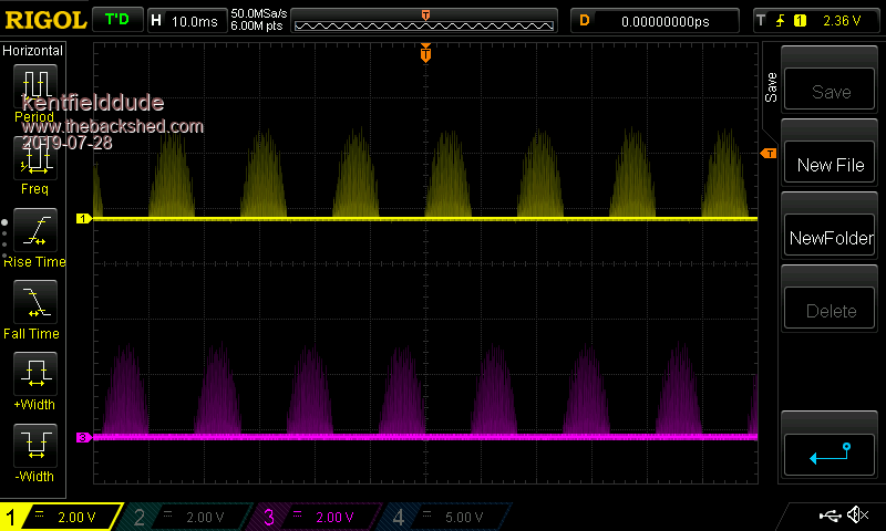 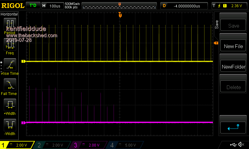 |
||||
| poida Guru Joined: 02/02/2017 Location: AustraliaPosts: 1418 |
These look correct. At all times when powered, nano1 produces very low duty cycle PWM output on those pins. It's not a problem to my mind since the gate drive IC outputs are disabled unless nano1 is commanded to run the inverter. wronger than a phone book full of wrong phone numbers |
||||
| poida Guru Joined: 02/02/2017 Location: AustraliaPosts: 1418 |
B & A to program the nanos, it's best to use a PC or laptop. download the Arduino programming software, install it. Then you need to add a special extra library to the Arduino programmer software. The library is called "LiquidCrystal_PCF8574" To install this, (once the Arduino program is running..) go to Tools, then Manage Libraries, then in the right of 3 text boxes type LiquidCrystal_PCF8574 hover over the result, and "select version" appears, chose what version is available and install it. Now you can compile the programs for both nano1 and nano2. You will need a driver for the cheap Chinese Nanos that come with the CH340x serial to USB chips. The genuine and more expensive Nanos use FTD232 serial to USB chips and the Arduino software comes with drivers already. The windows driver for CH340x is found (as well as other locations) at https://sparks.gogo.co.nz/ch340.html For any lunatic Mac users, of which I proudly include myself, the CH340x drivers are at https://github.com/adrianmihalko/ch340g-ch34g-ch34x-mac-os-x-driver and use version 1.5 Some nanos come with the current bootloader, others come with the old bootloader. They are not compatible! Not the same. but we can use either nanos anyway. Just choose, from the Arduino software, "tools", then "processor" either "ATMega328P" or "ATMega328P (old bootloader)" You can break anything if you choose the wrong one. You have to find out which bootloader you have for each of the nanos by trying one of the other methods. Of course, before compiling or uploading the codes, you must choose the correct board. (go to "Tools", then "board" and choose "Arduino Nano") It works reliably on both the Windows 7 PC I use at work and the Mac laptops and iMac I use at home. Now, to answer another question: No, I do not reccommend you use the Android phone to program the nanos. I have read poor reviews of the Android Arduino programmer software. But, by all means use the terminal program and a USB On The Go cable to configure already programmed nanos. I do this and it works perfectly. wronger than a phone book full of wrong phone numbers |
||||
| kentfielddude Regular Member Joined: 09/05/2019 Location: United StatesPosts: 89 |
SPWM on the esp32 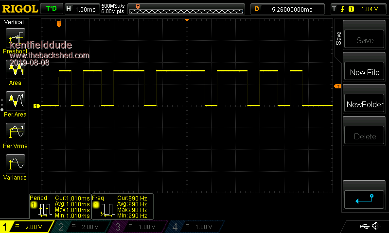 |
||||
| kentfielddude Regular Member Joined: 09/05/2019 Location: United StatesPosts: 89 |
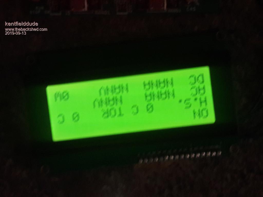 The display doesnt look right when I start it up. Might be a wrapping issue. I dont have anything plugged into the board |
||||
| poida Guru Joined: 02/02/2017 Location: AustraliaPosts: 1418 |
K: it's all OK. This is the correct display when no values are making any sense. To get a sensible AC volts, you need to give the ADC channel something to convert and then you use the serial terminal to define a calibration. Same for DC volts, DC Amps and all the rest. Try putting a 10K pot on the ntc inputs and see what happens. wronger than a phone book full of wrong phone numbers |
||||
| poida Guru Joined: 02/02/2017 Location: AustraliaPosts: 1418 |
When verifying correct operation of yet another nanoverter, I found a problem. It is centered around the 12V supply for the fans. Both the house inverter and the new one I am building use 2 x 12V 0.4A fans. The nanoverter 12V supply uses a 7812 regulator, taking Vin from the 15V supply. This 12V reg output is used for the 2 fans and also is Vin for the 7805 that supplies all the control and sensors. It's all working fine when no fans are switched on. The rev.D design (all designs actually) have 10uF and 104 caps on their outputs. 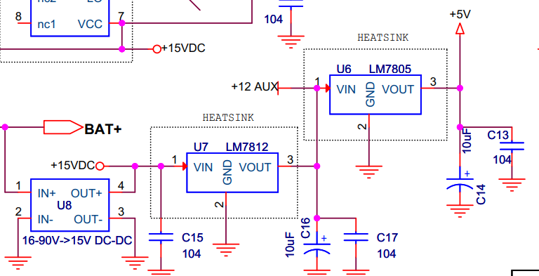 Here is what happens when one fan is switched on. Yellow is 5V output from 7805 1V/div Light Blue is 15V supply 5V/div Pink is 12V output from 7812, 2V/div 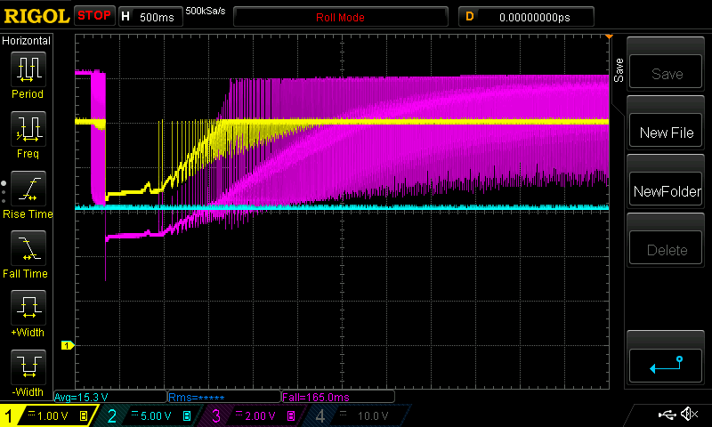 This is not good. Here is when I switch on the other fan (2 different types, both 0.4A) 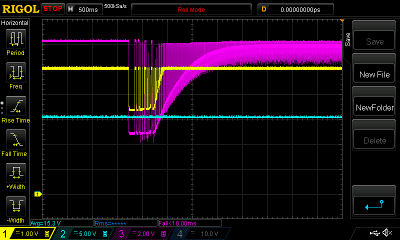 Not good either. Both times we can see the 5V supply drop to about 3.4V, and for over 1/2 a second. I think the nano microcontrollers are unlikely to give expected results during these situations. In the event of high inverter loads, both fans might be required to be on at the same time. Here is what happens: 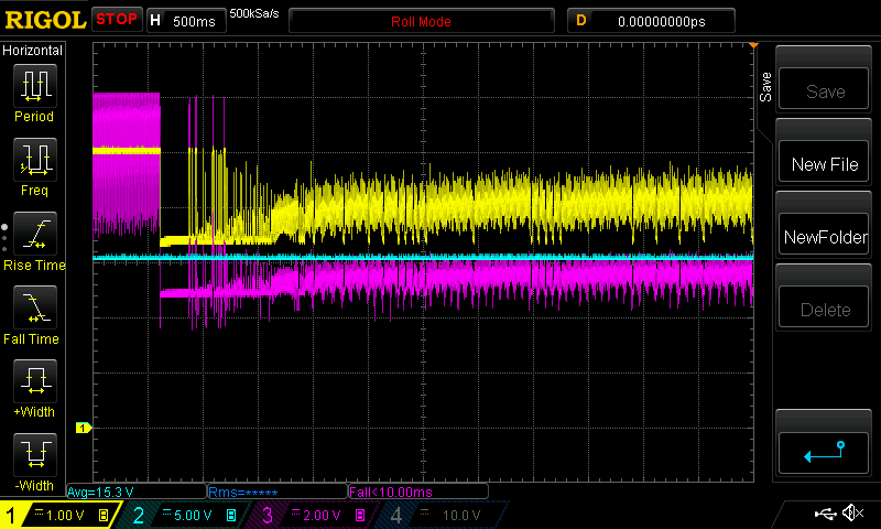 This is hopeless. Surely the inverter would just throw it's hands in the air and shout (with sparks and smoke) "I give up"? I replaced C16, the 7812 output 10uF with a 470uF. Things look better . Fan #1: 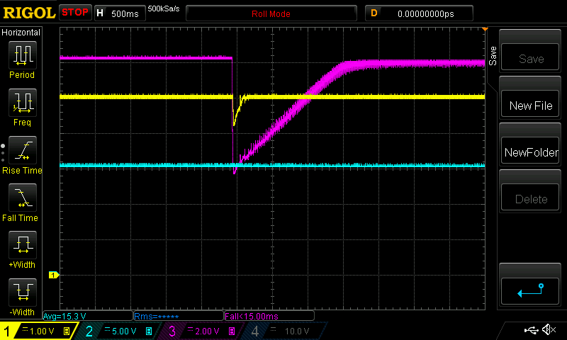 Fan #2: 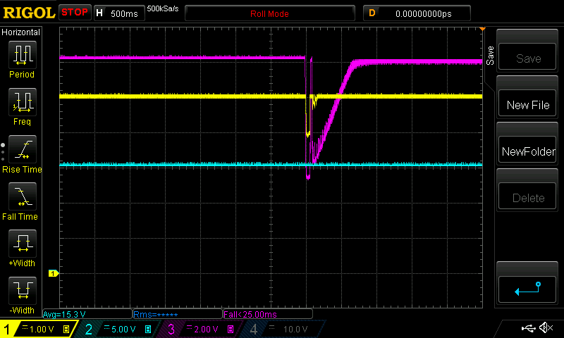 Both: 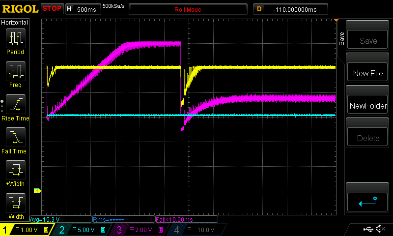 I think the 7812 can not deliver enough current for the two 0.4A fans. I had a good sized heatsink on the 7812 for these tests. And what's worse is the 5V supply is adversely effected by taking it's input from the poorly regulated output of the 7812. At all times, the 15V supply remained stable so at least that is working well. It's time to make some changes to the board: 1 - tonight I will cut the Vin pin track on the 7805, and connect it to 15V. This will make for a hotter running 7805 but a heatsink will be the fix. Replace the 10uf with 470uF I need to do this on the home inverter immediately. 2 - replace the 7812 with a zener diode/TIP35 combo that can provide 0.8A with ease. Until then, limit the home inverter loads to such that only one fan will ever need to run. OR get some separate 12V supply and hack that into the box. or cut the 12V track that powers the fans and use a separate supply for this. It will remove the large loads on 12V and let the board supply 5V without dropouts. The 7812 was bought from Jaycar . Their specs say 1 Amp. Dropout voltage is 2V at 1A output and 25C die temp. It seems to me that supplying the 7812 with 15V and expecting 1A out is pushing things a bit: 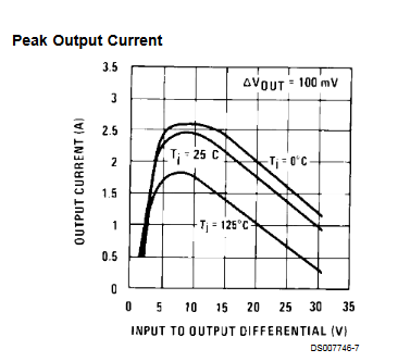 We are operating at the very steep part of this curve - near where the dropout voltage is. The 7812 has internal overload protection and internal over heating protection. Even with a good heatsink and the regulator at room temperature, the 7812 reduces output with the 0.8A load. when driving 0.8A the output droops slowly, due to the increasing internal die temperature. Edited 2019-10-22 09:19 by poida wronger than a phone book full of wrong phone numbers |
||||
| Warpspeed Guru Joined: 09/08/2007 Location: AustraliaPosts: 4406 |
Have you thought about using 230 volt fans and a small relay ? A good one can push a LOT more air and should overall, be a lot more power efficient. Cheers, Tony. |
||||
| Warpspeed Guru Joined: 09/08/2007 Location: AustraliaPosts: 4406 |
Blowers salvaged from old room heaters are almost silent, and move enough volume of air to transfer maybe 2.5Kw of heat into a room. Cheers, Tony. |
||||
renewableMark Guru Joined: 09/12/2017 Location: AustraliaPosts: 1678 |
Hmmmm, my nano control board has been running the house since mid March. House is off grid and entirely dependant on that. Both fans have run many times, I'll often walk past and can hear them both going. So yeah fix it, but I wouldn't panic. Cheers Caveman Mark Off grid eastern Melb |
||||
renewableMark Guru Joined: 09/12/2017 Location: AustraliaPosts: 1678 |
Sounds a bit redneck style, but could you just stick 2x 7812's in the board? I just checked, the holes fit 2 of them in there. 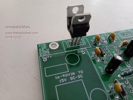 Edited 2019-10-22 10:11 by renewableMark Cheers Caveman Mark Off grid eastern Melb |
||||
| noneyabussiness Guru Joined: 31/07/2017 Location: AustraliaPosts: 512 |
Um... why not just run the fans from the 15v supply with a diode or 2 in series per fan.. don't use the 12v at all... 2 4007s with .4 amp through them will barely get warm, and can still supply mosfet control as same ground.. in fact ive run plenty of " 12v computer fans " from 15v let alone 13.6v... and easy to " hide " the diodes under some heatshink.. Edited 2019-10-22 18:06 by noneyabussiness I think it works !! |
||||
| poida Guru Joined: 02/02/2017 Location: AustraliaPosts: 1418 |
This is sort of what I am thinking will be the way to go. But for now, I have made the 5V supply independent of the 12V output. Acheivement #1 unlocked. And added the big cap to help the fans start up and run on the 12V output. The house inverter is safe now to run a fan. how about that? Now I can relax and wait for aliexpress to bring me my 70V ->15V 2A converters. wronger than a phone book full of wrong phone numbers |
||||