|

|
Forum Index : Electronics : Inverter PCB’s
| Author | Message | ||||
oztules Guru Joined: 26/07/2007 Location: AustraliaPosts: 1686 |
Ok, got home at 4.30, and decided to run the boards from last night. Dusted off the old single tranny, and we got this: Unit sounded happy too. close up just because I like it.... Now we put some more load on.... stop and start under load... no problems either.. This is just a pic to show the setup. Here we are with 4-5kw.... still no problems, in fact inverter near silent now. Both elements running So it is a nice unit, and have no drama's. It stops and starts under 5kw of load, just seems very stable. all good. ..........oztules Village idiot...or... just another hack out of his depth |
||||
Madness Guru Joined: 08/10/2011 Location: AustraliaPosts: 2498 |
Looking good Oz, you like to feel a bit of heat down there? Tomorrow morning I will be putting caps on the power board and giving it workout also. (providing nothing else gets in the way) BTW I am using the IR2010 Drivers voltage rating is lower than IR2110's but well above what we need at 200V. Amps increase from 2 to 3, won't make any difference though with Totem Pole drivers on my power board. There are only 10 types of people in the world: those who understand binary, and those who don't. |
||||
oztules Guru Joined: 26/07/2007 Location: AustraliaPosts: 1686 |
Yes, this was driving a clockman power board, with NO inductor. So there were no totems to save the day, and it still worked flawlessly. The tranny was under done, the inductor was not present, it still worked perfectly well, with no noises, and very small heating. Even 5kw did not cause the heat sinks any bother after 10 mins or so. So, If folks are having troubles, don't blame the inductor, or the totems or lack thereof... youve screwed something up.... maybe the 8010 soldering etc... folded pins on the drivers, or something else that is silly.... but kills the fun. The bigger drivers are fine, but they seem to make no major difference. I haven't tried the 22kw test tonight, but will in the morning... too damn cold now. ........oztules Village idiot...or... just another hack out of his depth |
||||
Madness Guru Joined: 08/10/2011 Location: AustraliaPosts: 2498 |
I would like to know why I have had different results also, I can drive 16 MOSFETs like you are there also with no problem. I doubt it is folded pins etc, what I do know is that I have had very good results with the Totem pole driver power board. Not once have I seen sharp spikes in the waveform or any of the other nasties that I was getting without the Totem Poles and 24 FETs. Might have to buy a Tee Pee! There are only 10 types of people in the world: those who understand binary, and those who don't. |
||||
renewableMark Guru Joined: 09/12/2017 Location: AustraliaPosts: 1678 |
Sorry if you felt any pressure from me, I certainly didn't wan't you to rush anything through. Anyway three cuts to tracks and a few different values placed isn't a big deal. I managed it! Cheers Caveman Mark Off grid eastern Melb |
||||
oztules Guru Joined: 26/07/2007 Location: AustraliaPosts: 1686 |
Will get to your big power card soon I hope, and see if I can find a difference. I do know this.. if it works. keep doing it. It is only a few parts, so the totem is a good deal, I just have not seen the need as yet... for reasons I can't fathom, our mileage varies markedly. My next iteration ... if there is one, will likely incorporate a totem arrangement.... but it won't be driven by necessity from the looks of it. Mine ( and your control board ) seems perfectly fine without it. .........oztules Village idiot...or... just another hack out of his depth |
||||
Madness Guru Joined: 08/10/2011 Location: AustraliaPosts: 2498 |
Essentially it is your Control Board Oz, the circuit is the same except for the Arduino Nano addition. What I am very happy about is that it works and works well, I have had a couple blowups but that was caused by my GTI failing due to my experiments. When that happened though the only components that failed were the MOSFETs. Everything else was unaffected including the Totem Pole transistors. Total cost of the extra components is well under $5 compared to the non Totem Pole version. I do plan to try the power board without the Totem Poles and with the IR2010 drivers. You just need to put links in place of the 20 ohm resistors and put another link across the outer pins of each tip 41C transistor. Leave out all the extra components and use 5R6 gate resistors and you have the original Ozinverter Power Board. There are only 10 types of people in the world: those who understand binary, and those who don't. |
||||
| Mulver Senior Member Joined: 27/02/2017 Location: AustraliaPosts: 160 |
Madness, I have not started ordering any parts, but i have been working on a clean parts list that i started when i got Clockmans boards, it still needs a lot of work on standardising the part numbers with both the Ozinverter and the Madinverter. Feel free to comment and recommend changes additions etc. I have just wipped through this thread and added your parts lists in. Yellow areas have formulas in them! Let me know what you think! 2018-05-15_213118_OGI_Parts_v2.zip Also the boards arrived!!!  THANKYOU!! THANKYOU!! |
||||
Madness Guru Joined: 08/10/2011 Location: AustraliaPosts: 2498 |
That is an impressive Spreadsheet Mulver, will make it much easier for people to do their parts ordering with all the links there. I have not looked really thoroughly at it but a couple things, on the control board 2 X 5V6 Zeners 13V Zener is now 18V. 2 X 40 Pin socket instead of 1 1 X bottle Electronic smoke with an insertion tool. All the Resistors on the Control Board are 0.25W buying a mixed bag of them will get most of them in one go and may work out cheaper. Thank you for your contribution, must have taken a lot of hours to put that together. There are only 10 types of people in the world: those who understand binary, and those who don't. |
||||
| johnmc Senior Member Joined: 21/01/2011 Location: AustraliaPosts: 282 |
Good Day Madness received my pcb's many thanks for your effort. cheers john johnmc |
||||
| yahoo2 Guru Joined: 05/04/2011 Location: AustraliaPosts: 1166 |
The silkscreen on a first batch is only a rough guide, as long as we end up with a final board to copy and a list of the alterations its all good. My only concern was that the board layers didn't have an error that we couldn't fix. You have done a great job. Yellow areas have formulas in them! Let me know what you think! OOH! PIVOT TABLES very noice  I have a spreadsheet that someone sent me, you enter home automation arguments in and it spits fully coded markup language out the other side, I have no clue how it works. Its like magic! gotta love excel I'm confused, no wait... maybe I'm not... |
||||
| noneyabussiness Guru Joined: 31/07/2017 Location: AustraliaPosts: 513 |
I was going to play devils advocate and suggest if you have the nano on board with the eg8010, have you thought about turning it on and off via the nano and serial communication. .. gets rid of the spurious signals from a dodgy switch ( the nano can do the heavy lifting with switch debounce ) and its solid on/off, 2 wires and a couple of lines of code... just a suggestion, i did write some code earlier that talks to the eg chip and works happily. . I think it works !! |
||||
Madness Guru Joined: 08/10/2011 Location: AustraliaPosts: 2498 |
The only problem I have had with the switch was using one from another PCB on these new PCBs which has a different pin configuration. I have not had any problem otherwise, I know Oz had some issues earlier on with resistors involved. Turning on the switch starts the soft start sequence which would give plenty of time for switch bounce to pass. While there are lots of things that could be done via serial communication the only one I can see that we need is to stop and start the EG8010. By pulling the TFB pin high it will shut down the Inverter safely, this is quite simple to do and this facility is on the PCB already. Telling the EG8010 to stop via the TFB is a very safe way to control it. If you wanted to use it as your primary control you could and just leave the switch to pin 6 connected to 5V. There is also the option to add RS485 which could be used to turn the Inverter on or off remotely if that was needed for some reason. There are only 10 types of people in the world: those who understand binary, and those who don't. |
||||
Madness Guru Joined: 08/10/2011 Location: AustraliaPosts: 2498 |
Good Day Madness received my pcb's many thanks for your effort. cheers john My pleasure John, I hope you have better luck than you have had. That cloud of smoke picture you posted before was impressive although I am sure you did not see it that way. We know these PCBs work, Oz has got the new control board running as have I and the power PCB is the same as what I have been using to run my house for over 12 months now. I will do PDF of the changes required on the control board to fix the few little errors that I made there. There are only 10 types of people in the world: those who understand binary, and those who don't. |
||||
renewableMark Guru Joined: 09/12/2017 Location: AustraliaPosts: 1678 |
All the Resistors on the Control Board are 0.25W buying a mixed bag of them will get most of them in one go and may work out cheaper. Oh crap, I have almost finished, but have used .5W hope that's ok? I thought it was just the new nano section that needed .25W Cheers Caveman Mark Off grid eastern Melb |
||||
Madness Guru Joined: 08/10/2011 Location: AustraliaPosts: 2498 |
0.5W will work fine they are just able to handle more power, just the smaller 0.25W ones fit in better. But if you bought them from Jaycar there 0.5W resistors are the same size as others 0.25W for some reason. Power board though is all 0.5W except for the 4 47 ohm snubbers and the 120ohm. See attached file for the Control Board Fixes.2018-05-16_075628_MAD_CONTROL_BOARD_MODS_REQUIRED.zip There are only 10 types of people in the world: those who understand binary, and those who don't. |
||||
oztules Guru Joined: 26/07/2007 Location: AustraliaPosts: 1686 |
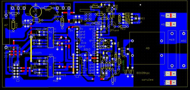
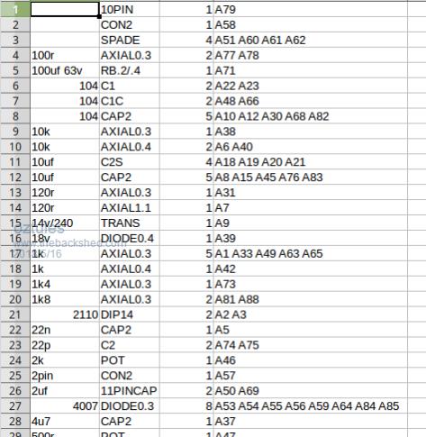
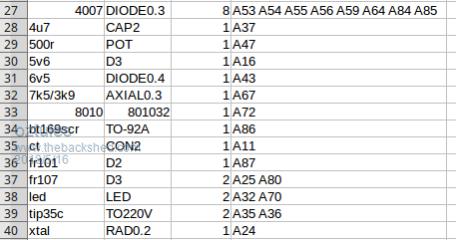
Ok mulver, as you know I'm not big on documentation... but I have cleaned up the pcb, so that it has output a BOM and made the screen shot show only the designation numbers. This should give a succinct overview of both mads and my boards, except for the nano addition. Clockmans board is basically the same, so it is fairly generic. So here it is with designates only  Here is the generated bill of materials.. top half  and bottom half. There are only 40 components on the control card.... very low count for such a powerful device.  Ok we I have built 2 of them in a few hours, both work perfectly, so I can only say... Build it carefully, watch your soldering, make sure the 8010 is properly soldered onto it's board. Check all the 32 pins from their post, back to the pin itself..... look for any dry joint there as well. Beware of the driver pins folding up... it happens, and looks just the same... Make sure your transformer ( VFB ) is sound. I had a dud the other night, but thats what you get with $1 tranny's. It is fine on the test power board with no caps, but deadly on the real thing. STEP 2. Do use 10-50amp circuit breakers when testing, then you will suffer no board damage, and very little other damage when you mess up. Once you see a soft start on the scope, and a good sine wave, chances are your good to go full power. You can see the results last night, where I just whipped the boards up, quick test, then 5kw.... so it is all true, they are plug and play, paint by numbers, but you still must take care on your first one to avoid disappointment. Don't try and do it all in an hour... I have had a lot of practice, so I can.... but take it steady. You can see from the rats nest on the bench, that layout and wires everywhere are not as important as they pretend it to be...... 5kw is nothing to be sneezed at, and the tranny was almost silent.... meaning there were no spurious wave forms in there... you can hear them clear as day if your messing up. So if your having difficulty, it will probably be a simple glaring mistake, involving the 8010 or the drivers. Try to keep the temp on the 8010 chip very temporary in nature. The on/off switch is pretty robust, as I gave it a good testing last night.... it goes unstable when the signals are not there, but does not seem to blow itself up either.... but makes strange noises in the transformer like it is going to blow... but doesn't. ........oztules Village idiot...or... just another hack out of his depth |
||||
Madness Guru Joined: 08/10/2011 Location: AustraliaPosts: 2498 |
Don't try and do it all in an hour... I have had a lot of practice, so I can.... but take it steady. ........oztules Agreed, the extra time you spend putting it together well could save a lot more time and frustration later on. There are only 10 types of people in the world: those who understand binary, and those who don't. |
||||
| Mulver Senior Member Joined: 27/02/2017 Location: AustraliaPosts: 160 |
I have made your changes Madness, Oztules i have not reviewed you list yet i will ASAP. 2018-05-16_084908_OGI_Parts_v3.zip |
||||
Madness Guru Joined: 08/10/2011 Location: AustraliaPosts: 2498 |
 You actually put the smoke in. You actually put the smoke in.There are only 10 types of people in the world: those who understand binary, and those who don't. |
||||