
|

|
Forum Index : Electronics : Stock Std Warpinverter
| Author | Message | ||||
renewableMark Guru Joined: 09/12/2017 Location: AustraliaPosts: 1678 |
I got some rubbish wire and wound 25 turns. This is what it looks like. 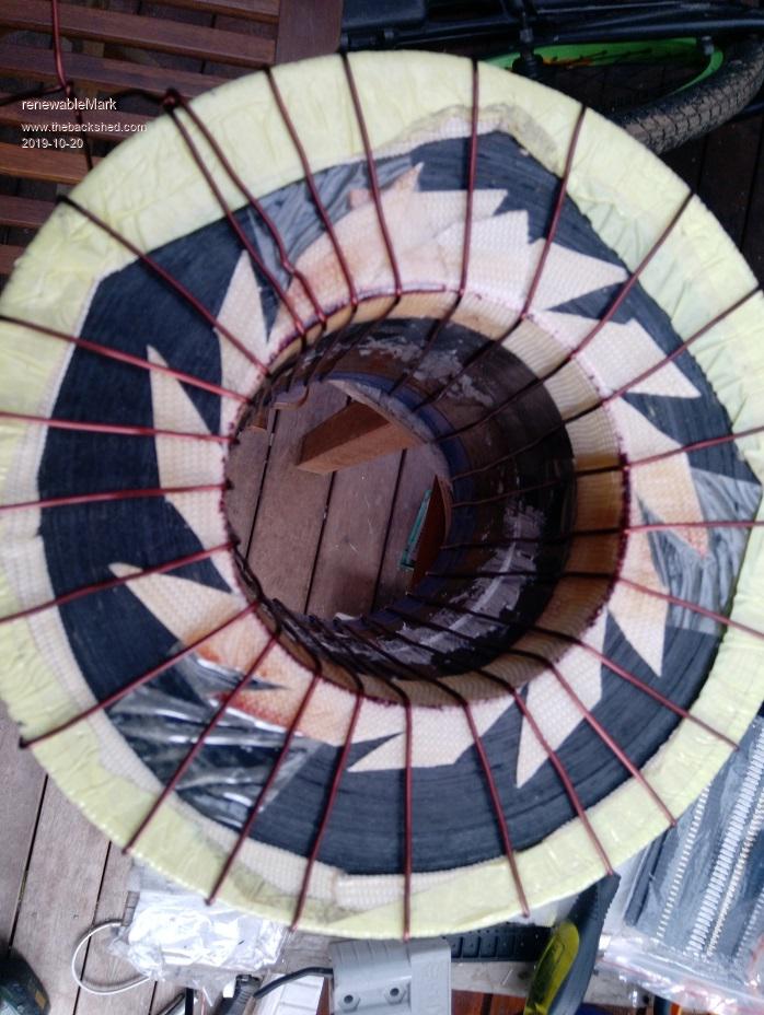 Just a bit worried considering I'll be using recyled wire there may end up being a short somewhere. I'd be inclined to do at least one mylar wrap between the 14 hands/windings. Could probably wind 2 hands and do a mylar. Keeping in mind doing the primary with small wires will take up a heap less room than single core 35mm2 so the extra 14 or 7 layers of mylar should hopefully not add too much thickness to the centre core. If they all start the same place and finish the same place it should end up being fairly neat. Cheers Caveman Mark Off grid eastern Melb |
||||
| Warpspeed Guru Joined: 09/08/2007 Location: AustraliaPosts: 4406 |
Sounds good Mark. Cheers, Tony. |
||||
renewableMark Guru Joined: 09/12/2017 Location: AustraliaPosts: 1678 |
I found the 5mm coreflute was too stiff to bend around nicely, so got some 3mm stuff. I put three layers on so far. 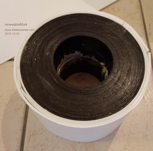 Tony, how many layers would you put on to reduce the capacitance? Recon I'll do a ply cap top and bottom as the coreflute won't take the pressure when pulling the wire tight around the corners. Also, I'm running low on mylar film, could I just use electrical tape? This one has no more than 80c. Mine have never gone anywhere near that. Or is it just safer/wiser to stick with mylar? 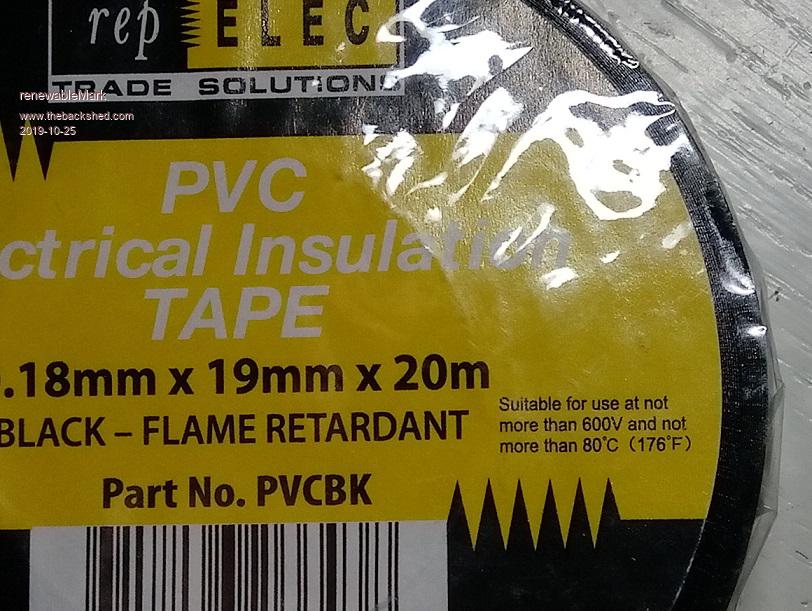 Cheers Caveman Mark Off grid eastern Melb |
||||
| Warpspeed Guru Joined: 09/08/2007 Location: AustraliaPosts: 4406 |
Its difficult to nail down an exact distance, its really a judgement call. But I would think 5mm to 6mm should be pretty effective, and anything more than that would be getting into the point of diminishing returns. I bought some polypropylene packing tape from Bunnings a while back: https://www.bunnings.com.au/bear-48mm-x-75m-clear-polypropylene-packaging-tape_p1661555 Polypropylene has some very good electrical properties and is o/k up to about 90 to 120 Celsius, and melts at 160 Celsius. The sticky part is a bit of a bugger, but its usable for some high voltage transformer applications, and its cheap. https://omnexus.specialchem.com/selection-guide/polypropylene-pp-plastic Edited 2019-10-25 10:54 by Warpspeed Cheers, Tony. |
||||
mackoffgrid Guru Joined: 13/03/2017 Location: AustraliaPosts: 460 |
Mark, I know it's too much to bother, But... It would be great to have two transformers wound onto the same size core, 1 with padding and a normal one. Then wait for Tony to receive his flash new cro (very jealous) to trial the two transformers. The winding technique I posted in my thread would also be an interesting comparison. Of-coarse this applies equally to any topology of inverter etc... |
||||
renewableMark Guru Joined: 09/12/2017 Location: AustraliaPosts: 1678 |
I already had the big torroid done. here on P2 Then the capacitence issue arrose with Tinkers build, hence me winding yet another one. This will have primary on first, then secondary. Same turns, same size torroids. 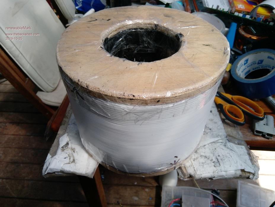 Here we go again. . Edited 2019-10-25 13:53 by renewableMark Cheers Caveman Mark Off grid eastern Melb |
||||
| Warpspeed Guru Joined: 09/08/2007 Location: AustraliaPosts: 4406 |
The new CRO is at least another week away at the very earliest. Cheers, Tony. |
||||
renewableMark Guru Joined: 09/12/2017 Location: AustraliaPosts: 1678 |
Don't worry Tony I can't whip out another transformer overnight. I don't even have a stockpile of straight wire as I wasn't expecting to wind another one. It will be interesting to see if it makes an improvement though. How would you test that anyway? Cheers Caveman Mark Off grid eastern Melb |
||||
| Warpspeed Guru Joined: 09/08/2007 Location: AustraliaPosts: 4406 |
What I have been thinking about doing Mark, is first make some measurements on my own inverter using a Hall sensor in the primary of each transformer. Just to get some idea of what might really be there in the way of current spikes. Then substitute a toroidal winding that I already have here. Its an Inspire 1.5Kw core with an original 135 volt primary of 135 turns wound straight over the core and with an original 230 volt secondary on top of that. Its not huge, but it should at least give some indications of the problem. Then have a look at that, connected across one of my inverters and judge how much difference there is between that and my E and I transformers on the same inverter. Next step would be to hot foot it around to your place Mark, and do the same testing on both your original large toroid, and your new latest large toriod. This will need to be done at your place with 48 volts, and a 48 volt inverter neither of which I have here. I haven't started any testing yet, but when I do, I will have a much better idea of what I will need to make up and what I will need to bring with me. From all of that, we should be able to get a pretty good handle on things, and make some sort of plan about what to do next. Its not a big drama, it all needs to be slowly and methodically worked through. Andrew sorted it all out, and so can we, and Klaus will benefit as well. Edited 2019-10-26 16:29 by Warpspeed Cheers, Tony. |
||||
mackoffgrid Guru Joined: 13/03/2017 Location: AustraliaPosts: 460 |
I look forward to seeing the results. And seeing it on the Rigol  Yup, big chokes sorted me out. I suspect you'll find big batteries and Toroids cause the the big inrush. I used the following and found them invaluable.  Hantek 600amp current clamp The website says it's bandwidth is 400Hz but it's not. Thats an error - it's really 100kHz + It certainly picked up current pulses with rise times of only a couple of micro seconds. The high volt diff probe is the other useful tool. I wish I had a Rigol cro today, mine just doesn't have a large enough memory to capture certain events. I was measuring the starting current of my compressor. It's zero to peak was about 53Amps for about 400mSec then drops rapidly to 7amps. (connected to street mains) cheers Andrew |
||||
| Warpspeed Guru Joined: 09/08/2007 Location: AustraliaPosts: 4406 |
I have quite a selection of Hall devices and current transformers here to try out. Not sure what will work best, which is why I would like to do a bit of testing on my own inverter first. Cheers, Tony. |
||||
renewableMark Guru Joined: 09/12/2017 Location: AustraliaPosts: 1678 |
Sounds like a good plan. My Warpinverter still needs to be assembled. Fair bit of work to do beefing up the locker and all the wiring yet. The new padded transformer need to be wound too, still no copper on it yet. I'll sing out when that's getting close to done. Cheers Caveman Mark Off grid eastern Melb |
||||
renewableMark Guru Joined: 09/12/2017 Location: AustraliaPosts: 1678 |
BTW since you said 5 to 6mm of packing I took one layer off leaving it with 6mm of packing. Yell out if you re consider before the copper starts. Cheers Caveman Mark Off grid eastern Melb |
||||
| Warpspeed Guru Joined: 09/08/2007 Location: AustraliaPosts: 4406 |
Two layers around the outside, and a couple of large "cut out washers" of the material stuck on each end should do very nicely. I don't know what you can do around the inside of the hole. Probably nothing without losing too much diameter. But any extra spacing material you can add there would be an advantage, even if its minimal. There is no mad rush, we are not working towards some time critical deadline. I would like to do a bit of testing and messing about here first, and get all my ducks in a row before heading off in your direction. Cheers, Tony. |
||||
renewableMark Guru Joined: 09/12/2017 Location: AustraliaPosts: 1678 |
I looked for that but couldn't find it, can you point me to it? Tony another thing we could try is move the primary winding on the First No1 torroid so it's sitting mostly to one side. It will be fairly easy to slip those primary windings around. I think that was what Andrew was talking about, I can't remember if it was the sec or primary though. One step closer, I got the buss bars done yesterday. 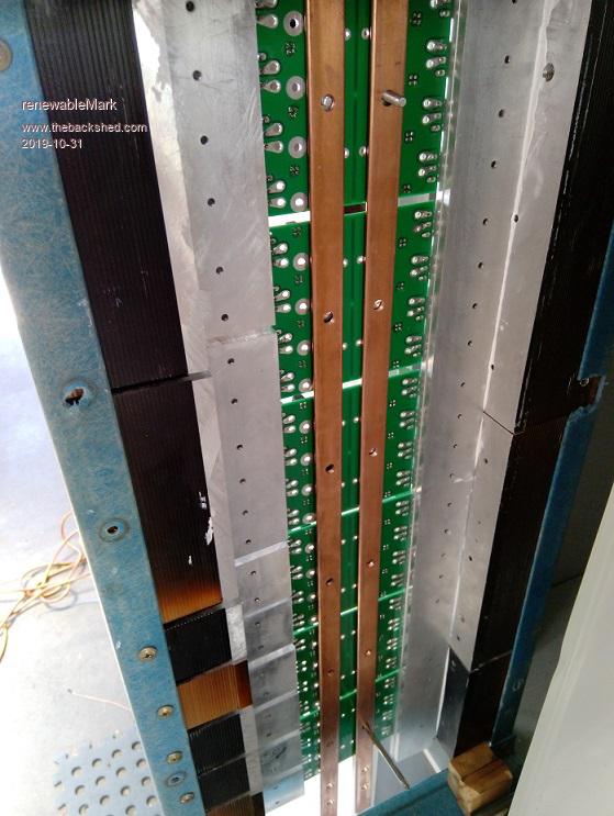 Cheers Caveman Mark Off grid eastern Melb |
||||
| Warpspeed Guru Joined: 09/08/2007 Location: AustraliaPosts: 4406 |
Very nice work there Mark, that is going to be a real show piece when its complete. Take your time, think it right through and do it right. With toroids, its always best to space each winding evenly right around the core in complete even layers. That will give the best and strongest coupling between primary and secondary, especially important under very heavy load. Placing a physical spacer between primary and secondary is a different thing altogether. As long as both windings go all the way around the core the slippery sneaky magnetic flux cannot find ways to escape and find short cuts around either winding. Cheers, Tony. |
||||
mackoffgrid Guru Joined: 13/03/2017 Location: AustraliaPosts: 460 |
Sorry Mark, it was posted in Tinker Warpverter Thread. Andrews comment on winding transformers to reduce ccapacitance I'm not going to try it - yet -  You're much more experienced than me at transformer winding  Cheers Andrew |
||||
| BenandAmber Guru Joined: 16/02/2019 Location: United StatesPosts: 961 |
That is one awesome inverter board be warned i am good parrot but Dumber than a box of rocks |
||||
renewableMark Guru Joined: 09/12/2017 Location: AustraliaPosts: 1678 |
It's actually 6 small boards assembled together. The top three power boards will be one inverter, the other three will be individual inverters. The driver boards fit on top of the power boards. And one control board sends signals to the driver board/s These power boards can also be used as a spwm inverter ala Madinverter/Ozinverter, with the use of a third (spwm)control board that can click in on top of the driver board. So you could use just one of the square power boards with 8 fets and make a little Spwm inverter or use the ribbon expansion cables either side and make one with 3 power boards and 24 fets. Or like I have done and make 4 individual inverters that will run the Warpinverter. Mackoffgrid designed it all, took me a while to understand the wiring and different set ups it can do, but once I did it becomes clear how clever the design is. Cheers Caveman Mark Off grid eastern Melb |
||||
renewableMark Guru Joined: 09/12/2017 Location: AustraliaPosts: 1678 |
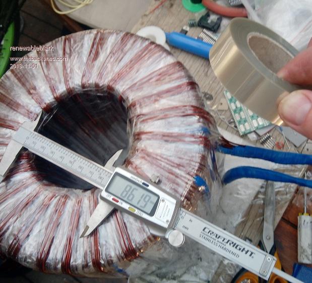 I have 10 layers/hands of 25 turns on so far. ID has dropped to 86mm from 100mm. 4 more winds to go, then a good wrap of the new mylar and onto the secondary. Tony, should I use the coreflute packing between the primary and the secondary as well? Got some more mylar film. ($18plus GST) It's from regal bleriot in rowville if anyone needs some. http://www.regalaustralia.com.au/ These guys in Adelaide sell it too. http://www.advancedthermalsupplies.com.au/index.php?route=product/category&path=61_71_121 Edited 2019-11-01 15:51 by renewableMark Cheers Caveman Mark Off grid eastern Melb |
||||