
|

|
Forum Index : Electronics : nanoverter build
| Author | Message | ||||
| tinyt Guru Joined: 12/11/2017 Location: United StatesPosts: 438 |
Digikey has a 1A .22V vf diode LSM115JE3 @$1.12. Maybe instead of looking for a low vf diode to clamp the 5v supply, try this. Add a regular diode in series with the input of the 7812 regulator. This is PCB bottom view. 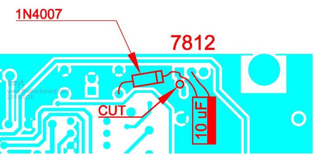 Maybe it will block the negative spike from flowing thru the 7812 and 7805 regulators. I have also added a 10uF filter at the 7812 input. The 7812 output might be slightly lower than 12 volts. Hopefully it should not affect whatever fan it will power. |
||||
| wiseguy Guru Joined: 21/06/2018 Location: AustraliaPosts: 1156 |
I am using just the nano1 with my own PCB layout. On board I have 12V & 5V, The 12V supply comes from one of those LM2576HV modules from Ali express like here , the 5V is like here I am running currently from a 30V input supply & have started and stopped a zillion times without any incident (to date). Whilst I agree the decaying ringing glitch captured on the CRO is undesirable and appears to exceed the neg. supply specifications I am not convinced that it is the root cause of the issue. Rather than trying to filter out or clamp the glitch my approach would be to try to find the source of the glitch and reduce it or kill it so it doesn't exist. If you trigger off the glitch and then go looking for what is happening around the place that coincides with the glitch, include the flyback switcher and its output diode, and outputs from the nano that drive the FET buffers etc, something is causing it. On page 272 there are some comments and guidelines to prevent Flash corruption that focus on the 5V supply integrity. I am not pretending to be a source of knowledge of the nano but I would look very carefully at ensuring the 5V doesn't glitch low. Another option to consider is to try driving the external supply (pin 1) for the nano from 12V, & use the nanos on board regulator to supply the nano 5V. I have previously used (other projects) a dedicated 5V rail monitor IC to issue/hold the uC in reset whilst the 5V is out of spec but Im not convinced this is needed here. Are lock bits being used to protect the app code (can they be ?) ? Maybe I am just displaying my ignorance of the nano and its code, but anyway good luck in solving the issue ! If at first you dont succeed, I suggest you avoid sky diving.... Cheers Mike |
||||
mackoffgrid Guru Joined: 13/03/2017 Location: AustraliaPosts: 460 |
Thanks Peter for alerting us of this. I was a bit surprised to hear of the problem. Over the years I've abused nano's a fair bit without corruption. I typically use a 7808 to feed into the Vin of the Nano and another 7805 to supply 5v to on-board electronics. I'm also wondering if there's a good bit of noise coming back from the OC1A and OC1B lines? Maybe a 1k series R couldn't hurt. For what its worth  Cheers Andrew |
||||
mackoffgrid Guru Joined: 13/03/2017 Location: AustraliaPosts: 460 |
Mike, those LM2596 modules are so handy. I use them everywhere. I've only blown one up in my time not including one's killed by environmental conditions - CCCV version left in the yard charging tractor batteries etc. |
||||
| tinyt Guru Joined: 12/11/2017 Location: United StatesPosts: 438 |
I was not happy when I started testing the LM2596HV DC-DC module here. I think it was mainly due to low efficiency. |
||||
Madness Guru Joined: 08/10/2011 Location: AustraliaPosts: 2498 |
Powering the Nano via 5V also causes issues with plugging a computer into the USB as the computers 5V power supply is then also connected to the inverters 5V rail. Powering the Nano with 12V to VIN is the recommended way to do it, also ensures the Nano runs more reliably from its own regulator. 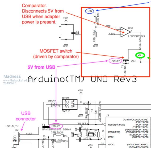 There are only 10 types of people in the world: those who understand binary, and those who don't. |
||||
| Warpspeed Guru Joined: 09/08/2007 Location: AustraliaPosts: 4406 |
[quote]I suppose we need to put a low Vf diode on the 5V supply to clamp it to no less than -0.5V[/quote] It may need to be the Shottky type to turn off fast enough. A sleepy old 1N4007 power diode may not be up to it. Cheers, Tony. |
||||
| poida Guru Joined: 02/02/2017 Location: AustraliaPosts: 1418 |
Of course, I have been mistaken. The manifest specified converter is NOT a flyback type, just a non-isolated Buck. But this 1V spike is present on it's output (of 15V) and it correlates perfectly with the observed 5V supply spike. Pink is 5V on nano2, Yellow is 15V output 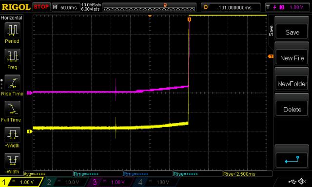 I thought I might use the tiny flyback converter as used in the Warpverter that RenewableMark is building. I have fitted one of the 15V units to the second nanoverter board. They can go to 15V. But they do not supply much current before the output drops. Only about 0.3A at 15V I only had 12V flyback units so I changed the feedback resistor to suit 15V. I found I needed 12.2K for 15V and 9.3K for 12V output. See below for modification. 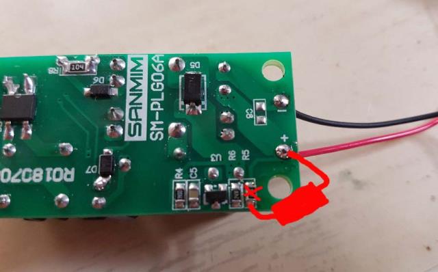 This is the power-on behavior of this converter. Light Blue is 50V supply, Yellow is 15V output. Note the vertical scale, 1V/div No negative glitch at all. And it takes about 300ms before output appears. 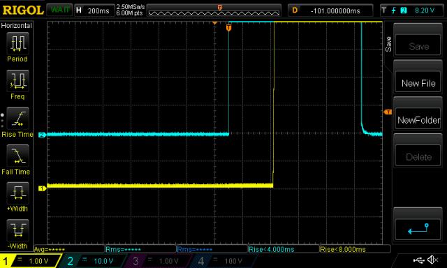 I think I will use these dc-dc converters. And it forces me to provide an external supply to power the fans. Oh, well. wronger than a phone book full of wrong phone numbers |
||||
| nickskethisniks Guru Joined: 17/10/2017 Location: BelgiumPosts: 458 |
I'm using a nano to manage my battery and solar limits. So mosfets between solar and battery and a main mosfet Array to switch all off. And my nano is powered by a buck converter, probably the same problem, I had to reprogram the nano. Now I now what the cause was or could be, I was first thinking a bad nano from china.. |
||||
Madness Guru Joined: 08/10/2011 Location: AustraliaPosts: 2498 |
Are you powering it with 5V or a higher voltage to the VIN? I made the mistake of using the 5V once and had a number of issues. Now all my Arduinos are powered by 12V to VIN and I never have a problem with any Nano losing its programme. There are only 10 types of people in the world: those who understand binary, and those who don't. |
||||
| BenandAmber Guru Joined: 16/02/2019 Location: United StatesPosts: 961 |
Madness how are you coming along on syncing I'm not trying to be an ass but what is the purpose of sinking to begin with With all the power that you create on a daily basis I couldn't imagine you ever needing it And if you ever did need it I know you know several other ways to do it And I'm just being honest I'm not being an ass I'm just curious By the way I to have a old Onan generator they are the best ever made if you ask me at least the best I've ever seen be warned i am good parrot but Dumber than a box of rocks |
||||
Madness Guru Joined: 08/10/2011 Location: AustraliaPosts: 2498 |
I am still waiting on parts to arrive. Although normally I have more than enough power there are times we get very heavy cloud cover for days and even weeks on end. It is not unknown to get a metre of rain here in a month, in those conditions my 14KW of panels can have a total of less 300 watts output in the middle of the day. Once at around noon there was around 40 watts being generated, over the next 2 hours we had over 200mm of rain. Previously I was using a Trace inverter, it could auto start my generator, sync to it, charge the battery and shut down the generator. Although it worked well the Trace inverter died of old age as it was made last century. I liked how it worked seamlessly with the generator and want to make my own inverter do the same. There are only 10 types of people in the world: those who understand binary, and those who don't. |
||||
| tinyt Guru Joined: 12/11/2017 Location: United StatesPosts: 438 |
poida et al, I apologize for the issue I created by selecting a poorly designed DC-DC converter. On another note, in a project that I used an Atmega1281 that saves configuration paramaters in eeprom, the eeprom sometimes gets corrupted. The flash does not get corrupted, only the eeprom. My last remedy was to 'park' the eeprom address to an un-used area after reading/writing the configuration parameters. This happens only in one customer installation (simulated aircraft cockpit). Maybe that simulated cockpit is too 'noisy' electrically. |
||||
renewableMark Guru Joined: 09/12/2017 Location: AustraliaPosts: 1678 |
Poida, might be an "out there" suggestion, but would it be worth a try of those little beads on the output of the dc/dc? If you solder it on with long legs that should fit in there nicely. Cheers Caveman Mark Off grid eastern Melb |
||||
mackoffgrid Guru Joined: 13/03/2017 Location: AustraliaPosts: 460 |
I presume the XL7017 buck controller was the offending Converter? |
||||
| Warpspeed Guru Joined: 09/08/2007 Location: AustraliaPosts: 4406 |
How about a 5v relay and running your fans off 230v ? Cheers, Tony. |
||||
| poida Guru Joined: 02/02/2017 Location: AustraliaPosts: 1418 |
More observations of the dc-dc supply and the two linear regulators. One thing I neglected to show was I am using a 7805 dc-dc module in place of the linear 7805. I chose to use this when the linear 7805 I first installed was getting stupid hot. And that was under nominal run conditions drawing maybe 100mA. This may have some contribution to the nano programming loss. So here I show a slow scroll of the application of 50V supply and removal after about 5 seconds. Let's see how the 5V supply behaves when I use the more efficient dc-dc type 7805 device. Yellow is 15V output from the 50-15V converter, Pink is 5V at the nano. 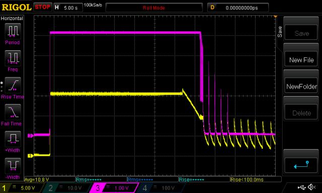 I zoom into the area when 15V drops below about 9V and we see the dc-dc type 7805 module oscillate it's output, at about a 33ms period. Probably going to cause problems with the nano(s) 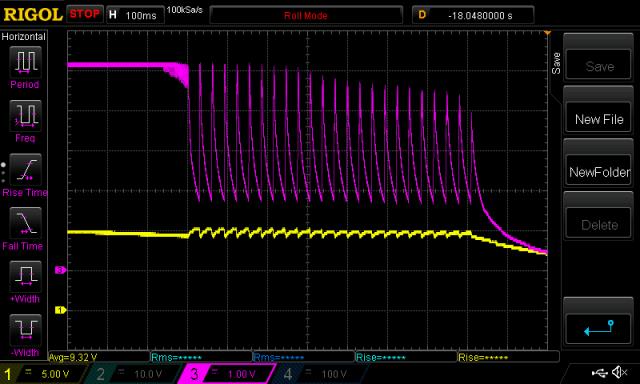 I immediately replaced that component with a linear 7805 and we now have none of that oscillation. 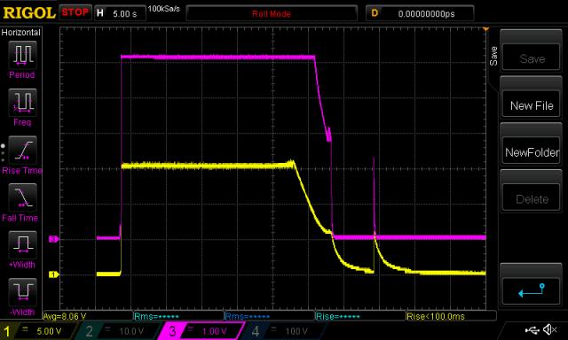 The negative pulse remains, due to it originating from the 50-15V converter. Have I created a waste of time for us all with my use of the dc-dc type 7805? wronger than a phone book full of wrong phone numbers |
||||
| Warpspeed Guru Joined: 09/08/2007 Location: AustraliaPosts: 4406 |
Its been rather like that over the last week or so here in Melbourne. Syncing to a wobbly old put put is going to be problematic..... Much better to rectify the output of your put put, and feed it either straight into the battery (and thus the inverter as dc) or into where the solar panels feed into your charge controller. No need to voltage regulate if you do it that way. Cheers, Tony. |
||||
| poida Guru Joined: 02/02/2017 Location: AustraliaPosts: 1418 |
so many questions: Wiseguy, I think I prefer to power these arduino designs via Vin, i.e 12V or something. I have found some situations where the computer USB connection causes reboot of the iMac, or puzzling ADC conversions, or what-not. My brute force solution is to use the android mobile phone and a USB dongle to calibrate/control the nanos. Totally isolated now. Tinyt, I will try a large ferrite bead. Probably no effect. I will also take the heatsink off it and look for product info for the controller. Maybe we get a clue from that. I have built the new inverter using separate XL7017 12V converters for the 2 fans. As long as everything using the same ground, they switch on and off fine when driven by the nanoverter's onboard FETs. And tinyt, it is still to be determined if the supply is causing the "need to reprogram". I suspect now it is the poor behavior of the dc-dc type 7805 regulator I used. And you will never need to apologize to me for anything. I have found that the nanoverter switches its self off sometimes, particularly when I touch the wire of the switch that leads directly to pin 11 (D8). At first I tried running the switch wires through a ferrite ring 3 times. This helps. I wanted a more solid result and so I put a 1uF electro across pin 11 and ground. This is better. Solid on/off switch response now. wronger than a phone book full of wrong phone numbers |
||||
Madness Guru Joined: 08/10/2011 Location: AustraliaPosts: 2498 |
Poida I am using the same dc to dc converters in the 12V version to run the Arduino and fans on my inverters. The 12V power supply is connected to the Nanos VIN, there is a 100uf electrolytic across the 12V, I have not done the analysis that you have, but I know it works without any hiccups and I can plug a computer in it anytime and reprogramme it without incident. There are only 10 types of people in the world: those who understand binary, and those who don't. |
||||