|

|
Forum Index : Electronics : OzInverter OzCntrl PCB rev12 Sept2017
| Author | Message | ||||
| Warpspeed Guru Joined: 09/08/2007 Location: AustraliaPosts: 4406 |
Thats around 1.66 watts per Kg (or a bit less if the core is larger). Sounds about right for maybe 1.2 Teslas from the curves I have here. But the steel in your cores may be of a much better grade, and the losses lower. So if you are actually up at around 1.5 Teslas, thats a pretty good result. That is the problem. If you chase up the data and some actual specifications of new core material you can buy, the numbers quoted vary rather a lot. It has to do with the actual silicon iron alloy, subsequent heat treatment, and thickness of the steel strip these cores are wound from. Its possible to make really high grade material for special purposes, but many manufacturers prefer to cut costs as a commercial decision. With unknown salvaged cores all we can do is guess and hope, or take some actual measurements. If you fire up an unknown core with say just ten turns, and run that up to say ten volts rms. You might measure something like five amps of idling power (50watts) at one volt per turn (or whatever). By tweaking the volts up and down it should be possible to plot a core loss versus volts per turn curve. I have never actually tried to do this at a low voltage and a few turns, but I have done something similar with an existing 230v winding and a variac. Measure the idling current at various applied voltages. The current will rise very steeply with increasing volts per turn. The difference between the no load current at say 200v and 230v and 260v on an existing 230v winding will give you a pretty good idea of the shape of the curve and the related losses for that particular core. With some fairly simple testing its possible to learn quite a lot, and plan accordingly. Cheers, Tony. |
||||
| Warpspeed Guru Joined: 09/08/2007 Location: AustraliaPosts: 4406 |
Here are some specifications for real top of the range high performance grain oriented steel core materials. For really large transformers losses are critical, because where there is a very large transformer mass, its much more difficult for the internal heat to escape. Where transformers can weigh many thousands of Kg, that is a lot of heat. http://www.aksteel.com/pdf/markets_products/electrical/AK%20CARLITE%20Lite%20042413.pdf If you scroll down to page 5 there is a blue and tan table of core loss for various thicknesses of material, and guaranteed core loss measured at 50Hz and 1.5 Kguass (=1.5 Teslas) and at 1.7 Kgauss (=1.7 Teslas). Our core material is usually 0.3mm thick equivalent to their M5 grade. Kilogauss are imperial US measurement, Teslas are Metric. From their figures for 0.3mm thick M5 material we get: 1.5 Teslas 0.44 watts per Lb or 0.968 watts per Kg 1.7 Teslas 0.63 watts per Lb or 1.386 watts per Kg That craps all over the Chinese stuff we are likely to get our hands on for free. So the figures I am using might be what to expect from cores we are likely to get for free. But there is vastly better core material available if you are prepared to pony up the cash. Shipping a large core half way around the world might be another problem. Another problem is often these cores are not ex stock but custom wound. No problem if you want to order fifty or a thousand toroidal cores. If you only want one, they may tell you to get lost, or charge a horrendous set up charge. Its not easy. Cheers, Tony. |
||||
Madness Guru Joined: 08/10/2011 Location: AustraliaPosts: 2498 |
From what you are saying there with quick read I am thinking the core from the Aero-sharps are doing quite well when you say 0.968 watts per KG for the ducks nuts stuff. I am consuming >50 Watts at idle say 40 is going into the transformer, it is not much more than 1 watt per KG. There are only 10 types of people in the world: those who understand binary, and those who don't. |
||||
| Warpspeed Guru Joined: 09/08/2007 Location: AustraliaPosts: 4406 |
Yes, those Aero-sharp toroids sound like an especially nice bit of kit. The only toroids I have messed with personally are the Inspire 1.5Kw ones which are probably fairly run of the mill typical. The old split C cores from AEM are about the same. The AEM curves seem to agree fairly closely with what my Inspire toroids do when tested. So the numbers and advice I have been giving is all based on that. AEM now supposedly produce a much "better" material, and their nice salesman says the magnetizing current is "considerably less" than their old cores they stopped making around ten years ago. But he never backed up that claim with any published curves or specifications. My own inverter does not use a single large toroidal core, so I have no future plans at this stage of buying anything, or winding my own monster transformer. Too many other projects on the go right now... Cheers, Tony. |
||||
renewableMark Guru Joined: 09/12/2017 Location: AustraliaPosts: 1678 |
sheeesh buying the parts is a pain. I am up to the 13v 1.3w zener diode BZX85C5V6 When I search for this it only comes up with 5.6v version. here Is 13v a typo? as the code matches a 5.6v version Cheers Caveman Mark Off grid eastern Melb |
||||
Madness Guru Joined: 08/10/2011 Location: AustraliaPosts: 2498 |
There is a 13V as well 5.6 and 6.5 on the latest control board you have. Having said that I have not found any 6.5V Zeners and use 6.2V instead. Going through and finding all those parts is a PITA, takes quite a few hours. I found the easiest way is to buy a pack like this. 13V works but I know Oztules is and I am using 18V instead. Buying resistors is similar, a pack like this will cover most of what you need for the control board. There are only 10 types of people in the world: those who understand binary, and those who don't. |
||||
renewableMark Guru Joined: 09/12/2017 Location: AustraliaPosts: 1678 |
Thanks again mate Jesus I wish someone came up with a kit!! Cheers Caveman Mark Off grid eastern Melb |
||||
| Clockmanfr Guru Joined: 23/10/2015 Location: FrancePosts: 429 |
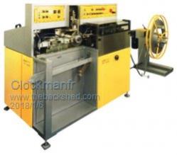
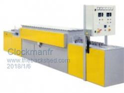
Here are my ferrite cores that go on one of the Primary cables, wrapped around a minimum of three times. The big OzInverter has these, but doubled up giving a 40mm thickness x 80mm x 80mm when assembled. A 75mm/2 flexible cable will easily go around the centre ferrite column 3 times. http://www.ebay.co.uk/itm/E8020-E80-Ferroxcube-3C90-E-EE-Ferrite-Cores-transformer-AL-5000-1set-/370683164776?hash=item5 64e703868 The 6kW OzInverter has these, just one set. 27mm thickness x 66mm x 64mm when assembled. Again wrap around at least 3 times, here I use 50mm/2 flexible cable. http://www.ebay.co.uk/itm/E6527-Ferroxcube-E65-E-EE-Ferrite-Cores-bobbin-Power-transformer-AL-8600-1set-/370597734866?ha sh=item564958a9d2 Super glue the core together, I use insulation tape to hold them tight while the super glue sets. Like this ....... Heres a photo for Tony..... the core winding machine, and heat furnace for 0.3mm silicone iron that has been doing my cores, but it has a max core thickness of 65mm so hence the need to stack the cores.   Everything is possible, just give me time. 3 HughP's 3.7m Wind T's (14 years). 5kW PV on 3 Trackers, (10 yrs). 21kW PV AC coupled SH GTI's. OzInverter created Grid. 1300ah 48v. |
||||
| Warpspeed Guru Joined: 09/08/2007 Location: AustraliaPosts: 4406 |
The situation of sourcing new toroids in Europe and America is probably a lot brighter than here in Australia. Here we have only one company AEM winding these toroids locally. Most of what we can scrounge from secondhand grid tie inverters very likely comes from China. The quality of the steel and its heat treatment might be a bit er, variable...... I don't know what AEM have on offer these days, but it may be quite a bit better than what they could supply in the past. Anyone that is really keen could contact their sales rep Mark Cushen and ask about sizes and magnetizing watts per Kg at different flux densities. E-mail address: MarkC@aemcores.com.au Cheers, Tony. |
||||
renewableMark Guru Joined: 09/12/2017 Location: AustraliaPosts: 1678 |
Thanks for the links on the ferrite cores Clockman. The local metal recylers lets people fish around their scrap bins, if I found one as big or bigger would that be fine? Madness, I like the idea of using the multiple strands for the primary, after pulling apart two 3kw aero sharps do you have enough wire left over to do it? Cheers Mark Cheers Caveman Mark Off grid eastern Melb |
||||
Madness Guru Joined: 08/10/2011 Location: AustraliaPosts: 2498 |
Yes plenty of wire on there, one trick with is when you get to the stage of winding the primary measure the length of 1 turn, multiply that by the turns and add at least 1500 mm to that. Cut your wires to double that length so have a loop at the end to hold it while twisting. By doing a double core the number of turns halves from what a single core uses and the length of each turn is quite a bit less than on a single, so this leaves quite a bit of wire spare when completed. If you search through the forums you will find people have used a number of different ferrite cores, my inverter is running ATM with a 100mm ferrite ring. It does not hurt to play around with different cores and number of turns. You can measure the current drawn by the inverter with a DC clamp meter(expensive) or a shunt (if you get a shunt you can wire it permanently if this is the case get one that is at least 200A). You can measure the idle current and check the wave form, if the choke is not the right value you will get distortion at zero crossing on the wave form. There are only 10 types of people in the world: those who understand binary, and those who don't. |
||||
renewableMark Guru Joined: 09/12/2017 Location: AustraliaPosts: 1678 |
Ripper, thanks again, seems like it's a better idea to buy the ferrite in Clockmans link as it's been tried and tested. Reckon I'm better off not introducing variables. Cheers Caveman Mark Off grid eastern Melb |
||||
Madness Guru Joined: 08/10/2011 Location: AustraliaPosts: 2498 |
You can buy the same E65 core from RS Components here in Australia and it will be delivered in a few days and price is almost the same. Don"t forget the Former for it also. There are only 10 types of people in the world: those who understand binary, and those who don't. |
||||
renewableMark Guru Joined: 09/12/2017 Location: AustraliaPosts: 1678 |
Thanks mate, do you need the former? The wire only goes around 3 times, should be easy doing that. Or is it to protect the wire from sharp edges? I unwound two lengths of wire from the ferrite so far today, that's fun! Cheers Caveman Mark Off grid eastern Melb |
||||
| Tinker Guru Joined: 07/11/2007 Location: AustraliaPosts: 1904 |
I just bought a core from RS, has not yet arrived. Its the alternative on the bottom of mad's link, my search did not find the cheaper one mad uses. The bobbin (former) is nearly as expensive as the core, you don't really need it (and you get more wire room without it). But beware, the corners are sharp and require tape. Some suggest super gluing the cores together, this is a one way trip and I do not like it. Its a lot easier if you can hammer your wire around a dummy core made of hardwood or something and then insert the core halves over it, rather than trying to wrestle that stiff wire through the core opening and break the fragile thing in the process. Besides, I found my core was a lot quieter after I stuck one layer of clapton tape to each mating surface, this creates a tiny air gap. I also used 3.2x4.5mm rectangular enameled copper wire rather than that unwieldy cable for this choke, 4 in hand gives me 57.6mm sq and I very much doubt you could fit any insulated cable with that section on this core. If you are thinking to use the salvaged toroid wire, 1.8mm dia. = 2.5mm sq so you need to find out how many you can twist together and end up thinner than 11mm diameter, it won't be anywhere near the cross section I got though  . . As for assembling, you can see it on a picture of my double stack inverter (building an inverter from scratch). I made 10mm plywood clamping plates and two coach bolts hold it firmly together. This lets me torque it up until its quiet with a load on the inverter. You also might want to practise first with a short length of twisted 1.8mm wires to get the technique right. Ideally you want a smooth outer surface with no cross overs so it tightens easy around the core. Keep in mind that wire is already work hardened from your straightening process and any bending makes it stiffer still. With that in mind do plan your winding technique around the toroid beforehand, it won't do trying to unwind and start again with that stiff wire bundle. I suggest you coil your length of twisted wire carefully, about 900mm diameter, tie the start with masking tape to keep it in a circle. Make a toroid winding table (look it up in posts or ask and I'll take another picture for you) and then pre-load that 900mm dia coil around the toroid. I found it easiest if the wire comes *up* the hole, this makes it easy to wrap it towards you as you hammer it slightly with a plastic faced hammer or similar. tighten the loop while you rotate the large coil, making sure the bundle loops do not cross over as you go. This becomes a *lot* easier with practise  . I just wound my third toroid and it was a breeze compared to the first. . I just wound my third toroid and it was a breeze compared to the first.Klaus |
||||
Madness Guru Joined: 08/10/2011 Location: AustraliaPosts: 2498 |
I see Clockmans does not have the former and as Tinker says it is not essential. I have glued mine together, even though it is a one-way trip there is no need to do a u-turn. If you are using fine strand wire it is easy to wind when assembled but anything stiffer need to be wound on some sort of form before assembly. If the 2 halves are not stuck together very firmly it will vibrate and sound like it possessed, super glue takes care of it. There are only 10 types of people in the world: those who understand binary, and those who don't. |
||||
renewableMark Guru Joined: 09/12/2017 Location: AustraliaPosts: 1678 |
Outstanding! I still can't believe how helpful all you guys are. Cheers Caveman Mark Off grid eastern Melb |
||||
| Warpspeed Guru Joined: 09/08/2007 Location: AustraliaPosts: 4406 |
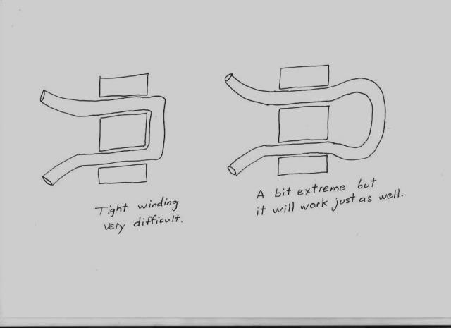
When winding very heavy cable through those ferrite E cores, its only necessary for the wires to pass through the slots the required number of times. There is no requirement to have a very "tight" winding, as its very difficult to make very tight right angle bends around the rectangular centre of the core. So don't worry about having big loops sticking out on either side, it has absolutely no effect on the inductance. The length of wire will obviously be very slightly more, but the difference will be negligible in the great scheme of things.  Cheers, Tony. |
||||
| Mulver Senior Member Joined: 27/02/2017 Location: AustraliaPosts: 160 |
Any suggestions for reasonable priced multimeters? Good enough for building inverters an testing solar panels? Maybe something like this? Fluke 15B I have a good current clamp meter that only does AC voltage and my other meter is crap. |
||||
renewableMark Guru Joined: 09/12/2017 Location: AustraliaPosts: 1678 |
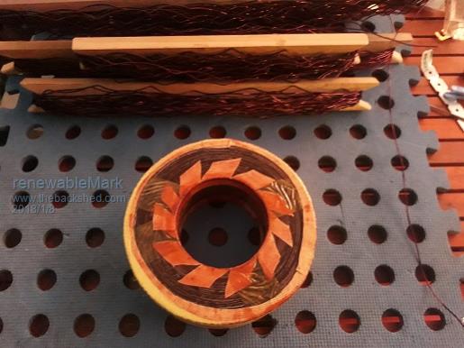
I got a clamp meter at supercheap auto that does DC, seems accurate enough, I think it was $70 or so.  I got my torroid all apart today, sheesh got sore muscles I didn't know I had. Warpspeed, thanks mate, I didn't know that. Cheers Caveman Mark Off grid eastern Melb |
||||