
|

|
Forum Index : Electronics : Inverter PCB’s
| Author | Message | ||||
| poida Guru Joined: 02/02/2017 Location: AustraliaPosts: 1419 |
Got my power boards. They look great. Thanks for your work on this. wronger than a phone book full of wrong phone numbers |
||||
Madness Guru Joined: 08/10/2011 Location: AustraliaPosts: 2498 |
The post box I put them in included Melbourne on the list that would get it the next day if posted by 5PM, it was 2:30 when I posted them. I know at least 3 people have got them today. No problem Poida, I look forward to seeing how you guys go with syncing an inverter for charging. There are only 10 types of people in the world: those who understand binary, and those who don't. |
||||
renewableMark Guru Joined: 09/12/2017 Location: AustraliaPosts: 1678 |
Aus post are completely useless, they'll turn up middle of next week and if you question them the reply will be something like "yeah nah, yooz got it didn't yuz?" Many times overnight bags have not come overnight, I'm not in the least bit surprised. Not your fault Mad.  Cheers Caveman Mark Off grid eastern Melb |
||||
| Phil23 Guru Joined: 27/03/2016 Location: AustraliaPosts: 1664 |
From what I've read these could serve as DC switches as mentioned else where. Just wondering what I need to start getting on had if I want to build 2 "Switches" for swapping the Arrays on my PV2 input. Been starting a list & would appreciate feedback. Will have some of the basic stuff on hand, or just down the road at Jaycar. Mosfets Insulators TIP35C Power Supply Arduino Nano ADS1115 I'm willing to try & get my head around Arduino & out of the sand, but would also like to try running the board of a MicroMite if I can come up with an adaptor. Phil. |
||||
| Hoges57 Newbie Joined: 11/05/2018 Location: AustraliaPosts: 1 |
Hi Madness, A newbe on the forum, just enquiring if any 24 fet boards and controller boards available? Just starting out, 3 kw of panels and a number of GTI's waiting in the shed just need a stable inverter to fire up a mini grid. Thanks, Gary |
||||
Madness Guru Joined: 08/10/2011 Location: AustraliaPosts: 2498 |
Hi Phil, I have a version of this operating now for some time but am adding more functions for the next batch of PCBs. ADS1115 is only needed if you are wanting to monitor battery current, otherwise, you can leave it out and jumper the battery voltage to one of the analogue inputs. The Isolated PSU used on the PCB above is this one with a 6k8 smd resistor across a 2k4 (R6). You will also need A3120 Isolated Driver ICs. Sorry can you give details again as to what you are switching and under what conditions you want to switch it and is all this going to VIA GTI's? There are only 10 types of people in the world: those who understand binary, and those who don't. |
||||
Madness Guru Joined: 08/10/2011 Location: AustraliaPosts: 2498 |
Hi Hoges57, Yes I have PCBs available however there will be a slight increase in price as the initial group of people committed and paid in advance to get the numbers up. 24FET Power Boards $35 Control Boards $15 Fan boards $8 (not needed with control board above) 1 or 2 sets of PCBs will cost $15 for express post PM me if you want to go ahead. There are only 10 types of people in the world: those who understand binary, and those who don't. |
||||
| Phil23 Guru Joined: 27/03/2016 Location: AustraliaPosts: 1664 |
I have a 3kW String on PV1 & want to be able to choose one of 2 other strings to connect to PV2, initially just based on time of day. Might get more elaborate down the track, but for the past week I've just been pulling plugs at around 2:00pm.... Wired up a couple of spare Iso last night with a common output, so now have a manual "Click-Click" transfer, but ultimately I'd like it automated. Noticed somewhere you had a post with Master/Slave PCB's, but whatever the requirement I'll jump for whatever's appropriate. Phil. Edit.. It's a hybrid I'm running, but have the 3 strings now & only 2 PV inputs. Also 1 string is only 6 panels, so significantly different in it's Voc. |
||||
Madness Guru Joined: 08/10/2011 Location: AustraliaPosts: 2498 |
I have changed my plan regarding the slave PCB. What I plan to do now is use the same PCB without some components and different software. The master will transmit the PWM value via RS485 and the slave can be up to 1200 m away. The slave will then just put out the amount of power required. There are only 10 types of people in the world: those who understand binary, and those who don't. |
||||
Madness Guru Joined: 08/10/2011 Location: AustraliaPosts: 2498 |
Almost ready to run the control board, just need to clean the flux off and check it. Bottom photo show where the I am mounting the fan MOSFETs and TIP35c's so the can be screwed to the power board heatsink. 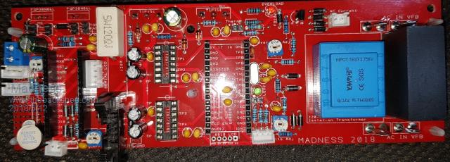 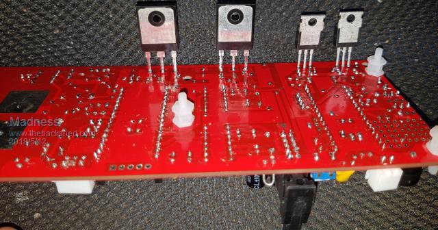 There are only 10 types of people in the world: those who understand binary, and those who don't. |
||||
renewableMark Guru Joined: 09/12/2017 Location: AustraliaPosts: 1678 |
Good work Mad, I was playing around with the nano today and changed some numbers to make the flash go longer/shorter, and gap longer/shorter. Anyway at least I know it's loaded properly and I can upload codes. It's surprisingly easy to change values if the basic code is already there. This is the flashing upload I did and changed. Quite a versatile little thing really, with lots of sensors available lots of projects could be done. Cheers Caveman Mark Off grid eastern Melb |
||||
Madness Guru Joined: 08/10/2011 Location: AustraliaPosts: 2498 |
Good to see you are getting into it Mark, yes the Arduino is so easy to do so much. You probably can see now how it I did my first sketch to get my SWHS working. There are only 10 types of people in the world: those who understand binary, and those who don't. |
||||
renewableMark Guru Joined: 09/12/2017 Location: AustraliaPosts: 1678 |
Yeah I showed my wife how I could change it's flashing with just a few clicks, her reply was " so you find that interesting??" Well I can see potential for it's uses and ease of changing what makes it work and at what values, temp, light, volts all sorts of things. Quite amazing and easy to work with really. One little tip for anyone not familiar with them setting it up, when you first plug it in to the USB it will have a little notification window appear bottom right telling you it's installing device. It will tell you which com port that is. You'll need that when uploading. Cheers Caveman Mark Off grid eastern Melb |
||||
Madness Guru Joined: 08/10/2011 Location: AustraliaPosts: 2498 |
Logic and women are like oil and water. I am working on the sketch for the control board ATM, so at this stage, all you will really need to know is how to open a sketch and upload it to the Nano. But learning more like you are will open more doors for you. There are only 10 types of people in the world: those who understand binary, and those who don't. |
||||
Madness Guru Joined: 08/10/2011 Location: AustraliaPosts: 2498 |
I have effed up a little, couple small errors on the control board. You will need to cut the 2 tracks as per below and connect the 4u7 cap to ground, replace the left 1K resistor with a wire link. 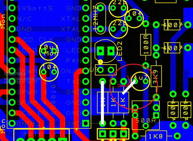 The 5V is connected to the wrong spot for the temperature sensors, so the track needs cutting and a link soldered in as shown. 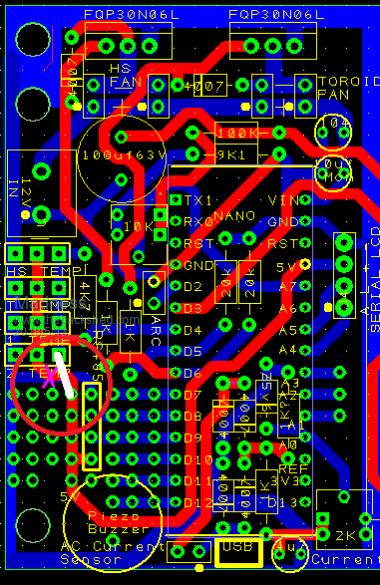 Also R44 and R46 on the power board are shown as 10 ohm on the silkscreen, they should be 5K1 ohm. 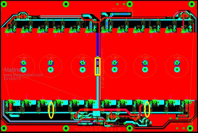 Apart from that seems to be all good I have had the Control Board and Power Board running but just with 4 FETs and no caps so far. Unfortunately, I have had other things taking up my time ATM. There are only 10 types of people in the world: those who understand binary, and those who don't. |
||||
| Tinker Guru Joined: 07/11/2007 Location: AustraliaPosts: 1904 |
While you are modifying your control board, may I suggest you solder a 10K resistor from pin 6, EG1810 to ground. Its a safety device that lets you unplug the power switch (accidentally  ) while the unit is still powered up and nothing happens. No instability blow ups ) while the unit is still powered up and nothing happens. No instability blow ups  . .Klaus |
||||
Madness Guru Joined: 08/10/2011 Location: AustraliaPosts: 2498 |
Sounds like you are speaking from experience Klaus? So like this. 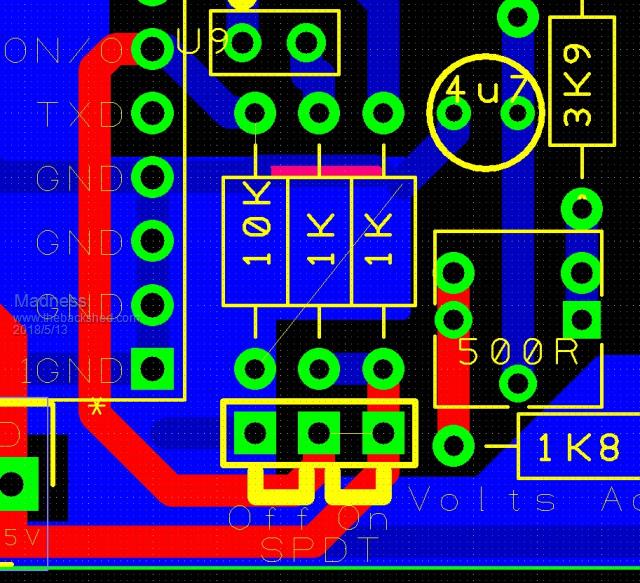 There are only 10 types of people in the world: those who understand binary, and those who don't. |
||||
| yahoo2 Guru Joined: 05/04/2011 Location: AustraliaPosts: 1166 |
Dammit! we were looking right at it almost a month ago and still missed it! I knew something wasn't right in there, I was just too slow to figure out what. I'm confused, no wait... maybe I'm not... |
||||
Madness Guru Joined: 08/10/2011 Location: AustraliaPosts: 2498 |
It works but does not turn off and the LED did not work as it was. I should have look at it more seriously when you raised the question Yahoo. Fortunately, it is not hard to fix. There are only 10 types of people in the world: those who understand binary, and those who don't. |
||||
renewableMark Guru Joined: 09/12/2017 Location: AustraliaPosts: 1678 |
could you just cut the link to led2 above the solder joint of the 1k resistor? Cheers Caveman Mark Off grid eastern Melb |
||||