|

|
Forum Index : Microcontroller and PC projects : PicoMite V6.00.01 release candidates - please test thoroughly
| Author | Message | ||||
| ville56 Senior Member Joined: 08/06/2022 Location: AustriaPosts: 119 |
Some results .... if the pin is set as normal DOUT, than everything works normal, pin can bet set low and high and also supplies current. If the pin is used for DS18B20, then even 39k already shift the level up to some degree. So for some reason the pin has a very high output restistance and/or can sink almost no current. The change seem to have happened from V6.00.00 RC15 to V6.00.00 RC17. 73 de OE1HGA, Gerald |
||||
| Mixtel90 Guru Joined: 05/10/2019 Location: United KingdomPosts: 6909 |
Have you tried a different pin? Is it localised to GP14 or the GP14/15 pair for example? Mick Zilog Inside! nascom.info for Nascom & Gemini Preliminary MMBasic docs & my PCB designs |
||||
| ville56 Senior Member Joined: 08/06/2022 Location: AustriaPosts: 119 |
tried also GP1, same result. It seems to be related with the pins usage for DS18B22. 73 de OE1HGA, Gerald |
||||
| Mixtel90 Guru Joined: 05/10/2019 Location: United KingdomPosts: 6909 |
Have you measured its load current? Mick Zilog Inside! nascom.info for Nascom & Gemini Preliminary MMBasic docs & my PCB designs |
||||
| ville56 Senior Member Joined: 08/06/2022 Location: AustriaPosts: 119 |
if the pin is in low state and R is 4k7, then the pin current is 36 uA and the pin voltage rises to 1,6 V. The resistor is connected to 3,3V. Measurements taken when in DS18B22 state. Things are different when set to output via setpin gpx, dout. Edited 2024-12-09 01:13 by ville56 73 de OE1HGA, Gerald |
||||
| Mixtel90 Guru Joined: 05/10/2019 Location: United KingdomPosts: 6909 |
Silly question I know, but I assume you have 3V3 on the supply pin of the sensor? Mick Zilog Inside! nascom.info for Nascom & Gemini Preliminary MMBasic docs & my PCB designs |
||||
| ville56 Senior Member Joined: 08/06/2022 Location: AustriaPosts: 119 |
yes, 3.2 V to be exact. The current varies a bit, as do the pin voltage. Now i did read 2,3V and 46 uA. TBH i do not know what the Ri of my Ammeter is, but i think it should be already considered in the measurement to explain the numbers. IMHO they do not quite follow Ohms law .... 73 de OE1HGA, Gerald |
||||
| Mixtel90 Guru Joined: 05/10/2019 Location: United KingdomPosts: 6909 |
Won't make much difference at that current. The chip varies it's current depending on what it's doing anyway. The data pin of the chip is only sinking the current through the 4K7, as is the Pico. That's only 0.7mA. The Pico doesn't see the current drawn by the chip. This is strange. Have you tried putting an LED and resistor on the pin and seeing if you can drive it both ways to test pull-up and pull-down using PIN() commands? Mick Zilog Inside! nascom.info for Nascom & Gemini Preliminary MMBasic docs & my PCB designs |
||||
| ville56 Senior Member Joined: 08/06/2022 Location: AustriaPosts: 119 |
Using PIN() means to enable it as output with SETPIN first. Then things are as expected. But setting the pin with TEMPR STRART gpx,2 changes the behaviour. Well, it could of course be that i just measure the pulldown resistor of the then input section of the pin. That would explain the nonlinear behaviour. I have to think again how to measure this strange effekt. I'll try to make a picture with the scope that is telling more. 73 de OE1HGA, Gerald |
||||
| Mixtel90 Guru Joined: 05/10/2019 Location: United KingdomPosts: 6909 |
It's interesting as the Pico can't have open drain signals (it's a totem pole output). I'm guessing that in the code the output is set low then the mode register switches it between input (in which case the external resistor will pull it high) or output (in which case the output will go low as expected). If the output can be driven low normally then there's no reason why it shouldn't sink 0.7mA when used as a 1-wire driver. There's no pull-down resistor involved when using it in this mode, it's a turned on MOSFET. The pull-up MOSFET will be turned off as the output is set low. The input resistance will be very high. Probably over 100K. With a 4K7 pullup you should probably see very close to 3V3 but you'll need a pretty high impedance scope probe that isn't drawing current through the 4K7 to confuse the issue. :) Beyond that I don't know. If these sensors have worked on one version of MMBasic and not on another when using the same module then it has to be a firmware thing. I note though that the 18B22 is not entirely the same as the 18B20 (which is now out of production). Mick Zilog Inside! nascom.info for Nascom & Gemini Preliminary MMBasic docs & my PCB designs |
||||
| ville56 Senior Member Joined: 08/06/2022 Location: AustriaPosts: 119 |
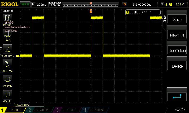
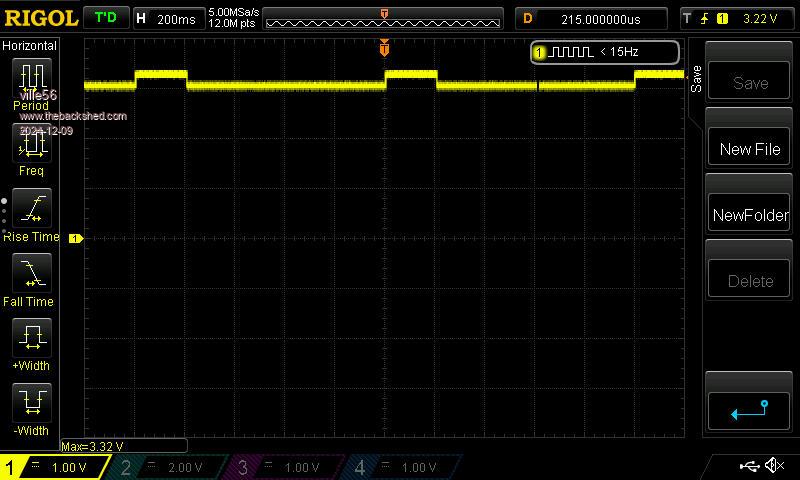
2 scope images: 1) signal at the DS18B20 without pullup resistor (data are at the low/high transition but resolution is too low to see them)  2) same signal with pullup 4k7 attached  my conclusion: the pico does not properly pull the pin to low with 4k7 pullup to start the conversion because the output is not correctly set since at least V6.00.00 RC17. 73 de OE1HGA, Gerald |
||||
| Mixtel90 Guru Joined: 05/10/2019 Location: United KingdomPosts: 6909 |
It looks like that. Perhaps the output wasn't set to low before the in/out mode switching? That would almost certainly be in the firmware. Mick Zilog Inside! nascom.info for Nascom & Gemini Preliminary MMBasic docs & my PCB designs |
||||
| Volhout Guru Joined: 05/03/2018 Location: NetherlandsPosts: 4345 |
Hi, To me it looks like it is switching between weak pullup and weak pulldown. Where it should be between weak pullup and output low. Maybe the wrong bit is set in the data direction register for the TEMPR driver. This could be a result of Peters experiments with the 2350 GPIO problem. Volhout Edited 2024-12-09 05:51 by Volhout PicomiteVGA PETSCII ROBOTS |
||||
| Mixtel90 Guru Joined: 05/10/2019 Location: United KingdomPosts: 6909 |
The pullup is 4K7 external. I make it about 70.5K pulldown when it should be really low.. Mick Zilog Inside! nascom.info for Nascom & Gemini Preliminary MMBasic docs & my PCB designs |
||||
| ville56 Senior Member Joined: 08/06/2022 Location: AustriaPosts: 119 |
Just tested with V6.00.00 RC16 and it is working ok. So the change must have happened from RC16 to RC17. 73 de OE1HGA, Gerald |
||||
| Mixtel90 Guru Joined: 05/10/2019 Location: United KingdomPosts: 6909 |
Ah..... there lies a challenge for Peter. :) Mick Zilog Inside! nascom.info for Nascom & Gemini Preliminary MMBasic docs & my PCB designs |
||||
| phil99 Guru Joined: 11/02/2018 Location: AustraliaPosts: 2181 |
Yes, on my previous RC5 test I forgot to install a pullup resistor. Re-tested with pullup and with V6.00.00 RC16 and it is working but not with V6.00.01 RC5. |
||||
| Volhout Guru Joined: 05/03/2018 Location: NetherlandsPosts: 4345 |
Even basic things that worked for years have stopped working.. Honestly, this was my worst fear. tons of bugs That is why I hoped the 5.09.00RC5 was frozen for 2040. And 2350 was the new platform for CMM1.5 Peter must be tired of all this endless bug hunting, making common code for such different platforms. Volhout PicomiteVGA PETSCII ROBOTS |
||||
| Mixtel90 Guru Joined: 05/10/2019 Location: United KingdomPosts: 6909 |
I suspect that most of the problems will be because of changes to the SDK. There isn't a lot of choice in that as it *will* be upgraded by Raspberry Pi whether you like it or not. :) Mick Zilog Inside! nascom.info for Nascom & Gemini Preliminary MMBasic docs & my PCB designs |
||||
| PhenixRising Guru Joined: 07/11/2023 Location: United KingdomPosts: 920 |
No kidding  |
||||