| |
  Page 10 of 13 Page 10 of 13   |
| Author |
Message |
wiseguy

Guru

Joined: 21/06/2018
Location: AustraliaPosts: 1156 |
| Posted: 10:59pm 16 Aug 2024 |
 Copy link to clipboard Copy link to clipboard |
 Print this post |
|
You are now on the same page I am on, re your understanding of how and why it is intended to function. After multiple starts using the second stage switching PCB I eventually saw ~ 60A surges of start current. I used household mains as stage 1 but have to admit I was a bit cautious and initially crept up to 240V with a Variac.
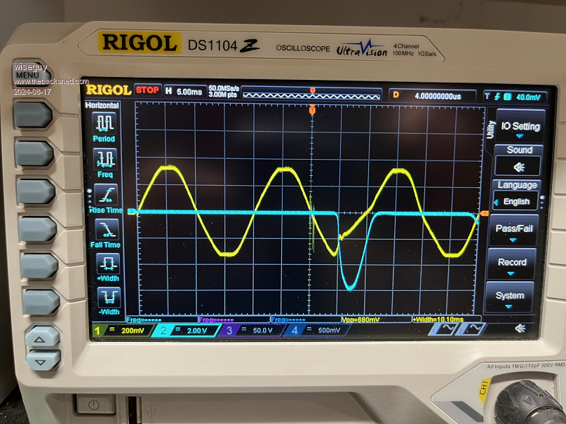
Then I got braver and just used house mains direct. The 60A surges at switch on were because all the relatively rapid start stops to find a start surge had eventually heated up the NTC thermistors so they were almost a piece of wire. You can see the house mains collapsing at the Toroid input in the pictures for the 60A event. The long run of mains supply cable from my workshop back to the house switchboard and the extension lead I was also using obviously added some impedance, which was good, I didnt even trip the breaker once.
I cheated a bit though, each start up of the NTC limiting stage was looking for the start surge so when the CRO triggered I immediately removed the 12V, cancelling the on board 2 & 10 second timers, reprimed the CRO and applied the 12V for another cycle, 2-3 seconds between each successive multiple start ups, that was why the thermistors eventually heated up to become a very low R. Ok some short pauses when I captured something worth showing I took a quick screen shot and then carried on. In retrospect the little 6A start relay handled the 60A surges very well  . .
If we use the 60A single cycle surge current as a starting figure, with around a 1-8 turns ratio between primary and secondary that equates to at least 480A of primary current on stage 1 but remember there is less impedance in the primary than my equivalent mains side testing so no doubt higher than this figure, the NTCs are very important. We always knew/suspected this to be the case so the tests are just emphasising what would really happen without mitigation to control the second stage start up.
Having time now to digest the results, a 1 second timer for stage 2 NTC start up should be ample and NTC values of around 20-25R each should limit the primary current to worst case single cycle of ~ 40-50A, piece of cake! Of course switching the stage 2 to manual before switching the inverter to "run" allows a gentle soft start simultaneously of both toroids.
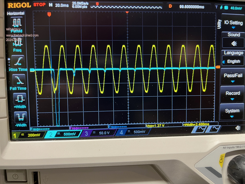
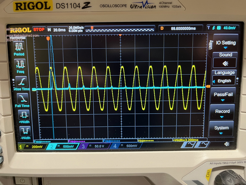
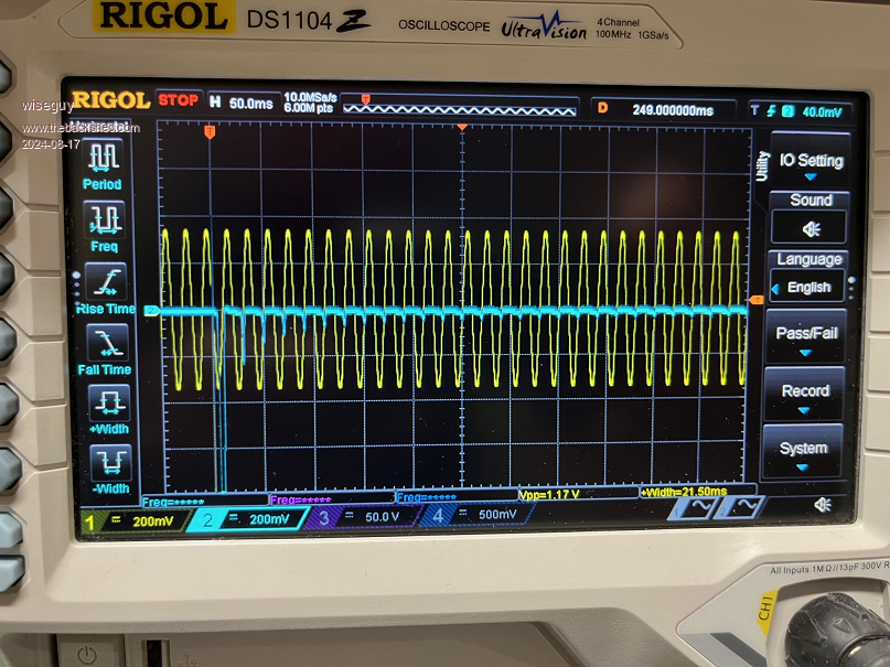
In the following screen shots the yellow mains had a 1000-1 divider so 200mV = 200V.
The blue trace when set for 1V = 10A/div, 0.5V = 5A div and 200mV = 2A/div
First a 60A surge
Now a ~25A surge showing reducing currents each cycle
And a positive cycle capture for completeness
And finally a longer capture of reducing current amplitudes
Edited 2024-08-17 09:06 by wiseguy
If at first you dont succeed, I suggest you avoid sky diving....
Cheers Mike |
| |
wiseguy

Guru

Joined: 21/06/2018
Location: AustraliaPosts: 1156 |
| Posted: 11:29pm 16 Aug 2024 |
 Copy link to clipboard Copy link to clipboard |
 Print this post |
|
After looking at the pictures for a while the large current peaks are always captured at the peak of the mains. Sure there are other smaller surge events but the significant ones are 10-20 times larger than the smaller ones. This appears to mean that if the start up was synced to a zero cross then these huge start up surges could be avoided anyway. I know KeepIS and myself (maybe others too) had considered using a solid start relay (zero cross type) that was then bypassed by a relay a short time later could also work.
I also think that one day when so inspired I will experiment with a way of applying some DC to the second stage toroid briefly to bias it in one known direction and then ensure the first start cycle is in the opposite direction so it will begin by pulling it out of saturation rather than adding to it.
KeepIS the second stage boards you are going to use I apologise for the 30A relay footprint I could not find a complete mechanical drawing so merging an outline drawing and the footprint did not work well and it has slight rotation moment to the silk screen, but is now fixed.
Also the Pin 1s for the opto cables are the pins closest to each other and both next to C5
If at first you dont succeed, I suggest you avoid sky diving....
Cheers Mike |
| |
KeepIS

Guru

Joined: 13/10/2014
Location: AustraliaPosts: 1679 |
| Posted: 01:28am 17 Aug 2024 |
 Copy link to clipboard Copy link to clipboard |
 Print this post |
|
Really great information, nice to confirm that it works as intended.
No problem with that 30A relay, I had a few in one of my parts bin, I didn't even notice the slight rotation of the 12v coil pins, I had to lift the relay out "not soldered in yet" to see that slight angle on the two pins.
Back to wiring up the control panel and installing sensors.
I going to get the dual inverter working as a single stage unit first, then I can take the current inverter off line and take the Toroid and chokes across to the new inverter and minimize the time on mains power.
_
It's all too hard.
Mike. |
| |
wiseguy

Guru

Joined: 21/06/2018
Location: AustraliaPosts: 1156 |
| Posted: 02:21am 17 Aug 2024 |
 Copy link to clipboard Copy link to clipboard |
 Print this post |
|
I know I mentioned it before but KeepIS will be ready for real world testing of his two stage inverter a fair way before I will be ready to test mine. There is something that would be nice to know. That is, applying increasing loads of 1 or 2KW up to at least 6+kW and note the input current at each step. Then redo the tests with both transformers connected to see if there is a point where 2 transformers become more efficient than just the 1.
If there is a point at say 4kW when two toroids become more efficient than 1, then the point at which it starts to become more efficient would be the output current level to switch in the second stage. It is possible that this efficiency point might be right at the top end of - or past the expected toroids throughput, in which case that would be the point to switch in the second unit.
There will obviously be some other factors such as Toroid heat which might cause us to re-think and modify these levels lower when we have some real world data to work with.
Edited 2024-08-17 12:21 by wiseguy
If at first you dont succeed, I suggest you avoid sky diving....
Cheers Mike |
| |
KeepIS

Guru

Joined: 13/10/2014
Location: AustraliaPosts: 1679 |
| Posted: 02:31am 17 Aug 2024 |
 Copy link to clipboard Copy link to clipboard |
 Print this post |
|
I'll will certainly try my best to test as much as I can once I get it running. I have a feeling that I'll be running in dual mode most of the time, but I love the option of lower power under extended low solar conditions when just powering the essential loads.

It's all too hard.
Mike. |
| |
wiseguy

Guru

Joined: 21/06/2018
Location: AustraliaPosts: 1156 |
| Posted: 03:23am 21 Aug 2024 |
 Copy link to clipboard Copy link to clipboard |
 Print this post |
|
I will be placing another much smaller order shortly for some sets of inverter PCBs for someone in Portugal and another in France. If anyone else (hopefully in Australia.....) is interested in a set or sets of boards, now is the time to tell me and they can be added to the order. The pricing will be similar but no doubt slightly higher, (I estimate just a few dollars) due to the high freight costs and smaller quantities being ordered.
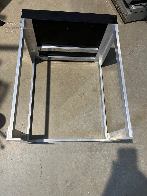
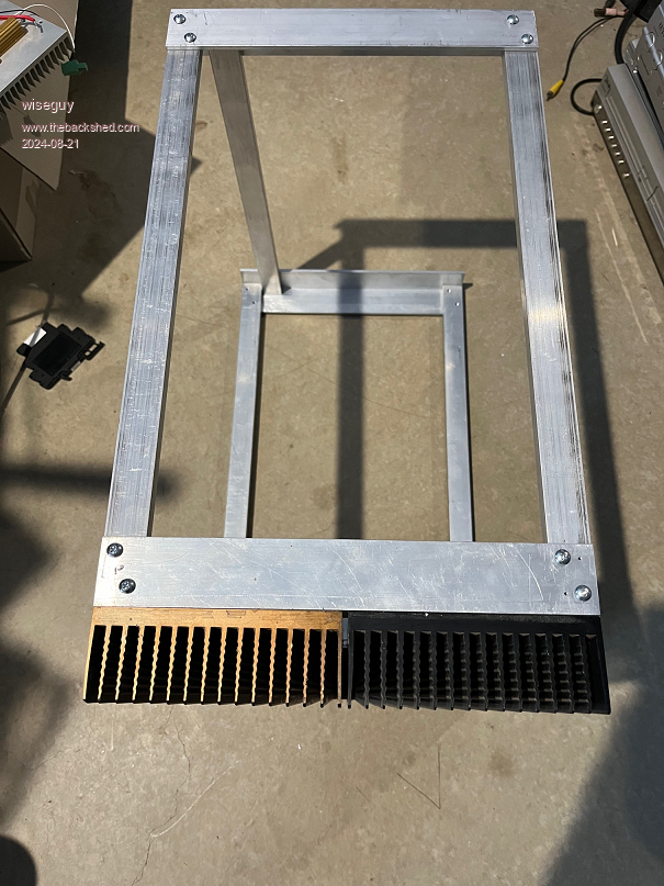
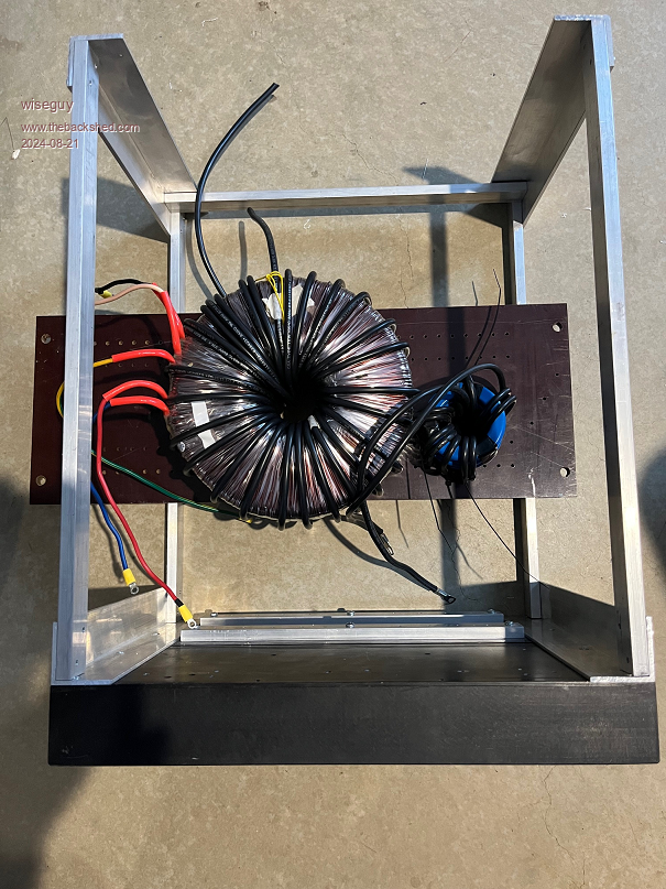
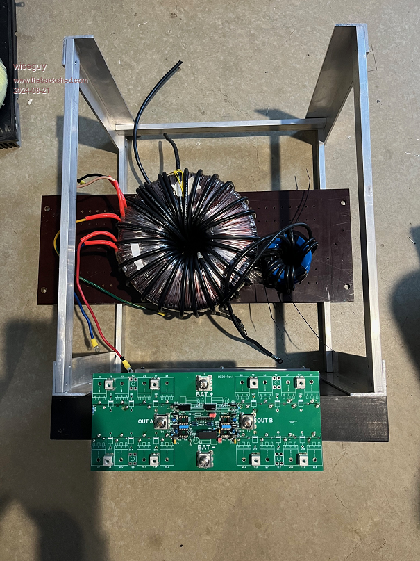
I am busy building up my own 2 stage inverter, it is using 2 Aerosharp heatsink modules and lots of 10mm x 25mm Aluminium lengths and 4mm x 4mm aluminium angles etc. So far I have the frame built, I have also wound the primary for one 3.5kW Toroid, another still to do, I used some 10mmsquare cable I had to hand (time will tell) and I decided to add a 17T overwind to the 195T secondary to match the other 212T winding for lowest secondary losses - & so much more still to do.....
It will be a lot smaller and using less combustible material than KeepIS (who has lots of access to wood and woodworking tools) but due to the open frame construction I am using should still be really easy to work on once covers are removed. I do see the sense though in using wood screws as an alternative to my method, (I have lost count of all the threads cut so far) and plenty more still to do, the novelty wore off after about the third thread cut!
Basic Frame dimensions are ~ 500L x 400W x 300H and I expect it to house both stages, 2 x toroids (second on top of first), 2 x chokes etc, tight yes, bloody heavy, but I think do-able.
Basic Frame Top
Basic Frame Side
Mock up (fibre board to be cut to size)
Against Power PCB for size comparison
Edited 2024-08-21 13:33 by wiseguy
If at first you dont succeed, I suggest you avoid sky diving....
Cheers Mike |
| |
KeepIS

Guru

Joined: 13/10/2014
Location: AustraliaPosts: 1679 |
| Posted: 06:39am 21 Aug 2024 |
 Copy link to clipboard Copy link to clipboard |
 Print this post |
|
Nice to see that coming together, heatsinks appear to be the same size as the two I'm using 
Fine on the timber, countless years of making "big" Valve stage and guitar amplifiers gives me confidence to go with what I know and am able to work with.
I'm still a few days off getting mine going as life's little interruptions keep happening, just when I don't want them 
It's all too hard.
Mike. |
| |
KeepIS

Guru

Joined: 13/10/2014
Location: AustraliaPosts: 1679 |
| Posted: 06:47am 21 Aug 2024 |
 Copy link to clipboard Copy link to clipboard |
 Print this post |
|
Wrong thread - sigh 
Edited 2024-08-21 18:16 by KeepIS
It's all too hard.
Mike. |
| |
wiseguy

Guru

Joined: 21/06/2018
Location: AustraliaPosts: 1156 |
| Posted: 08:21am 21 Aug 2024 |
 Copy link to clipboard Copy link to clipboard |
 Print this post |
|
Very neat, I've just packaged mine up to send to you..... Crap where did it go ? lol (I nearly posted my construction pics on your thread - easy to do!)
I also need to correct the rating I keep incorrectly giving the Aerosharp Toroid, it is actually rated at around 3kW not 3.5kW. However when you read the data sheet info it says;
Recommended input power...3750W
Max DC input power..............3500W
Max AC output power.............3300W
Normal output power.............3000W
When you have not looked at the data sheet for quite a while it all gets a bit fuzzy.
Edited 2024-08-21 18:24 by wiseguy
If at first you dont succeed, I suggest you avoid sky diving....
Cheers Mike |
| |
KeepIS

Guru

Joined: 13/10/2014
Location: AustraliaPosts: 1679 |
| Posted: 08:33am 21 Aug 2024 |
 Copy link to clipboard Copy link to clipboard |
 Print this post |
|
That's a good sized transformer rating, I assume the rating would be for the transformer inside an air tight housing for a similar power in a GT inverter, I would think it would do a hell of a lot more with some good airflow?
BTW I incorrectly posted on your thread 
It's all too hard.
Mike. |
| |
Cpoc
Regular Member

Joined: 28/05/2024
Location: PortugalPosts: 78 |
| Posted: 06:17am 22 Aug 2024 |
 Copy link to clipboard Copy link to clipboard |
 Print this post |
|
I like this open air design concept. Makes access very easy and compact. |
| |
Ric Mountain
Newbie

Joined: 09/09/2022
Location: United KingdomPosts: 5 |
| Posted: 12:47pm 24 Aug 2024 |
 Copy link to clipboard Copy link to clipboard |
 Print this post |
|
Hi Mike,
Could I ask for 3 sets of boards if you have not ordered yet.
Destination is North Scotland.
I have several sunnyboy inverters and a powerjack for torriods.
Hopefully to pair up with Poida's Mppt boards.
cheers
Richard |
| |
wiseguy

Guru

Joined: 21/06/2018
Location: AustraliaPosts: 1156 |
| Posted: 01:05pm 24 Aug 2024 |
 Copy link to clipboard Copy link to clipboard |
 Print this post |
|
Hi Richard, I assume you are after 3 complete inverter sets?
Each set consists of a Nano Controller board, a 16FET Power PCB, 2 Bulk Capacitor boards, 1 LCD Nano adaptor PCB. Just to confirm we are on the same page.
You got in just in time I am about to re-confirm orders for the other 2 before sending them off next week. Could you please PM me with your complete postage details and private email address?
Edit I just checked Cpocs last email and he preferred to wait until KeepIS has confirmed the dual toroid with second stage switching works as expected/hoped, so all being well we might know in a few more days and will place the order then.
Edited 2024-08-24 23:15 by wiseguy
If at first you dont succeed, I suggest you avoid sky diving....
Cheers Mike |
| |
Cpoc
Regular Member

Joined: 28/05/2024
Location: PortugalPosts: 78 |
| Posted: 03:08pm 24 Aug 2024 |
 Copy link to clipboard Copy link to clipboard |
 Print this post |
|
I think it’s better to wait to confirm everything is working as designed so if any tweaks need to be changed or added it can be done before the orders are placed. Just my thought. Also there is the second stage board as well for those that want to use 2 transformers design up to 12KW 2 X 6KW transformers. |
| |
wiseguy

Guru

Joined: 21/06/2018
Location: AustraliaPosts: 1156 |
| Posted: 05:32am 31 Aug 2024 |
 Copy link to clipboard Copy link to clipboard |
 Print this post |
|
Errata for the 16 FET Power PCB WG30, when using a 15V DC-DC module for -3V neg gate bias on the lower FETs. Please change R4 from 100R to a 220R.
Although there is ~ 90mW of power dissipated by R4 the 12V zener is dissipating 360mW (these 2 components are consuming almost half the power available from the 1W DC-DC). Changing to 220R reduces the resistors power to 40mW, and the Zener now dissipates 164mW so we have saved 246mW which is 1/4 of the output capability of a 1W DC-DC module. This was fine for the 2W module but to make it compatible with a 1W module, R4 should be reduced, there is also less wasted dissipation in the zener which is usually a 500mW device but ran quite warm at 360mW and is a lot cooler at ~160mW.
I have been building up a second 16 FET Power PCB for my dual stage inverter. After soldering the last component in place I ran some tests. Which for 3 banks I got expected results but the fourth bank went into current limit (supply to Dc/Dc was 12V @ 50mA).
After removing the 4 components that could have been causing a short to ground it was finally located under R6. The insidious fault was a small section of ground plane that was not etched to clear the flow through joint under R6.
As far as I can ascertain the boards from JLPCB get 100% testing for continuity and also to identify short circuits. I believe that they can include 4 wire kelvin tests for guaranteed 100% defect free pass but at extra cost. I was not expecting shorts between tracks and although Warpspeed implied it never happens these days as I pointed out to him at the time, my experience is different, BTW I miss him on the Forum.... The 3 photographs I took to take up this matter with JLPCB I decided to post here. I am disappointed that The 2oz main FET Power PCB, which I might add has a much higher cost than 1oz, I have endured a time consuming search for the fault which should not exist. I still have to remove the fault and as the board is 100% built I cannot afford to make a mistake or accident in fixing it.
The area is almost hidden under the resistor - it is not just a light shadow.
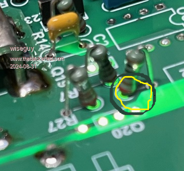
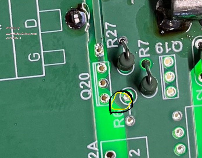
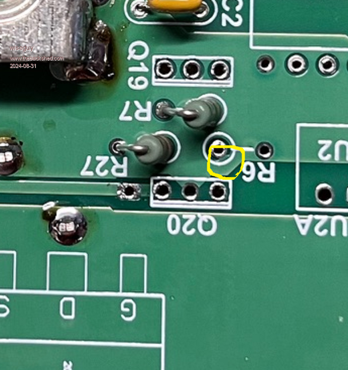
The reasons for presenting this issue here are two fold, one be cautious about assuming that the blank PCBs I supplied have been manufactured defect free. Two this emphasises the benefits of testing at low currents the functionality of the various circuits before applying full power. Lastly it makes a bitt of a mockery of their full electrical testing (but not Kelvin tests which is not meant to discover this type of fault anyway).
If at first you dont succeed, I suggest you avoid sky diving....
Cheers Mike |
| |
KeepIS

Guru

Joined: 13/10/2014
Location: AustraliaPosts: 1679 |
| Posted: 06:48am 31 Aug 2024 |
 Copy link to clipboard Copy link to clipboard |
 Print this post |
|
Wow, thanks for that update. I'll swap out R4 when I get a chance, even though I'm using 2W modules, less heat - better.
Yes even now, anytime I touch anything in the inverter, I always go the extra mile and power it up with a tiny 3A variable power supply, with inverter in test mode, and bring it to life slowly.
It's all too hard.
Mike. |
| |
Revlac

Guru

Joined: 31/12/2016
Location: AustraliaPosts: 1022 |
| Posted: 08:31am 31 Aug 2024 |
 Copy link to clipboard Copy link to clipboard |
 Print this post |
|
I just had a look at the 2 power boards and around R6 looks the same as in your photo above, I will have to get to it using the big illuminated magnifying glass.
Cheers Aaron
Off The Grid |
| |
KeepIS

Guru

Joined: 13/10/2014
Location: AustraliaPosts: 1679 |
| Posted: 06:35pm 31 Aug 2024 |
 Copy link to clipboard Copy link to clipboard |
 Print this post |
|
I have one V2 PCB, put it under the electronic microscope, the same fault, R6 is effectively shorted, looks like a careful job for the Dremel - that is just ridiculous.
I made the 2nd power board for the new inverter with a V1 board, I still have another two of those.
It's all too hard.
Mike. |
| |
mab1
Senior Member

Joined: 10/02/2015
Location: United KingdomPosts: 209 |
| Posted: 07:43pm 31 Aug 2024 |
 Copy link to clipboard Copy link to clipboard |
 Print this post |
|
Just checked mine - couldn't see under the resistor but R6 is shorted.
Glad you spotted this before i started testing  . I can change R4 too, then i need to start fitting the FETS with their ferrites. . I can change R4 too, then i need to start fitting the FETS with their ferrites.  |
| |
wiseguy

Guru

Joined: 21/06/2018
Location: AustraliaPosts: 1156 |
| Posted: 12:35am 01 Sep 2024 |
 Copy link to clipboard Copy link to clipboard |
 Print this post |
|
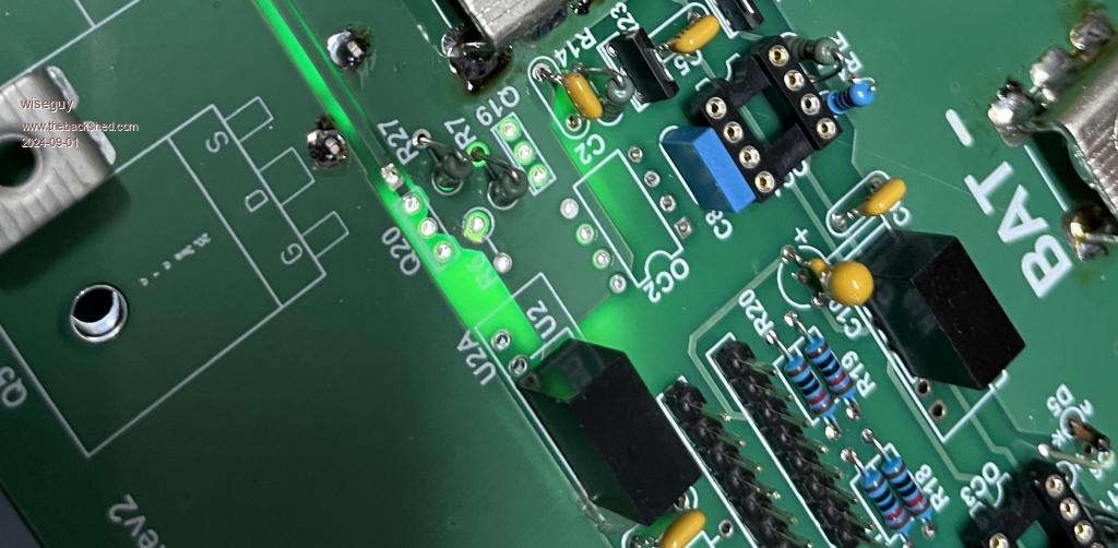
Sorry gentlemen all the Power PCBs have this damn defect and need to be fixed. I have lodged a complaint to JL with pictures I'll let you know their response. It would be nice if they offered to send replacements to everyone I have already sent them to but I suspect I will be lucky if they will even offer to replace them or give me a store credit (I would push for replacement).
If anyone would rather replacements (assuming JLCPCB will come to the party) I am happy to send out their replacements if you are happy to pay for postage. If you have already loaded the parts and dont have a good solder sucker I suggest sacrificing the 1K resistor by cutting the leg at the top and then pulling both halves out after heating with the iron and using solderwick (I call it "track lifter" - be careful!) to clean out the holes.
If you have a sharp scalpel/hobby knife you can cut the sliver off but being 2oz board it is not all fun to do. It is also good to use a backlight behind the board as it helps to see the results.
RogerDW and Bryan being locals we can work out picking them up sometime - if we get the offer of replacement...
My repair in progress started with a dremel
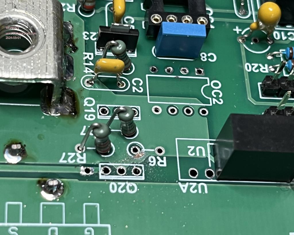
Finished using scalpel
If at first you dont succeed, I suggest you avoid sky diving....
Cheers Mike |
| |
| |
  Page 10 of 13 Page 10 of 13   |

