|

|
Forum Index : Windmills : F&P@PE
| Author | Message | ||||
| GWatPE Senior Member Joined: 01/09/2006 Location: AustraliaPosts: 2127 |
I have just hooked up the new AxFx mill atop the pole where the F&P mill once was. Same blades, YawBox, furling, and loading. All works. Cut in was at approx 40rpm, 0.2W measured into 24V battery. Could not feel the windspeed. Approx 1kph. The Davis cup anemometer was stopped. Mill rotor is slightly overloaded. This has a cap voltage doubler on 24V and 48V, with cap coupling to 24V rectifier/battery and 48V rectifier/battery. Over voltage protection stops mill in approx 0.2s. about 1 revolution from 200rpm. Just a Tch sound and the mill is stopped. The cap voltage doublers seem to give a softer braking when the loading is removed, as the voltage to trigger the braking is obtained at a lower wind energy. The max power is yet to be measured as furling is very conservative. approx 8m/s gives around 20% furling. I am very pleased with the operation so far. My original AxFx mill has faster response to wind changes, but both produce power and spin in the lightest of winds. I should not get questions whether the stopped mill is broken again. There is a difference in the sound this new mill makes. A bit like a motorbike a long way away. The new unit looks a lot like my F&P from the outside, but with a rear cover plate. Have to wait for some more steady winds to get some more comparisons with and without the various cap arrangements. Gordon. become more energy aware |
||||
| GWatPE Senior Member Joined: 01/09/2006 Location: AustraliaPosts: 2127 |
Some preliminary tests results for the new AxFx alternator with the dual loadings are: initial battery charging, 24V cap doubler system cutin at 30rpm[approx 0.5W]. Gives 5W at 60rpm into 24V, and 48V cap doubler cutin. At 120rpm, 24V loading is approx 10W and 48V loading is 15W. At 200rpm total power is approx 120W. Upper power at 350rpm was 550W. The Cap coupling allows the windmill rpm to still increase, at the point the 48V battery would load heavily. Maximum power will be limited by furling at under 1000W. My objective for priority automatic 24V trickle charging works as planned. The extra power when it is windy is automatically supplied to the 48V system connected to the normal grid side house loading. As a comparison, my F&P mill provided no charging at the lower wind levels, as it was not turning. I will plot some numbers when the logging system is up and running. The [output power] v [rpm] gives a nice loading curve. not sure if the rpm tracks the windspeed linearly yet. Having 12 magnet pairs makes the rpm calcs easy, as the mill gives 10Hz at 100rpm. I have removed the direct AC coupling Caps from the 24V loading as these stalled the blades. This has been the first indicator of how different the electrical behaviour of an AxFx machine is to a F&P. Gordon. become more energy aware |
||||
| GWatPE Senior Member Joined: 01/09/2006 Location: AustraliaPosts: 2127 |
The new AxFx mill has maxxed out the PVE1200 during the night. Power meter on the AC recorded a grid export of 1140W. Will be detuning the mill and making a revised overvoltage limit. The mosfets are no match for the mill output. Have resorted to the relay across the AC. The mill is a bit of a beast now. It is not wise to make any connections/dis-connections under load. The mill easily sustains an arc and ruins clipleads. The mill is well controlled with the overvoltage brake. The same blades with 4ohms load keep the mill under control. As a comparison, the F&P mill was able to get away, so the wiring resistance of the F&P, under 1ohm per phase for the delta wired series80 7s2p, gives the iron at equivalent to at least 3 ohms series resistance. No wonder the AxFx produces so much more power for the same blade/furling/loading settings. Next step bigggggger blades of course. Gordon. become more energy aware |
||||
oztules Guru Joined: 26/07/2007 Location: AustraliaPosts: 1686 |
HeHeHe..... got some power under the hood now? Now you know why I have forklift relays to stop it .... Herb was right about the armature reactance of the F@P I think. ........oztules Village idiot...or... just another hack out of his depth |
||||
| JimBo911 Senior Member Joined: 26/03/2009 Location: United StatesPosts: 262 |
Gordon That is fantastic news, job well done. Bigger blades it's gona be AWESOME!! Put a Cage around that BEAST. Jim |
||||
| GWatPE Senior Member Joined: 01/09/2006 Location: AustraliaPosts: 2127 |
Hi Jim, cages are to contain wild animals. Mine is just a beast. The mill runs really sweat. Just have to be careful with bare wire ends. The first point of call in the wiring is the mechanical braking switch. I know that I can lower the mill in a storm, as this was done on several occasions with the F&P mill head. Don't expect to do this again now. The overvoltage ccts work well with the grid inverter. If the inverter loses connection, the mill just stops. The Latronics PVE1200 inverter has a timing loop that continues to try and restore the grid connection when there is sufficient input voltage and grid available, but insufficient power to export. The solar inverters don't do this and lose connection in this situation. This happens with SMA inverters. The way the mill works now will enable me to remove some more wiring interlocks. We have had some severe weather here recently, with more today. I hope to post some recordings and some output AC voltage waveforms in the next day or so. The magnets in my rotor are spaced 5mm apart on the rotor plate, and the plates are 18mm apart. Will be interesting to see the resulting waveform. Gordon. become more energy aware |
||||
| GWatPE Senior Member Joined: 01/09/2006 Location: AustraliaPosts: 2127 |
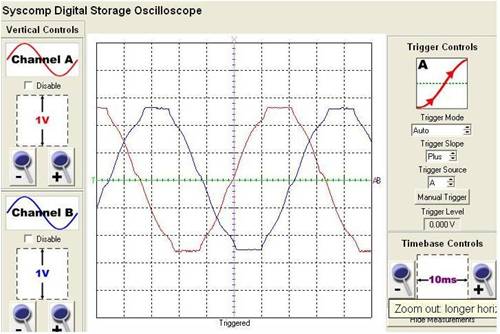
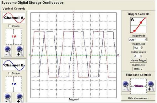
Had some time, so I have put together some graphs. Unloaded, gives a good sine wave. 2 graphs of waveforms as seen on the rectifiers. Light loading at just above cutin, and the second graph producing approx 300W 

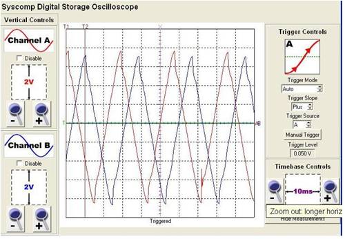
This graph is the AC waveform across the alternator, for 2 phases. The AC coupling caps do modify the way the windings work. There is no DC current in the coils. The voltage rises at a steady rate, to a maximum and then reverses. 
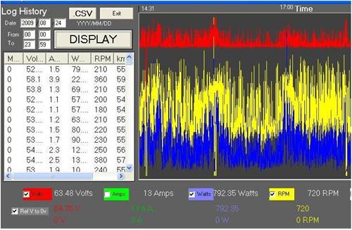
The caps are operating at a temperature of 24C, and the rectifiers are at 31C. These same caps were in the F&P setup. They are passing more current and operating cooler with the lower output frequency of the AxFx. approx 1/4 the frequency. This next pic is some sustained power outputs of this mill, that is furled heavily at winds above 9m/s. This has 2.4m rotor, into nom 48V loading. 
The max power recorded has been over 1000W, but this recorded portion gives 790W max. Average is 200-300W. I have detuned this with a modified loading and shutdown at high windspeeds. There are 3 shutdown periods shown on the graph. Protection in storms is important and this system now works pretty well. The bigger blades will bring the average power up some more. Still have to balance the blades. I have 2 blade sets to evaluate yet. Gordon. become more energy aware |
||||
oztules Guru Joined: 26/07/2007 Location: AustraliaPosts: 1686 |
Looking good so far. I can't help but feel that you have the prop and the alt underloaded. 700+ rpm for 700W is much higher than I would expect. The blades must be running about 1.4 x TSR...., and that alt is running at twice as fast for 700w than I would expect.... I wonder if some bigger caps may tame the rpm down a bit, and give the alt some load... ie come back to TSR 6-7.... is this right??... you do have caps in series all the time? Interested to hear that the unloaded is a good rendition of a sine wave. I had wondered how you would go with the mags that close and at 19mm gap. They are more flexible than I thought. .........oztules Village idiot...or... just another hack out of his depth |
||||
| GWatPE Senior Member Joined: 01/09/2006 Location: AustraliaPosts: 2127 |
Hi oztules, The first graph shows the waveform just at cutin. The waveform is slightly fatter than an ideal sinewave, but what the heck. The only option is to reduce the magnets and coils, and that would not do. The can was the limiting factor. On my original AxFx mill, the magnets are touching. The TSR is high, and is similar to my first mill. The mill is fully AC cap coupled. The mill stalls heavily without the caps. Very electrically stiff. The machine is 2.4m dia and maxxed out at around 12revs per second in 12m/s winds, heavily furled. The TSR is approx 7.5. There would be a point at a lower windspeed where the TSR is higher. I do not have a good correlation yet with rpm v windspeed. There is not sufficient blade noise to indicate a TSR problem. I may be able to do away with the series caps with bigger blades, and only use the cap voltage doubler. These are early days yet. The magnets are not even properly encapsulated yet. One set of my new blades[2.9m dia] are much thinner, so these will operate better with a higher TSR[same loading as present]. The 2nd set[3m dia] are longer versions of the current blades. These will require more loading[probably candidate for no series caps]. I need to do things with a system, to reduce the number of times the mill is lowered and raised. All will be tested eventually. Have to wait for the weather to ease up a bit. The weather must be hammering your place by now. Wish U had your mill flying? I hope to not need to make a new stator with less turns. The series caps do allow this coil rich stator to work at a lower system voltage. The low temp of the caps is a good sign. These same caps on the F&P mill were operating at over 45C The F&P mill did produce as much power on 1 occasion, but in hindsight, this was a result of the furling pivot seizing and the mill really getting away. At least now, the mill can be stopped with the flick of a switch. Need to wait for a break in the weather now. Gordon. become more energy aware |
||||
oztules Guru Joined: 26/07/2007 Location: AustraliaPosts: 1686 |
My mistake. Upon a quick real calculation, TSR is pretty close, it was the volts/rpm that had me in a spin. It will support significantly bigger prop with direct coupling... it would put out some serious power then. not as much as phils I suspect, but much greater than 1kw for sure... will be worthwhile.... furling will become far more important then from a heat perspective, than Phil suffers. It would also lend itself to even bigger blades again, and low furling to harvest the low wind power very effectively.. and forget about high power all together. ........oztules Village idiot...or... just another hack out of his depth |
||||
| JimBo911 Senior Member Joined: 26/03/2009 Location: United StatesPosts: 262 |
Hey Guys I am doing my best to understand TSR, blade size, loading etc may be you could tell me some thing simple like (the alternator is to powerful for the existing blades)or put it in simpler terms so some one like me really understands what Gordons trying to do. Thanks Jim |
||||
| Gizmo Admin Group Joined: 05/06/2004 Location: AustraliaPosts: 5078 |
Hi Jimbo This forum thread has some advanced technical stuff it in, I dont even pretent to understand some of it. 
Because we like to keep a thread flowing, without getting too sidetracked, I would suggest you post a new thread asking for some help on TSR etc. As a rule, people are happy to answer new questions. Also check out the Glossary page http://www.thebackshed.com/Windmill/articles/Glossary.asp Glenn The best time to plant a tree was twenty years ago, the second best time is right now. JAQ |
||||
| GWatPE Senior Member Joined: 01/09/2006 Location: AustraliaPosts: 2127 |
I have just looked at the numbers and at the moment, the piclog is not providing realistic numbers. There is a 200% variability in the power readings at a particular rpm. The 1 second timing window for the rpm measurement is most likely the problem. The power readings are probably accurate. The output is an increasing power curve with rpm, with cutin at around 60rpm, peaking at 600W at 500rpm. The loading at present is reducing at the higher power levels, so direct loading needs to be tested. This configuration would likely suit a decent VAWT. More testing will have to wait till I am over the FLU. Gordon. become more energy aware |
||||
| Smart Drives Senior Member Joined: 06/07/2009 Location: AustraliaPosts: 115 |
I have only read the first couple of pages of this NOVEL so i am not sure if this has been mentioned but the smart drive shafts can spin in the bearings it is recommended to use a bit of loctite. That might explain lack of power problems . Cameron. All smart drive parts sold Custom built turbine parts on Multicam flatbed CNC Router |
||||
| GWatPE Senior Member Joined: 01/09/2006 Location: AustraliaPosts: 2127 |
Hi Cameron, You have missed a significant point, clearly shown in photos in the thread, that my windmill never had a F&P shaft, or F&P std rotor. The magnet ring was pressed into a brake drum style rotor, and the blades attached to this. The new AxFx alternator has the same type blade mount. The method of frequency measurement based on the AC output waveform and the time it takes to make a reading are more likely problematic. I take a current reading just prior to the start of the rpm reading, and then take another current reading just after. These current readings are averaged, prior to logging. I will come up with a solution. Gordon. become more energy aware |
||||
| Smart Drives Senior Member Joined: 06/07/2009 Location: AustraliaPosts: 115 |
Oops , that was important. I have all the efficiencies of 100S 80S and 60S in star and delta for 12 24 and 48 if anyone wants to know a particular one. 80S wired in half series half parallel in 24v (STAR)gets to 85%. Cameron The original graphs i have are quite small so there is room for error when interpreting. approx 5% All smart drive parts sold Custom built turbine parts on Multicam flatbed CNC Router |
||||
| carl1 Regular Member Joined: 16/04/2007 Location: AustraliaPosts: 79 |
Hi Cameron if you have data can you post them please. I have posted a few power output graphs which are true test results done on a lathe, but I did not record a lot of efficiency tests. Harald |
||||
| GWatPE Senior Member Joined: 01/09/2006 Location: AustraliaPosts: 2127 |
Hi cameron, efficiency of a purpose built AxFx mill should be above 90%, probably between 95-99% at the low end of the output spectrum. Efficiency is highest at lowest power levels. It is amazing how much additional power can be extracted from the same winds with the same blades, just by changing the alternator. I will be making a new Aluminium housing alternator. I will need to redo the assembly of my first unit to fully seal all the steel joints. The caulking used by the car industry looks promising. Steel joints, sealed with paint, seem to end up with moisure impregnation and internal rusting. The rusting has changed the mating surfaces, and even after a year, has caused the F&P alternator to start poling. This is one of the reasons I am switching to Aluminium and replacing this F&P unit with a new AxFx. I think that the only machining will be the aluminium outer ring. I hope to reduce the weight significantly as well. Gordon. become more energy aware |
||||
| GWatPE Senior Member Joined: 01/09/2006 Location: AustraliaPosts: 2127 |
I have modified my piclog and have improved the dynamics of the rpm and current measurements. now have additional analogue and additional digital filtering of the raw data. The effective data sampling time is increased to 2 sec, but for 10sec logging interval, is still fast enough. My suspicions with the erroneous rpm was confirmed. Here is the power v rpm graph for the mill. Cutin is around 50rpm, approx 5W output, increasing with a cubic loading up to 433rpm producing 728W. Here is the graphed data, for a 2 hour recording session. The data was only sorted, no outliers found. The full potential of this alternator is clearly not reached, as there is no flattening of the output curve. The larger blades will be tested asap. This mill produces 50Hz AC output at 500rpm. The cap arrangements, with 3phase cap doubler and Series cap coupling work at lower frequencies as well as those obtained with a F&P mill. I have 12 x 560uF 350VDC back to back caps in the doubler, and 6 x 820uF 350VDC back to back caps in the series arrangement. I tried a larger series cap system, but this overlaoded the mill, and power output decreased. This is correlating well for the winds and rotor size/furling point that has been tested. This last test confirms that caps really give almost ideal loading characteristics for even a battery loading. This stator would normally be useless on even 48V loading, but caps allow it to perform probably better than a stator wound with optimum turns for the load, but without caps. Would be good for some other serious windmill enthusiasts to provide results from their own cap testing experiments. Gordon. become more energy aware |
||||
| GWatPE Senior Member Joined: 01/09/2006 Location: AustraliaPosts: 2127 |
Have just tested 3m blade set on the new AxFx mill. These were same airfoil profile as 2.4m set. The windmill output did not change any measurable amount. The furling and loading were unable to extract any significant amount of additional power, even though the swept area had increased by 1.5625. The TSR was higher as the blades had tip noise for the same rpm. the next step was to increase the loading. I increased the cap size, with the cap set that had previously stalled the rotor. Power output increased. good sign. I added the 1500uF series caps that I had calculated would be needed to the 820uF set. The power output jumped substantially. The last calcs has the windmill now producing the same power at 25% lower windspeed. Max rpm has reduced from 430rpm to 350rpm. Furling is more gentle and the windmill produces approx 800W max now. The average power is now approx double that of my original 2.1m rotor AxFx mill. The output should be 100/46 times, but it is pretty close. This concludes well, for the effort. The design has 50% more magnet material to my original AxFx, and can easily produce 100% more power. This concludes that the simpler design, even though bigger and heavier can out-perform the really difficult to build high tech unit. I doubt there will now be many days when this windmill stops turning now. Even on a low wind day like today, the mill has produced 0.9kWhr. Can't wait to see how it does in a storm.. Plans are under way for the new model. Gordon. become more energy aware |
||||