
|

|
Forum Index : Electronics : MAD/OZ AC/DC Charge Controller
| Page 1 of 9 |
|||||
| Author | Message | ||||
Madness Guru Joined: 08/10/2011 Location: AustraliaPosts: 2498 |
Just received the new PCB's today for the GTI/PV charge controllers. Master PCB 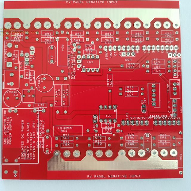 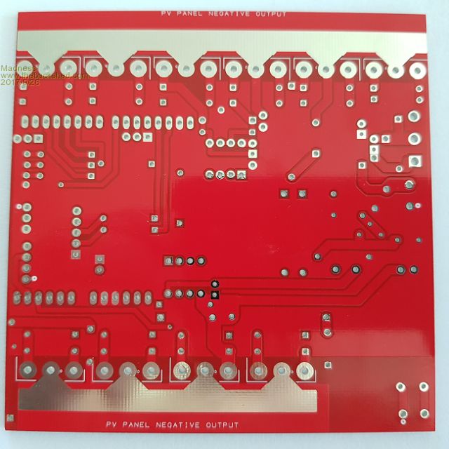 Slave PCB 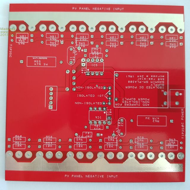 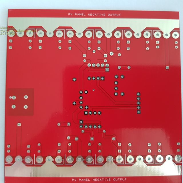 These will allow any combination of up to 4 GTI's or PWM PV panels to the battery, allowing control of around 20KW of panels with both master and slave PCB. It is suitable for 24V or 48V but not 12V as the driver chips require 18V. The best PV panels to use the ones with a maximum power voltage (VMP) of 30.4 or close to that. Having 2 of these panels in each string give maximum power at 60.8V which is just above the 59.2V Absorb voltage required for many batteries. Yes a $1,000 plus MPPT charge controller will in theory give slightly more power from the same panels. However, if you build your own controller for less than $100 you can buy a lot more panels with that extra $900, I recently bought 5KW of secondhand panels for $700. So for the same amount of dollars you will have significantly more power from your PV panels. This is based on Oztules design in this thread, my version has the MOSFETs, isolated power supply and multiple banks of MOSFETs on the PCB. Over the next couple days, I will get a PCB assembled and running. These will also run on Oztules code with the addition of control of the extra digital output pins. I am working new code that will include temperature compensation and the ability to control two separate dump loads (ie hot water system) to take advantage of excess power, I plan to use to control air condition in the container where I have my batteries and inverter. For those new to this, some Inverters inculding the Ozinverter will allow the connection of a Grid Tie Inverter (GTI) to the AC output of an Off Grid Inverter (OGI) this is called "AC Coupling". The excess power generated by the GTI passes back through the OGI to the battery bank. Some advantages of this are the use of less wiring from the PV panels as it running at a much higher voltage, it takes advantage of the GTIs maximum power point tracking, during daylight the GTI adds to the capacity of you OGI allowing greatly loads and GTI's are readily available second hand for minimal cost. One big disadvantage is that a GTI is designed to make as much power as possible for exporting to the grid, this a problem with an off grid power system as once the batteries are full you need to stop charging them or it will cause harm to the batteries, some types are more susceptible to this than others. However there is now a solution thanks to Oztules and upgrades I have added. With this control board, we can control the charging of the batteries using MOSFETs and a PWM signal that rapidly turns on and off the connection to the PV panels, therefore, reducing the power going to the batteries as they get towards full charge. This is controlled by a Microcontroller called an Arduino and gives us total control of the charging at a fraction of the cost of commercial charge controllers. I will post photos and details of the asembly as I go. There are only 10 types of people in the world: those who understand binary, and those who don't. |
||||
| Clockmanfr Guru Joined: 23/10/2015 Location: FrancePosts: 429 |
Nicely explained Madness. Love the painting by numbers boards, excellent. Had a few electronic guys mumble about my boards being "painting by numbers", but at least normal folk can readily understand what's going where, with fewer mistakes, and easy to repair in the future. Also helps my memory and stops me hunting/ getting paper work out. Getting the battery voltage to your circuit at the GTI, when its on the PV installation building some distance away from the Battery shed/building. I have ordered a few of these...... http://www.ebay.co.uk/itm/Tenda-PH3-1000Mbps-PLC-Powerline-Network-Adapter-KIT-Gigabit-Power-line-Adapter/253063478317?s sPageName=STRK%3AMEBIDX%3AIT&_trksid=p2057872.m2749.l2649 http://www.ebay.co.uk/itm/Tenda-PH3-1000Mbps-PLC-Powerline-Network-Adapter-KIT-Gigabit-Power-line-Adapter/253063478317?s sPageName=STRK%3AMEBIDX%3AIT&_trksid=p2057872.m2749.l2649 Not sure of there range over the AC OzInverter 230vac Mini Grid, interference signal loss etc, I need about 500 meters. But will test them. In simple terms ....... Can we shape/sense the battery voltage directly into the unit?, and at the GTI AC input/output let your Arduino see the battery voltage rise and fall and adjust accordingly?. Everything is possible, just give me time. 3 HughP's 3.7m Wind T's (14 years). 5kW PV on 3 Trackers, (10 yrs). 21kW PV AC coupled SH GTI's. OzInverter created Grid. 1300ah 48v. |
||||
Madness Guru Joined: 08/10/2011 Location: AustraliaPosts: 2498 |
Why would someone have a bitch about having the values of the components on the board? I would have thought Ivory towers would be in short supply these days. I just did a quick google and the consensus is around 200 - 300 M is the range of a power line network, but they are connected to the open grid as well so in a closed grid that may be different, selecting a slower speed on the adaptor would worth a shot also. There are two options that come to mind to control it remotely, one is to send the voltage as you mentioned or send the PWM value of the master. I think the second is less likely to have controllers in conflict. If one has gone into float and the other is still trying to get to absorb the first will back off and not be contributing any power as the other will be trying it's hardest to reach absorb voltage. On bright day this may not be an issue as the second may well produce enough power to get the volts up to absorb and then go to float. However, on a grey day it may never quite get there. If one is the master sending a PWM level signal the second will just play follow the leader. 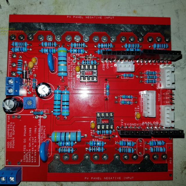 I have had to use long pins for the Arduino socket so there is sufficient clearance for the connectors below it. There are only 10 types of people in the world: those who understand binary, and those who don't. |
||||
oztules Guru Joined: 26/07/2007 Location: AustraliaPosts: 1686 |
This is a game changer board Mad, I can't find anything out there even remotely comparable. Handles huge current and cheap as you can get, while still having everything you could need to control lots of charging... of any source really. Don't know why this has not been done before up to this power level... but then none of the home brew inverters are any where near what you have got now either. Nice work. ........oztules Village idiot...or... just another hack out of his depth |
||||
| Tinker Guru Joined: 07/11/2007 Location: AustraliaPosts: 1904 |
Madness, do you have, by any chance, a kind of circuit diagram of that battery charging controller? It would help me a great deal to see how it works and if I could adapt it for LYP battery charging. Thanks. Klaus |
||||
Madness Guru Joined: 08/10/2011 Location: AustraliaPosts: 2498 |
Hi Tinker, Oztules "I don't do circuits" has rubbed off on me. If you look at Oz's thread you can follow the tracks on the PCB, that is basically what I did. If you get stuck let me know but it is not complicated. There are only 10 types of people in the world: those who understand binary, and those who don't. |
||||
| Tinker Guru Joined: 07/11/2007 Location: AustraliaPosts: 1904 |
Fair enough. I'm somebody who don't follow somebody else's tracks. I'm sure I can come up with my own solution, not in a hurry anyway, just interested. Klaus |
||||
Madness Guru Joined: 08/10/2011 Location: AustraliaPosts: 2498 |
Sometimes it is easier to follow others tracks, other times it is smart to take a different route. I would have to sit down and trace it out, only reason I have to do that is to save you doing it, I just have so little spare time. There are only 10 types of people in the world: those who understand binary, and those who don't. |
||||
| Warpspeed Guru Joined: 09/08/2007 Location: AustraliaPosts: 4406 |
[quote]Had a few electronic guys mumble about my boards being "painting by numbers", but at least normal folk can readily understand what's going where, with fewer mistakes, and easy to repair in the future. Also helps my memory and stops me hunting/ getting paper work out.[/quote] Absolutely ! The guy that has to repair it a few years from now may be YOU. And a part may have become burned to a crisp where the colours are no longer identifiable. Even new parts can be difficult to decide if its orange, brown or red. Or is that white or is it grey, or maybe blue or violet ? Even some of the integrated circuits have markings that are so faint as to be hardly legible with a magnifying glass under a bright light when the chip is brand new and perfectly clean. Putting the component values on the board make excellent sense. Cheers, Tony. |
||||
| Warpspeed Guru Joined: 09/08/2007 Location: AustraliaPosts: 4406 |
Yup. But its often very interesting to see how others have solved some of the problems. You yourself have suggested many ideas that I have then incorporated into my projects. Not a direct rip off, but some very nourishing food for thought. Cheers, Tony. |
||||
| M Del Senior Member Joined: 09/04/2012 Location: AustraliaPosts: 155 |
As the others said, this is a well put together layout, even I can follow the path and value of most of it. Not having a go at anyone, most of you have built a lot more than me lately. If all boards were done like this the world would be a simpler place. At work the guys doing the electronics systems have hells own problems sometimes following the circuit tracks, let alone values of componants. I think I will have to buy one eventually. Did I miss a price in any of the posts? Mark |
||||
Madness Guru Joined: 08/10/2011 Location: AustraliaPosts: 2498 |
I have been selling them for $5 AUD per PCB, I have a number of orders already that I will fill but I am not going to continue at that price. You can get 10 made and delivered for $20 USD after you include the hidden surcharge, but as soon as you order more than 10 the price per board doubles. If I ordered 100 then it is just over $200 USD, back to the same price per board. Tinker can verify you need to be careful with the orders as the price goes up very quickly once you go past 10 @ 100mm X 100mm. So after I finish the next design I will post the gerber files and let you guys do what you want with them. Maybe Clockman will make them available, I just don't have the time to do it. I have almost completed assembling the first one of these. Once I have confirmed that is okay I will order the next batch. The new design will allow adding a network card and SD card so it can log data and make it available over the net. Also, this will let you connect controllers located some distance apart and have them work in unison. For example, if you have panels on GTI that is 200 metres away from your batteries and other panels the one at the batteries could tell the slave at the GTI what percentage the PWM should be. My next project will be an Inverter monitor that will log State Of Charge current flow in and out of the batteries, voltage, inverter load and temperature, control fans and so on, this will be on an Arduino Mega with a TFT touchscreen. There are only 10 types of people in the world: those who understand binary, and those who don't. |
||||
Grogster Admin Group Joined: 31/12/2012 Location: New ZealandPosts: 9308 |
I am an electronics design guy, and I always put the component values on the silkscreen. I actually prefer that to using "R1" and "C8" kind of marking. The latter does have it's uses though, cos then you can find that component on the schematic - makes it quicker to service if you are looking for the most likely point of failure. However, having said that, I still much prefer the values on the silkscreen. It makes assembling the board that much easier, as you then don't NEED a parts-list....  I also put in the cap voltage ratings etc too. Technically speaking, there is no "Wrong" way to do this - it tends to be individual choice more then anything else at a standardized level. Perhaps if you were going to get thousands made or something, but if you are only doing a hundred or less.... Smoke makes things work. When the smoke gets out, it stops! |
||||
| Clockmanfr Guru Joined: 23/10/2015 Location: FrancePosts: 429 |
A schematic !!!!! HeHe. Nowadays, I am also a Member of the build the circuit as I go group. With the latest PCB software, just so easy to back tread and re-organise the layout to suit what is required. Especially with these projects being relatively robust and simple layouts. Ah yes I remember the 'R1' & 'C8' in the 1980's and trying to draw a 'schematic' and then 'ratsnest' to 'Conflicts' 'Routing' 'Spice' and 'Pcb layout' was a hard slog. Just so over complicated and departmentalised. As I say thank goodness for this modern PCB software. However, I see they still use generic and manufacturers code on components and not necessarily the actual component values themselves. Mind you with SMD as well I suspect the data base is getting huge.? With my A4 size extra thick copper boards, the PCB manufacturer seems to have trouble fine silkscreen printing component values around the FET gates. So I move the '0.6W 20k' the 'IN5819' and the '0.6W 5r6' printing around a little with the PCB software so they print okay. Or, do I have a bad board manufacturer? I still give folk actual size hard paper print copy of my boards. For a getting old person like me, with today's PCB manufacture, you just got a love todays technology and the way it all seems to interflow from one process to another so effortlessly! Sweet! What's the norms for silkscreen printing on PCB's today,? Is it a roller or inkjet printing? Everything is possible, just give me time. 3 HughP's 3.7m Wind T's (14 years). 5kW PV on 3 Trackers, (10 yrs). 21kW PV AC coupled SH GTI's. OzInverter created Grid. 1300ah 48v. |
||||
| Clockmanfr Guru Joined: 23/10/2015 Location: FrancePosts: 429 |
Yes, I think offering the 'OzMadCharging' board as an extra option, along with the 'OzInverter' Book and the 'OzInverterPower' Board, the 'OzControl' and the OzCooling board, might help others. Here we just ask for our costs back, the big double copper thickness boards are expensive, but the Postage to anywhere in the World does get hideously expensive. End of next year our lecture theatre here, Normandy, France, will be available for running courses. And we intend to do a couple week sessions on building your own 'OzInverter' and other RE stuff. I would supply a kit of parts for those participants attending as part of the deal, and then we can put one together. We have Gites accommodation for 6 persons and use of other nearby Gites. Wives and partners could be entertained, 2 hours to Paris from here, local distilleries', Luxury resorts/coast is 50 minutes away etc etc. Must rigoursly test that new 12 version of the OzControl board first, once I am happy I will post the Gerbers files on this forum. Everything is possible, just give me time. 3 HughP's 3.7m Wind T's (14 years). 5kW PV on 3 Trackers, (10 yrs). 21kW PV AC coupled SH GTI's. OzInverter created Grid. 1300ah 48v. |
||||
Madness Guru Joined: 08/10/2011 Location: AustraliaPosts: 2498 |
I have had a major failure today that appears to be caused by the GTI and has blown my inverters as well. Anyone waiting on PCBs I am happy to return the money as I would like to get to the bottom of this before causing anyone else issues. There are only 10 types of people in the world: those who understand binary, and those who don't. |
||||
| Clockmanfr Guru Joined: 23/10/2015 Location: FrancePosts: 429 |
Well that's a downer. Is the GTI at fault. Odd to bring down your Inverter as well. I can not really think how the Charger on the DC side of the GTI would bring it down. Everything is possible, just give me time. 3 HughP's 3.7m Wind T's (14 years). 5kW PV on 3 Trackers, (10 yrs). 21kW PV AC coupled SH GTI's. OzInverter created Grid. 1300ah 48v. |
||||
Madness Guru Joined: 08/10/2011 Location: AustraliaPosts: 2498 |
The GTI has a dead short in its MOSFETs or whatever they are, it turns on all looks fine but when it counted down to lift off the fireworks started instead. It then displays a message saying the VAC is out of range. It was working extremely well until this happened, it was a cloudy day with light to heavy cloud with some rain periods. It failed at around 2:15 and was close to going to float. According to monitoring on my Midnite Charge controllers, the solar power was at about 50% of its normal output. Battery volts was 55.2 so the GTI regulator should have been having no effect. I know when it happened as the monitoring stopped at that working due to no power to run the network. There were no big loads on either. At this time I do not know what caused this, maybe someone with more experience with GTI's might be able to shed some light on it. THe manual for the GTI also tells me the error I had before was due to less than allowed resistance to ground. There are only 10 types of people in the world: those who understand binary, and those who don't. |
||||
| Warpspeed Guru Joined: 09/08/2007 Location: AustraliaPosts: 4406 |
As this is a known to work method, it may have just been a random failure. Unfortunately if one small part does fail, that can lead to a cascading and very spectacular failure of the whole system. Unfortunately it is not usually possible to diagnose the original source of the problem from the resulting widespread damage. Even something as simple as a single dry soldered joint, may have been responsible. Cheers, Tony. |
||||
Madness Guru Joined: 08/10/2011 Location: AustraliaPosts: 2498 |
It has been running for a couple weeks, is that long enough to be conclusive that is working correctly? However I agree the cause could be anything, the GTI only cost me $5 so not a huge loss, however I will see if it can be salvaged, it did work so well. In the meantime I will go back to an Aero-sharp once I get the Inverter back in action. There are only 10 types of people in the world: those who understand binary, and those who don't. |
||||
| Page 1 of 9 |
|||||