
|

|
Forum Index : Electronics : Grogster’s Inverter Attempt.....
| Page 1 of 3 |
|||||
| Author | Message | ||||
Grogster Admin Group Joined: 31/12/2012 Location: New ZealandPosts: 9308 |
Hello all. 
Right! My turn at trying to do the impossible. 
My AeroSharp toroids arrived today, very helpfully sent to me by Madness from Australia: 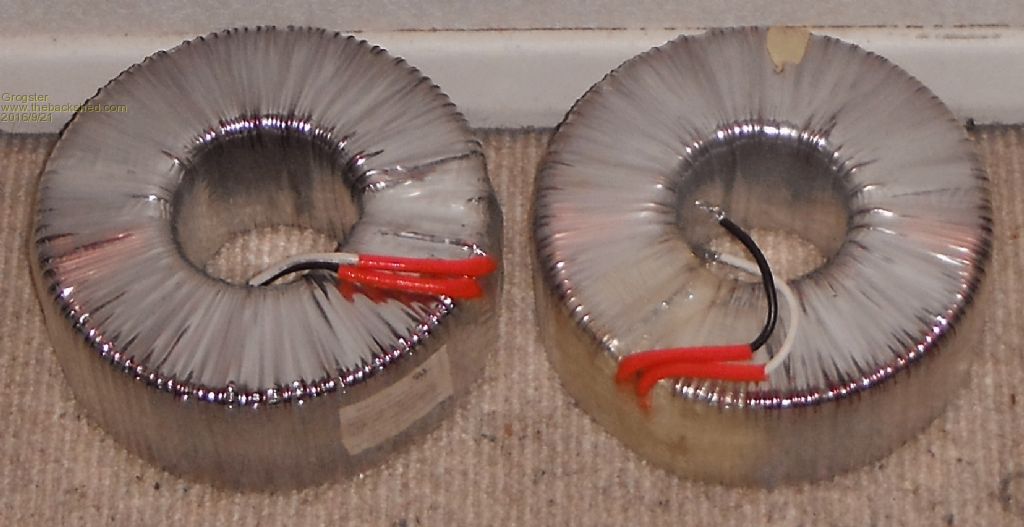
Madness had already very helpfully removed the top winding, leaving only the 230v winding, which is all I want. These toroids are 3kW ones, so should be good for about 13A of juice @ 230v when I am finished, although, I won't be running them at 100% load very much if at all. I am NOT stacking these ones, I am just re-inventing the 3kW AeroSharp unit, essentially. My inverter is being built for use in a Tiny House, so I don't need as much grunt as others would need to run a three or four bedroom house, that's why my build is smaller then some of the giants others have built. 
The 2nd toroid is just a spare so I can build another one later - or perhaps strip them both and stack-and-rewind a big 6kW toroid if I ever decided to do that in the future. My controller PCB's are almost finished. The system is built around four different PCB's, keeping them all to the 100x100 size so that this keeps the price for making the PCB's at a minium, as most PCB houses do the 100x100 size very cheaply. CONTROLLER: 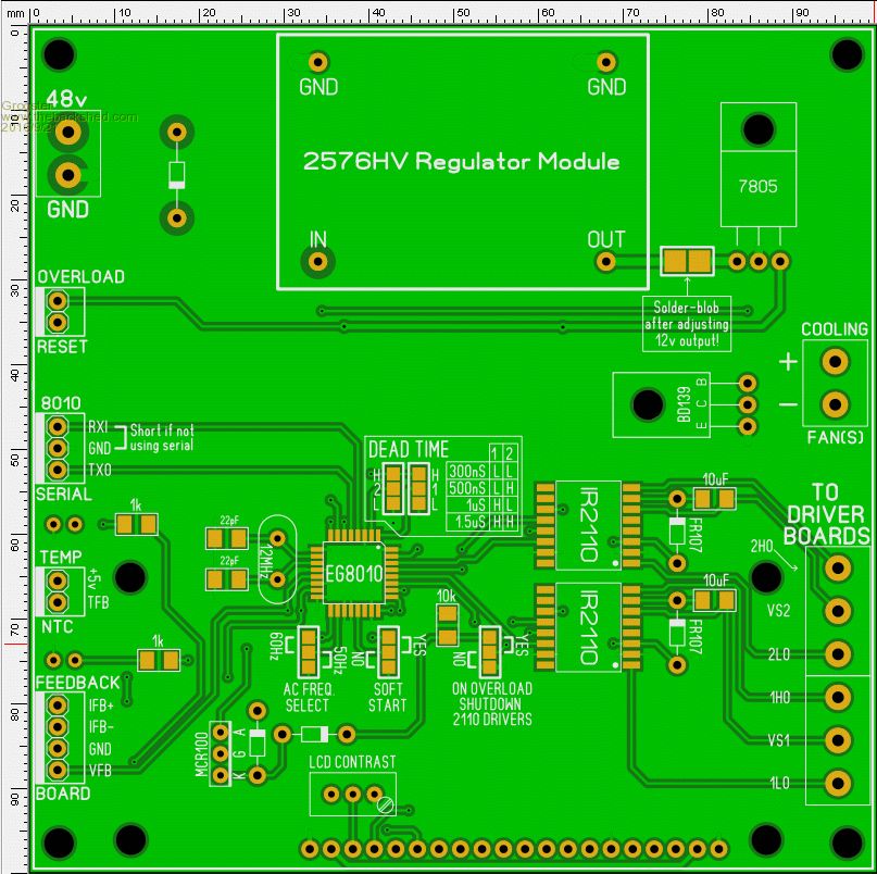
SENSOR PCB: 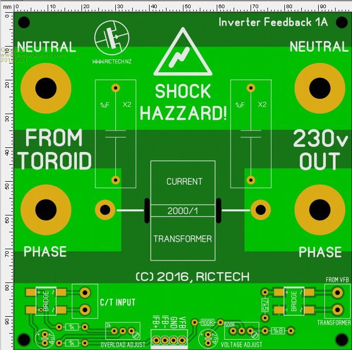
The power-board is currently in development, and there will also be a capacitor board with a bunch of 10,000uF 100v caps in parallel on the 48v rail - still a bit of work to do, but getting there. I will upload GIF's of the power board once I finish it. I have designed the power board, so that each one forms one H-bridge, and you can parallel up as many boards as you need to handle the toroid you are using. This allows me to easily add extra MOSFET power-board stages later to increase the capability of the inverter if I want. It also, again, keeps the PCB price right down by staying inside the 100x100 size limit. You can get ten 100x100 boards for about US$12, so that would allow you to build and use up to ten MOSFET power-boards(40 MOSFETS!) just by bolting extra ones on to the existing ones - all for twelve bucks worth of PCB. Here is a preliminary GIF so you can see how I am thinking: 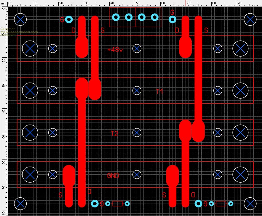
The red boxes are 10x3 copper bars, which are pop-riveted to the top of the PCB, and these form the heavy-current paths. The bottom copper of the PCB itself will be used to do the MOSFET gate components. The idea behind this, is that you can then line up many boards horizontally, and bolt them together using linking 10x3 copper bar to increase the inverter drive ability. I am using HY4008 MOSFET's in TO247 package, and these MOSFETS are capable of 80v/200A with a RDS(on) of 2.9 milli-ohms, and are designed specifically for "Power Management for Inverter Systems". I will post back to this thread with developments as they occur. Smoke makes things work. When the smoke gets out, it stops! |
||||
Madness Guru Joined: 08/10/2011 Location: AustraliaPosts: 2498 |
Those are rather professional looking PCB's Grog. Are you planning to get them manufactured with components fitted? Would be interested if you are planning to sell a couple. I have been thinking about etching copper sheet to overlay on my MOSFET PCB for current carrying, I had not thought of riveting, I plan to drill holes where needed and solder to the copper on the PCB underneath. If you don't ever get around to using the second torroid it would make a unmovable door stop in you tiny house. There are only 10 types of people in the world: those who understand binary, and those who don't. |
||||
Grogster Admin Group Joined: 31/12/2012 Location: New ZealandPosts: 9308 |
I will be building up the PCB's myself for my own one, but if there is interest, I can certainly make them to order or perhaps make a kit available via my website that includes all the PCB's and parts, or just the board etc.... Note my board allows selecting 60Hz for the American readers of this forum who may wish to build an OzInverter clone of their own, but want the 60Hz mains frequency.... This board also includes the SCR overload shutdown circuitry as discussed in the other thread. They make BLOODY good door-stops, those toroids! Can't wait to try this one out. With any luck, I will get some heavy cable for the primary for the weekend, and get winding the primary.  Smoke makes things work. When the smoke gets out, it stops! |
||||
Grogster Admin Group Joined: 31/12/2012 Location: New ZealandPosts: 9308 |
I have been working on the power board in CAD tonight, and this is what I currently have: 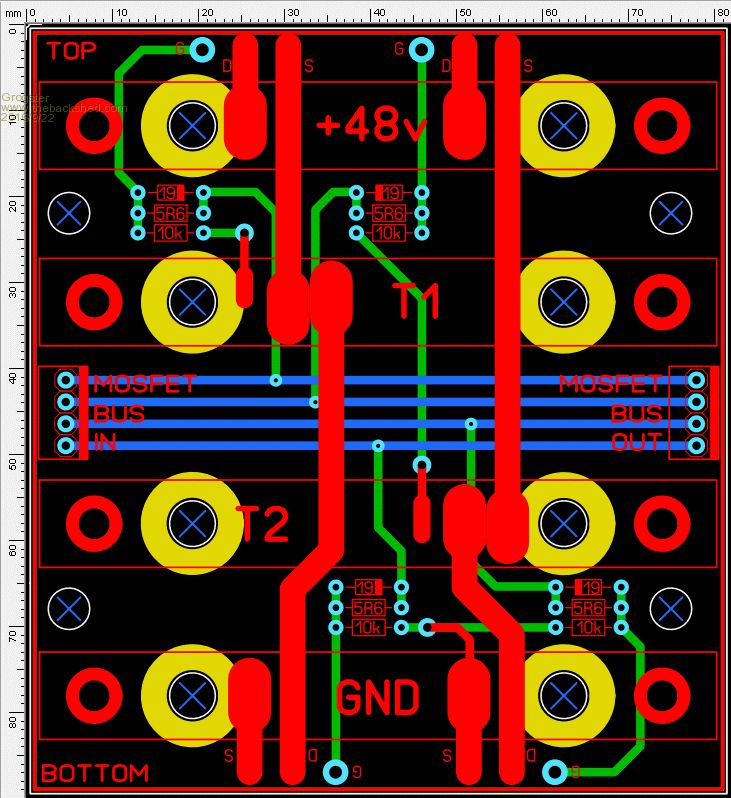
The bus-bars are now standard electrical bus-bars as used in meter-boxes and distribution systems. They are 10mm square brass, and come with studs and screws pre-fitted. Normally, these are used as neutral and earth bus-bars in the main distribution box for the house or where-ever. 
They also make and sell the little brass bus-bar joining strips, so this makes it dead easy to expand on this idea, by adding more boards in a horizontal arrangement, to up the power capability of the inverter. As mentioned above, you can get TEN of these boards from most PCB houses in China for about US$12 or so, allowing you to add up to ten power MOSFET stages to your inverter setup - just add the bus-bar joining plates between each PCB. You would probably need to double-up on the linking plates for really juicy inverters. These bus-bars are available in various lengths from any electrical wholesaler. I got mine from Radcliffe Electrical, and they cost about NZ$7 a bar, which I thought was a pretty sweet price considering how much current you could push through these if you wanted, and they already have the neat studs and screws all ready for connecting into. Radcliffe Electrical call them "Earth bar, 6-way, 2-stud, 6mm" if that helps anyone. I also got some 25mm-squared welding cable while I was there, but it is proving problematic because it is TOO flexible. It wants to bow away from the toroid, so I have another crafty plan in mind to get around this - I will use 2.5mm or so linking wire(which is much stiffer), and run three or four in hand depending on the size I end up using. I remember seeing one chap here on the forums using something like 20-in-hand or something for his primary!  Smoke makes things work. When the smoke gets out, it stops! |
||||
oztules Guru Joined: 26/07/2007 Location: AustraliaPosts: 1686 |
Don't see Vs1 and Vs2 in your bus... and B- would be good too. The 10k may be better replaced with 20k. Caps may be too far from the fets to do their job properly, the ftes may see a lot more ripple than they would have if the caps were placed as close as possible... we are switching a lot of amps........ and I just don't know about the stray inductance that will arise from this modular design. Not sure how many you can parallel before capacitance of the gates starts to overcome the signal and degrade it... you may need a stronger driver to keep control after 6 fets. You have introduced a lot of uncertainties all at once, so if it is unstable, it may be a handful to isolate the problems.... or it may just work fine...I have no idea really... certainly worth a try. Tests with the o/current seem to point towards success, hopefully I will have more concrete news sooner rather than later. .........oztules Village idiot...or... just another hack out of his depth |
||||
Grogster Admin Group Joined: 31/12/2012 Location: New ZealandPosts: 9308 |
These boards are still very much a work in progress. 
I can still change it - nothing has been ordered. I will see if I can fit in 2x 10,000uF/100v caps per board. VS1 and VS2 are on the controller board, and the idea being that you connect them to the T1 and T2 bars with two separate wires. That way, they can see the entire array of modules. I assume by B- you mean the battery negative or ground? Bottom bus-bar. In my case, I am really only planning to connect three(maybe four) of these in parallel. With the 4008 MOSFET, three would probably be enough for my inverter I would HOPE, although, I can add an extra 4th stage if you thought it would be a good idea(16 MOSFETS). It would be optimistic for anyone(myself included) to connect up all ten boards.  Smoke makes things work. When the smoke gets out, it stops! |
||||
oztules Guru Joined: 26/07/2007 Location: AustraliaPosts: 1686 |
I get a bit twitchy when I deliver high impedance signals across a mechanically connected high current pathway, being pulsed with very high currents....just whimpy I guess. With the clockman or PJ type setup, there is no chance of a fault in the current lines, as there is no mechanical interruption that can occur. A single 3kw torroid inverter is still a stompin great inverter... they can still do 10-20kw if you give them a chance ( caps and wire and fets) It should very easily fulfill your requirements.... but go for 4 fets .... just for the start surges.... so you can start just about anything while still running the house. .......oztules Village idiot...or... just another hack out of his depth |
||||
Grogster Admin Group Joined: 31/12/2012 Location: New ZealandPosts: 9308 |
Hey Oz. 
Thanks for your input. Is your main concern that the connections to the MOSFETS are not soldered, and so thus a slightly iffy connection could result in huge I2R heating, and cause things to blow up? Among other things such as impedance you have already mentioned..... Take a car's starter-motor - these are a bolted connection both at the motor and at the battery, but if done right, you don't have any arcing or issues despite the fact that there can be hundreds of amps flowing when you engage the starter motor. I will take another look at this concept, and perhaps re-design. Smoke makes things work. When the smoke gets out, it stops! |
||||
oztules Guru Joined: 26/07/2007 Location: AustraliaPosts: 1686 |
No, it is more the stringing of the modules, the buss bars will be screwed together I suspect, and high impedance joints may develop, and voltages will be generated across the imperfection. This will turn up in your pulse drive waveform.... may complicate the switching. At least if you supply the vs1 and 2 and the B- direct to the fets via an independent route, you will have total control of what turns on and off and when, so the signal does not deteriorate when you have 200 amp spikes going through the buss bars, and across the mechanical inter- connections ( read weak points). Plus it is not hard to do with the signal lines. .....oztules Village idiot...or... just another hack out of his depth |
||||
Grogster Admin Group Joined: 31/12/2012 Location: New ZealandPosts: 9308 |
So it is better to have ALL your intended FETS on ONE board with ONE set of bus-bars? Would that be a better approach to take? IE: Bigger PCB and longer bus-bars, but only ever ONE set of bus-bars, and no linkages or mechanical joins. I'll follow up on this more tomorrow. 2:30AM here - Grogster sleep now......  Smoke makes things work. When the smoke gets out, it stops! |
||||
| Tinker Guru Joined: 07/11/2007 Location: AustraliaPosts: 1904 |
Brass busbars? Fine for earth connectors but I hope you are aware that their conductivity is nearly four times worse than that of copper. So their cross section ought to be four times larger than that of the connecting copper cable. I would not consider using them in my inverter to connect the mosfets to. And, as oztules said, the less screw connections the better. Klaus |
||||
oztules Guru Joined: 26/07/2007 Location: AustraliaPosts: 1686 |
Yes there are many things to take into account when designing high power electronics, and I suspect not too many ee's even have played with this kind of power. We need to keep signal separate from current lines where possible, keep high current runs as short as practical, keep the caps as close as possible to the fets etc etc etc.... and you will end up with the PJ style soon enough. The circulating currents here can get up in the multi hundred amps on surges, and it is here you need it not to fail. It is no good to have it humming along nicely at a few hundred watts, and then stumble when you switch heavy loads or use triac triggered kilowatt heat guns ( or hair driers)... thats when your design needs to be sound, and not introduce more noise into the trigger circuits than necessary. That said, this design seems pretty stable and I have done a lot of sinning that any EE would have apoplexy just looking at it I suspect... so they are very stable and can put up with a good deal of poor design, and still give excellent performance.... but for the power section........ don't stray too far from the "norms". I am not an EE, so don't know what I'm doing, so I keep to similar things I see them do in normal circumstances..... in simple terms... copy clockman/pj design, and it will work fine. Lots of other designs will work just as well or better, but I am not privvy to most of them. As your getting the boards made, just get them doublw thickness, and use lots of copper where it counts.... much simpler to deal with. ........oztules Village idiot...or... just another hack out of his depth |
||||
Grogster Admin Group Joined: 31/12/2012 Location: New ZealandPosts: 9308 |
Hi guys. 
Had not thought of brass along those lines AT ALL - figured if it was good enough for a mains switchboard, it would be good enough for this. However, as Tinker quite rightly points out, earth and neutral bus-bars don't tend to have the kinds of current we are talking about flowing along them, what with most houses service being about 80A or so I think..... I will go back to pure copper bar if I do indeed do it this way at all, so that idea is now dead. [Quote=Oz]Yes there are many things to take into account when designing high power electronics, and I suspect not too many ee's even have played with this kind of power. [/Quote] Correct. As an EE myself, I do lots and lots of tiny-current work and generally speaking, anything over 5A or so is a monster. 10A or more is generally NEVER come across in most of anything I do with electronic design. I do understand that huge currents require huge respect and more attention to detail, so I am glad of the comments thus far, as this allows me to rethink that idea of mine. I will go and have another look at how the others were doing it in the other threads, as that seemed to be acceptable practise. I've never built an inverter before, so I am learning this to some extent myself, as I go along with the rest of you.....  Smoke makes things work. When the smoke gets out, it stops! |
||||
oztules Guru Joined: 26/07/2007 Location: AustraliaPosts: 1686 |
Clockman has posted his power board here http://www.fieldlines.com/index.php/topic,148953.msg1037068.html#msg1037068 Village idiot...or... just another hack out of his depth |
||||
| Phil23 Guru Joined: 27/03/2016 Location: AustraliaPosts: 1664 |
Been meaning to mention, the very first post reminded me of Daisy Duke.... Hope that's not too much cryptic Aussie Humour for a Saturday night? Phil. |
||||
Madness Guru Joined: 08/10/2011 Location: AustraliaPosts: 2498 |
Has she got 2 big holes? There are only 10 types of people in the world: those who understand binary, and those who don't. |
||||
Grogster Admin Group Joined: 31/12/2012 Location: New ZealandPosts: 9308 |
LOL!!!!!   
You guys. 
But yeah, nice set of toroids....... Smoke makes things work. When the smoke gets out, it stops! |
||||
| Phil23 Guru Joined: 27/03/2016 Location: AustraliaPosts: 1664 |
Lol. The Dukes of ??????? Seven letter Locale. |
||||
| Phil23 Guru Joined: 27/03/2016 Location: AustraliaPosts: 1664 |
& here was I picking up what the Spell Checker missed. But now that it's been mentioned, I notice Toriods vary in size over time. (Just can't help asking Google's opinion). |
||||
Grogster Admin Group Joined: 31/12/2012 Location: New ZealandPosts: 9308 |
For everyone's information, Phil was referring to my spelling "HAZZARD" on the FB board - one extra Z..... This has been corrected. Smoke makes things work. When the smoke gets out, it stops! |
||||
| Page 1 of 3 |
|||||