
|

|
Forum Index : Electronics : GP’s inverter build
| Page 1 of 3 |
|||||
| Author | Message | ||||
| gpalterpower Senior Member Joined: 19/07/2009 Location: AustraliaPosts: 175 |
Hi all. I originally started this thread on Gizmos "building a new Inverter Project" , but decided its best to start my own thread as it could be lengthy. Sorry Gizmo. I should of asked before bombarding you with my stuff. Anyway I've been away from the project a while due to work, family, more work, holidays and some issues with PJ and their freight logistics. Back in December 2015 I contacted them to see if they could ship the control board, AND the main board in the same box, now that they were both available. It seems that you cannot order until they appear highlighted in the drop down box on the Ebay screen. A few emails back and forth, a payment to PJ and was all organised to have that done. After all, it was going to save me about $30 in freight...right! What could go wrong  . I figured if I received them by January, I would be able to make a good start over the christmas break. After waiting nearly a month it arrived at the post office late Jan. . I figured if I received them by January, I would be able to make a good start over the christmas break. After waiting nearly a month it arrived at the post office late Jan.
Excited I was when I got home to open it, only to find there was only the main board inside. An email to PJ to try and sort thing out. This was just the start of a loooooong drawn out process....It took 27 emails back and forth, many photos to prove that the 2 items could NOT possibly fit into the delivered box. Proof from my post office of the weight of the box and the main board listed individually so they could match weights with their logistics company, with more photos! To top it off, on the 27th email when they admitted wrong and would send me the missing item, I was informed that the company would be on New Year holidays for 3 weeks!! So for anyone out there who is attempting to purchase these parts from PJ to save a few bux....DONT!!! Just pay the double freight. Soooooo much easier. I finally received the control board (they paid the freight)mid March. Been shelved since then until now. I have some time up my sleeve and am getting back in to it. more info and pics soon. Marcus if it aint broke dont fix it!! |
||||
Grogster Admin Group Joined: 31/12/2012 Location: New ZealandPosts: 9308 |
I see floating around on the forums, that oztules and others have made their own inverter driver PCB. I don't know much about it, but as I understand it, it uses a cheap and readily available sine-wave driver board from eBay, and the rest of the system is built by yourself, so perhaps is a better option in terms of not having to rely on Chinese manufacturers and the associated confusion and/or long delays perhaps? What are your thoughts on that? Do you know anything about the home-bake inverter driver thing? You probably do..... I am looking very seriously at this now. Smoke makes things work. When the smoke gets out, it stops! |
||||
oztules Guru Joined: 26/07/2007 Location: AustraliaPosts: 1686 |
For about $10 or less you get all the parts for the 3 chip board. It is only a few drivers, a crstal, a few caps and a 8010 chip... works very very well, actually runs the fets and transformer cooler than the PJ can. I put one in a pj5000 24v unit for a bloke that killed his, transformer stays cold while idling for hours... big difference. There is a egs002 board on that thread as well.... probably 15 dollars to do that one. probably here is a good [place to start in that thread http://www.anotherpower.com/board/index.php/topic,1116.msg11614.html#msg11614 and here for the 002 http://www.anotherpower.com/board/index.php/topic,1116.msg11540.html#msg11540 ...........oztules Village idiot...or... just another hack out of his depth |
||||
Grogster Admin Group Joined: 31/12/2012 Location: New ZealandPosts: 9308 |
Ta. The Micromite chip has a pure sine-wave output Cfunction, so perhaps..... Anyhow, I will look up that thread you linked to. The problem I am having, is not knowing quite where to start. I have been following the inverter threads off and on for a year or so, but there is so much talking going on there and on the other forum(more then just a few pages of posts!), that I get lost trying to work out which method is best and/or the current preferred method. I design PCB's for a living, but I see boards have already been prototyped for this idea. I would be willing to produce professional boards and sell them on my website if anyone was interested in allowing others to build your design, Oz...... For the Micromite stuff, I supply part kits, blank PCB's or full kits. Smoke makes things work. When the smoke gets out, it stops! |
||||
oztules Guru Joined: 26/07/2007 Location: AustraliaPosts: 1686 |
If anyone wants to copy or emulate anything i have posted, then fine. I don't own anything I have posted, the forums do.... so it is all in the public domain as far as I'm concerned now. Your welcome to make a better circuit board.... not to hard to beat I'm afraid... double sided will get rid of a heap of 0r resistors. It may be better to have cross conduction protection too... but I have not seen any problem so far.... and I have tried to clobber it pretty severely. Incorporate a buck converter and fan and.... just where does it stop.... Talk to Clockman, you may be able to help him, help you regards the fet board. You don't want a sine wave .... you want the jump table to a sine wave, so you have a value you can scale ( load dependent)... ie scale value x the jump value to generate a spwm... then the next and next and so on.... at least thats how I see it anyway. Amplifying a sine wave is 50% inefficient at best. .........oztules Village idiot...or... just another hack out of his depth |
||||
| gpalterpower Senior Member Joined: 19/07/2009 Location: AustraliaPosts: 175 |
Well this is becoming somewhat a slower project than I had first anticipated , but I finally have had some time to work on the inverter with some updates to show. I purchased the Ferrite E core some months back and had a go at winding some heavy cable on to the coil former. By using welding cable and removing the outer sheath , I was left with a smaller diameter of 35mm cable. The max I could place on the former was 3 and a half turns which is ok but later found out that 35 mm wasnt going to cut it....so back to the drawing board. I procured some 8 x 2 mm enameled copper strip and made a former from timber. 3 layers of this will give me 48mm/sq . Needless to say it turned out a bit of a dud as the corners were too tight and didnt quite fit the former! 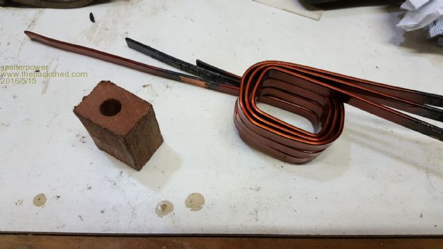
Change of stragedy and a new former with rounder ends was far better. The first attempt being with the larger (left) end which turned out to be far too loose, so unraveling the copper and having another go on the smaller end worked out much better and a neater fit. 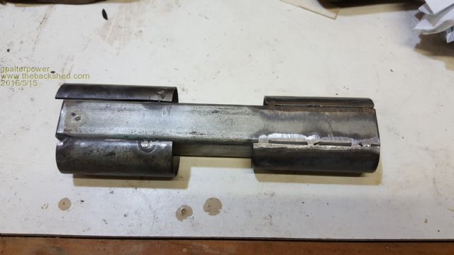
I had to cut the former so I could fit the wound copper. I found I could fit 4 1/2 turns on the former. ONE more turn than I expected. Is 3 1/2 turns an empirical design or is and extra turn a good thing? 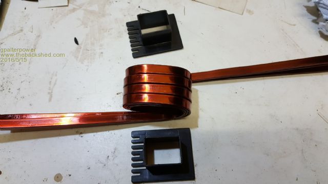
It fits neatly into the E core . 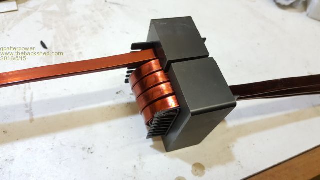
And made an ally case to hold things in place 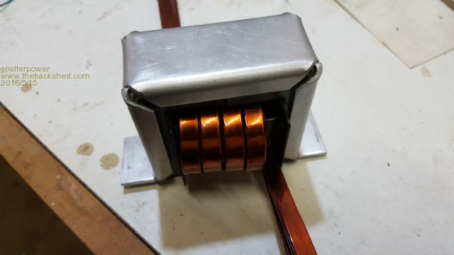
Next was the case where I placed the main and control board on their side and toward the top. I am planning on placing the fan on the outside above the main board thus drawing air up and thru the heat sinks as a wind tunnel effect. Im hoping this will cool things efficiently. 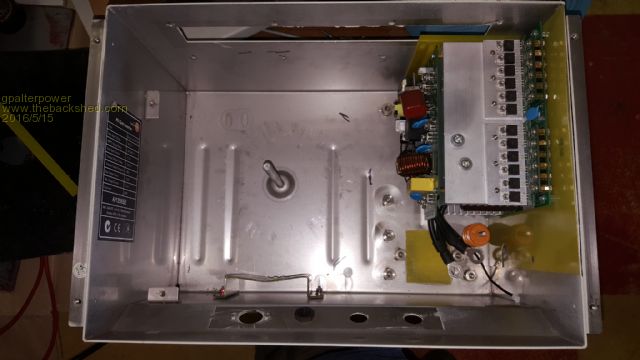
I placed a mat on the back of the case and allowed the toroid to sit flat on to that. 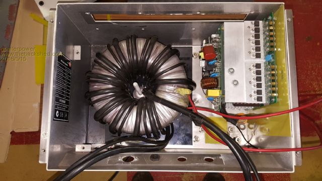
Things sure are getting crowded in there! Not 100% sure on battery connections where pos and neg battery attach, but Im gravitating towards the 2 black leads are NEG and larger heat sink is POS. Primary connections to the toroid via circuit breaker and choke are the 2 smaller heat sinks. Does that sound right? Thanks Marcus if it aint broke dont fix it!! |
||||
| Tinker Guru Joined: 07/11/2007 Location: AustraliaPosts: 1904 |
Nice to see that someone at last had the courage to copy what I wrote in "tinkers inverter project" with regard to winding these ferrite chokes. Now you are possibly kicking yourself when you read my latest on ferrite chokes in "building an inverter from scratch". Klaus |
||||
Grogster Admin Group Joined: 31/12/2012 Location: New ZealandPosts: 9308 |
Would not that juicy 8x2 enamelled copper strip not make for an excellent primary for the toroid too, over using thick sheathed cable? Exposed copper strip like that would be able to dissipate heat better for when the inverter is pushed hard. Again, I may well be missing something.... Smoke makes things work. When the smoke gets out, it stops! |
||||
| Tinker Guru Joined: 07/11/2007 Location: AustraliaPosts: 1904 |
Of course it does. But more for the reason one can fit a much larger copper cross section for the same # of turns through a given size toroid hole. Perhaps you have not yet read "tinkers inverter project" which I posted here late last year. Klaus |
||||
| Clockmanfr Guru Joined: 23/10/2015 Location: FrancePosts: 429 |
Yes..... The 3 pairs of cables from the Power Board base are Negative battery connections. The two split heatsinks are the Toroid Prinary connections. The big heat sink is the Positive battery connection. Like....... 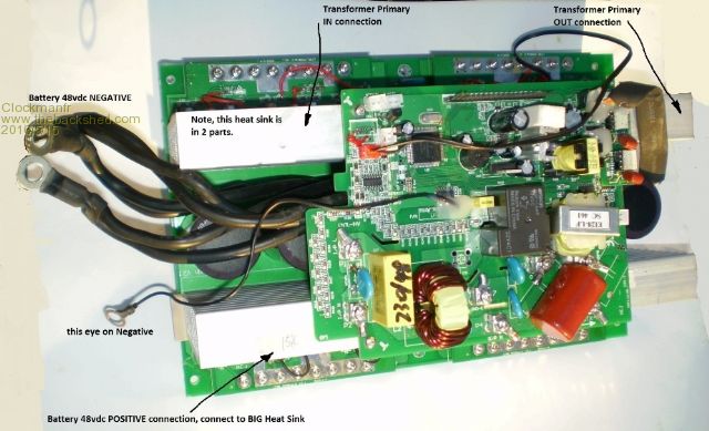
The toroid secondary connections go to the PJ control board. On our new boards we have got rid of the secondary cables, we use a sense coil for current and a 230vac light cable feed for the ac voltage regulation. Everything is possible, just give me time. 3 HughP's 3.7m Wind T's (14 years). 5kW PV on 3 Trackers, (10 yrs). 21kW PV AC coupled SH GTI's. OzInverter created Grid. 1300ah 48v. |
||||
| gpalterpower Senior Member Joined: 19/07/2009 Location: AustraliaPosts: 175 |
Tinker, I just saw your post and yessss, I am totally kicking myself after seeing that! DUH!! Its always the way though... a bargain pops up the day after you just made a purchase from somewhere else. Looks like those fronius may become a lot more popular now... some real bargains inside. BTW your inverter build is looking great, making your own boards. Totally impressed. 
Thanks Clockman. just confirming. I Hate seeing that magic smoke come out. you know its gonna be expensive! Marcus if it aint broke dont fix it!! |
||||
Grogster Admin Group Joined: 31/12/2012 Location: New ZealandPosts: 9308 |
Perhaps not. I will hunt that thread out and have a read, if you cover it in there. So many threads and forums with this stuff on it.... Smoke makes things work. When the smoke gets out, it stops! |
||||
| yahoo2 Guru Joined: 05/04/2011 Location: AustraliaPosts: 1166 |
apologies Grogster, I wrote a post for you with a list of all the relevant forum posts juicy bits and links about a month ago, but I didn't post it. the quickest way to a list of tinkers topics is to find his name in the topic starter or last post column and click. I'm confused, no wait... maybe I'm not... |
||||
| Clockmanfr Guru Joined: 23/10/2015 Location: FrancePosts: 429 |
No Marcus, No Magic smoke wanted..... but at these amps its more like plasma welding!!!! The New Boards. I supply all the real size Etching masks with the book, so the PCB's can be made at home. The OzControl board is single sided, but I now have a double sided on its way, which is shorter in length. The whole unit I suppose could replace a PJ as a swap in. This New 6-15kW Power Board has many improvements. 'Why re-invent the wheel'..... I like the Boards overall unit, as its a strong structure when all assembled, easy to maintain and get at things, and yet easily kept cool when mounted Vertically. I use the OzCooling circuit, is just right 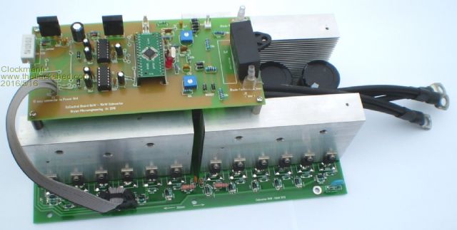
Everything is possible, just give me time. 3 HughP's 3.7m Wind T's (14 years). 5kW PV on 3 Trackers, (10 yrs). 21kW PV AC coupled SH GTI's. OzInverter created Grid. 1300ah 48v. |
||||
| gpalterpower Senior Member Joined: 19/07/2009 Location: AustraliaPosts: 175 |
That is Awesome Clockman. Impressed to say the least with all of your work! Been following your projects as well, and seems you caught the Inverter sickness early in the peace. Would be interesting to have a look a your book. Can it be purchased on line? I feel there is another project in the wind for me just waiting to be built,........but I better finish this one first before I start anything else. 
Marcus if it aint broke dont fix it!! |
||||
| Clockmanfr Guru Joined: 23/10/2015 Location: FrancePosts: 429 |
Hi Marcus, I just wanted an Inverter that worked, and did what it says. Sadly the so called Rolls Royce of Inverters was a catch all, once you had it you had to buy all there expensive gear to control it. Trading Standards Europe agreed and after 6 months I got my money back. At the same time oztules was messing with the PJ PCB boards and the New Toroids. I am no electronic wiz kid, but being a fool I can ask those silly questions. 'oztules' put up with me and I finished with a World beater of an 6kW OzInverter. However PJ played silly b.uggers with the 48v to 230vac boards. With some discussion, (actually I think 'oztules' loves a challenge) he headed off down the route of lets make our own Control Board, I did the 6kW-15kW power board, I used the good things from the PJ board, and re designed/modified the bad things. We are not beholden to any manufacturer any more. Now these Forums are great, but over the years, as folk die and Forums update or crash, that precious information is lost. So I did a book of my builds, at least my Boy's have a manual, and very importantly any one anywhere in the World now has the Info to do the whole machine, as I now include a supplement on the PCB's electronics. Hopefully very soon 'oztules' will be testing the new boards, sent some to him, once I am happy things are okay, then I will set up a link for the book, and contact all these Forum Moderators. Here is my latest MK6 OzControl Board, its simple, for folk like me, and its double sided, but the Blue tracks can be replaced with jumpers/0r/links, then its single sided for DIY at home etch 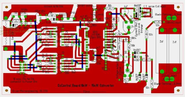
. Everything is possible, just give me time. 3 HughP's 3.7m Wind T's (14 years). 5kW PV on 3 Trackers, (10 yrs). 21kW PV AC coupled SH GTI's. OzInverter created Grid. 1300ah 48v. |
||||
| Clockmanfr Guru Joined: 23/10/2015 Location: FrancePosts: 429 |
Hmm, Image is not very clear. Everything is possible, just give me time. 3 HughP's 3.7m Wind T's (14 years). 5kW PV on 3 Trackers, (10 yrs). 21kW PV AC coupled SH GTI's. OzInverter created Grid. 1300ah 48v. |
||||
| Gizmo Admin Group Joined: 05/06/2004 Location: AustraliaPosts: 5078 |
GIF is best for this sort of thing. http://www.thebackshed.com/forum/help.asp#FAQ19 The best time to plant a tree was twenty years ago, the second best time is right now. JAQ |
||||
| Clockmanfr Guru Joined: 23/10/2015 Location: FrancePosts: 429 |
Thanks Gizmo, heres a GIF....... 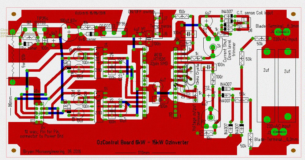
Everything is possible, just give me time. 3 HughP's 3.7m Wind T's (14 years). 5kW PV on 3 Trackers, (10 yrs). 21kW PV AC coupled SH GTI's. OzInverter created Grid. 1300ah 48v. |
||||
| gpalterpower Senior Member Joined: 19/07/2009 Location: AustraliaPosts: 175 |
Ah , much better Clockman. Im sure your book is just as clear and comprehensive as the circuit board above. I'm no electronic wizz either, but I do like a challenge from time to time. It certainly makes it easy with the guys on the forum. Definitely have some smart cookies here.  I'd be lost without them! I'll be asking a few dumb questions soon as I go deeper with my project but I'm preety sure I'll get plenty of help when needed. And that's the great thing about "The Back Shed".... everyones here to help each other. I'd be lost without them! I'll be asking a few dumb questions soon as I go deeper with my project but I'm preety sure I'll get plenty of help when needed. And that's the great thing about "The Back Shed".... everyones here to help each other.
I'll be looking forward to gazing thru your book. Marcus if it aint broke dont fix it!! |
||||
| Page 1 of 3 |
|||||