|

|
Forum Index : Electronics : inverter experiment pure sine EGS002
| Page 1 of 6 |
|||||
| Author | Message | ||||
oztules Guru Joined: 26/07/2007 Location: AustraliaPosts: 1686 |
This may interest those toying with making a low frequency pure sine inverter.. of whatever voltage you choose for input and output. This will be fairly brief, as it is experimental at this stage. This involves a EGS002 board which can be had for around the $7 mark on aliexpress and ebay. The test board looks like this.. a simple dual voltage output stage to keep the volts to 12v and 5v for the EGS002, with a transistor for the main step down voltage stage. The card, a CT etc. 
I made a quick h bridge to use for the initial test, but designed the control card to interface with the PJ power board.. it has the caps and heat sinks already. The down and dirty H bridge is this: ( your allowed to laugh) Once that found out a few flaws ( voltage regulator went west for no apparent reason ) we then plugged it into the PJ board. The PJ had only 1 mosfet per leg... now there's confidence ( less to replace ) like so: The fired it up, with a 40w load.. it was the only filament thing in the place....so it was pressed into service... Well it worked.. The voltage control went from 68acv to over 260vac. Transformer was 32:240v. The temp probe was heated up, and the unit stopped, restarted 8 seconds or so later, the current transformer will have to wait until I have it connected to the battery bank, and a big transformer attached. Suffice to say I was pleased to see it running at all.. didn't expect it to be so easy I must admit. Fets stayed cold ( touching the front of them, there was no heat...... so.... Put 2x 560r 20w ceramic resistors as well as the load. Unit started smoothly, constant frequency, and soft start voltage... straight to the 240v mark.... nice so far. Ran for a few minutes, until the load resistors started to smoke....checked the fets, and with 240 watts, the temp was barely warm on the front of the fets... so I guess that 600 or more watts on a single h bridge is well within reach... but my 56v power supply was topped out at 300w... so that will have to wait until I get it all better resourced. The wave looks like this: It didn't change even as I dropped the load on off on off etc.... until I got tired of trying to fool it. I am hoping that this translates into the high power phase as well, we'll see. It is looking promising. Next step is to put 6 fets on each leg, and see how the switching transitions degenerat, or if the drivers can handle it nicely without further conditioning... I live in hope.... but not confidence. I would prefer to use galvanically isolated supplies for the high side drivers, rather than the pump, and if this is necessary, will probably end up just buying the chips, and designing the power supply with pwm for the drives and logic separately. and then driving with high current totems.... but we'll see. .............oztules Village idiot...or... just another hack out of his depth |
||||
| Gizmo Admin Group Joined: 05/06/2004 Location: AustraliaPosts: 5078 |
Nice work Oz. I did order in one of the EGS002 boards, but haven't taken it any further yet. Glenn The best time to plant a tree was twenty years ago, the second best time is right now. JAQ |
||||
oztules Guru Joined: 26/07/2007 Location: AustraliaPosts: 1686 |
Problem i found is that the PJ works so well, that you lose the desire/drive to make another one.... the pj just works so well, there is little to improve ( the converted units like ours.... not the originals.....) I bet if you had not made a reliable PJ conversion, you would have done this already 
.............oztules Village idiot...or... just another hack out of his depth |
||||
oztules Guru Joined: 26/07/2007 Location: AustraliaPosts: 1686 |
Been very busy with other stuff, but got a chance to do a few hours with this thing. Wound a small 3kw torroid. put in another fet in the h bridge legs. we ended up with this little beauty. Thats an oven element with about 2100watts. The heat sinks stayed pretty cool over the 10 min test. voltage was stable... very stable. ..............oztules Village idiot...or... just another hack out of his depth |
||||
| Clockmanfr Guru Joined: 23/10/2015 Location: FrancePosts: 429 |
That looks like a nice circuit you have put together with that driver board. The PJ Board reliance does concern me, but now you are pushing the boundaries again, I can sleep a little bit better. My life has certainly changed, thanks to the 'oztules' endeavour's. 
PS, Book will be 84 pages, 100 odd colour photographs and drawings, A4 size, about 20,000 words. At present, mornings and evenings, when its dark, I am formatting the pages at page 41 today. Everything is possible, just give me time. 3 HughP's 3.7m Wind T's (14 years). 5kW PV on 3 Trackers, (10 yrs). 21kW PV AC coupled SH GTI's. OzInverter created Grid. 1300ah 48v. |
||||
| frwainscott Newbie Joined: 04/01/2016 Location: United StatesPosts: 3 |
I have A question that I could use some input on, If your using A 220 center tap transformer for 220 and two 110 circuits would you reference the 220 or 110 and if you reference the 110 which leg would you reference? I have A EGS002 board im going to start playing with as soon as I can find everything,since I just moved. Also, would it be more trouble than its worth to revamp a 12/24 volt board for 48 volts? Thanks..... Frank |
||||
oztules Guru Joined: 26/07/2007 Location: AustraliaPosts: 1686 |
Frank I would use the 220v as the reference. The boards have no preference for DC voltage. It is up to you to provide the 5v and the 12v for it's operation... thats all. So it is only your transformer and fets that have to match the load.. ie 48v is lower current fets, and higher voltage, and conversely fore 12 and 24v. You can in theory just use taps on the primary to go from 12 to 24 to 36 to 48 or 96 or whatever you want. As an aside, the current regulation using a torroid is dangerous to the fets. The EI transformers have enough leakage to sustain switching changes.. the torroids don't. So I had no trouble with the EI, but the torroid blew/exploded the fets the moment I fiddled the current pot to get it to limit. 
I may just end up buying the main chip and crystal, and go from there I think in the end..... not sure just yet... or maybe use a nano micro to take care of house keeping, and just use the board for pwm. .......oztules Village idiot...or... just another hack out of his depth |
||||
| frwainscott Newbie Joined: 04/01/2016 Location: United StatesPosts: 3 |
Oztules Thanks for the reply, im way in over my head here but after envisioning it in my head I could see that using the 220 for reference is the way to go. I need to find a program for experimenting so i dont waste so much time. Any suggestions? Thanks, ... Frank |
||||
| mason Regular Member Joined: 07/11/2015 Location: CanadaPosts: 86 |
Oztules, could you post what components you used for your simple dual voltage output stage circuit, for all the novice techs here. thanks Billy |
||||
| yahoo2 Guru Joined: 05/04/2011 Location: AustraliaPosts: 1166 |
there has been some interesting developments in the last few days testing the egs002 you can have a sneak peak, hoping oz will post it here once the dust settles. I'm confused, no wait... maybe I'm not... |
||||
oztules Guru Joined: 26/07/2007 Location: AustraliaPosts: 1686 |
Yes it is significant, and really a game changer for folks that want to roll their own. I have not seen anything that will surpass the performance now, even the big selectronics can do no better, and in fact worse with some loads that use phase switching..... and long run high power periods. Will get the story going here when it is further refined....I can't make it work any better, as it is everything I could ask for now, but I want to reduce it to it's minimum, and have no 002 board involved also, so it is independent of manufactures whims.... plug in chips, and a true remote area solution, where everything can be fixed on site easily ...........oztules Village idiot...or... just another hack out of his depth |
||||
oztules Guru Joined: 26/07/2007 Location: AustraliaPosts: 1686 |
I forgot to give mason the stuff he asked for.... try this: well that didn't work as it is a png file so go here: http://www.anotherpower.com/board/index.php/topic,1116.msg11457.html#msg11457 ...........oztules Village idiot...or... just another hack out of his depth |
||||
| mason Regular Member Joined: 07/11/2015 Location: CanadaPosts: 86 |
Oztules, thanks for sharing all your work. Mason |
||||
| yahoo2 Guru Joined: 05/04/2011 Location: AustraliaPosts: 1166 |
 Oz, reading your egs002 thread on anotherpower, I am interested in the comments about the 4110 fets (mainly because I am avoiding having a go at building the PCB Oz, reading your egs002 thread on anotherpower, I am interested in the comments about the 4110 fets (mainly because I am avoiding having a go at building the PCB  ) )
How are you testing the aftermarket TO-220 4110 fet? Is it a precise test to grade them into matched sets or just weed out the real smokies. are you passing 10 amps @ ?? volts and measuring the RDS ON mOhm value with the fet cold? 20A @ 5V ? 10A @ 97V for a voltage test? I have seen some old tests on genuine IRFB4110 Fets, 20 amps @ 5Volts and let the case temperature settle at 86C after a few minutes. They all measured very close to 15 mOhm. I assume you haven't made a test jig and it is alligator clips or clamps to hook-up the fet. Do they come in a static bag when you get them? I'm confused, no wait... maybe I'm not... |
||||
oztules Guru Joined: 26/07/2007 Location: AustraliaPosts: 1686 |
Sorry Mason, didn't see this Yes 10A with gate source of 12v and measure the mv and calculate. It is a quick test to sort same with same. Should get 3-4mo.... usually 3-6mo. Voltage has never been an issue and don't test for it. I use the old computer power supplies converted for current and voltage. Village idiot...or... just another hack out of his depth |
||||
oztules Guru Joined: 26/07/2007 Location: AustraliaPosts: 1686 |
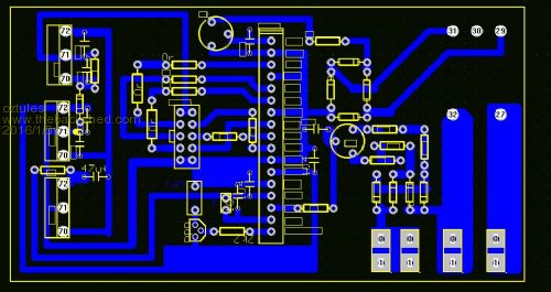
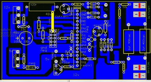
Pic of todays paper print out for the board etch Then the copper with pattern from the kinston Then the boards ( twin ) and the back and the pcb in the program 
Worked first up... always good. Simply amazed at the simplicity of these things, and the sheer power you can call up if you have the fets and transformer to suit.... very solid so far after week or more running the house. Two hrs a day at at lest 2.5kw, surges of over 7kw ( seen 9kw too). How they can be so simple and work so well I don't know. Next step is only the 8010 and board to suit. BOM from the program may help "","SPADE","4","A91 A92 A93 A94" "0r","AXIAL0.3","3","A60 A62 A63" "0r","AXIAL0.4","2","A48 A49" "100uf 100v","RB.2/.4","1","A6" "104","C2","1","A51" "10PIN","10PIN","1","A73" "10PIN","17PINA","1","A88" "10k","AXIAL0.3","2","A5 A72" "10k","AXIAL0.4","1","A10" "10k","POT","1","A1" "120r","5WRESIST","1","A13" "13v","D2","1","A65" "1k","AXIAL0.3","1","A55" "2k","POT","1","A54" "2k2","AXIAL0.3","1","A50" "2uf 400vac","AXIAL1.0","2","A11 A12" "35c","TO220V","1","A66" "4u7","2PINCAP","3","A3 A14 A15" "4u7","C2","1","A53" "50k","AXIAL0.3","4","A82 A83 A84 A85" "5v6","DIODE0.4","1","A4" "fr107","D2","8","A56 A57 A58 A59 A61 A78 A79 A80" "npn","TO92","1","A2" "tip35c","TO220V","1","A68" Hope this helps someone ..............oztules Village idiot...or... just another hack out of his depth |
||||
oztules Guru Joined: 26/07/2007 Location: AustraliaPosts: 1686 |
And now to try the pdf???.... no did not work.. so try here: http://www.anotherpower.com/board/index.php/topic,1116.msg11541.html#msg11541 .........oztules ps sorry Mason, it was Yahoo I meant to reply to ..... Village idiot...or... just another hack out of his depth |
||||
| mason Regular Member Joined: 07/11/2015 Location: CanadaPosts: 86 |
No Prob Oztules, Question for you, the two blue wires are they coming from your toroid transformer? Mason |
||||
oztules Guru Joined: 26/07/2007 Location: AustraliaPosts: 1686 |
Yes, they provide a 240v sample for the cpu to determine the amplitude of the wave form. There are two pins for the current transformer torroid that are not being used in this bench test, as need a kw or two to trigger the lowest setting with this circuit... easily changeable to lower if needed.... seen it at 9kw too. 48v comes from the fet card. Pinout for the 10 pin plug goes directly into a PJ card....but MUST change the gate resistors from 50ohm to 5r6 and use reverse diode , or the fets will heat up wickedly. With that change, then the fets stay very cool for 0-500w, warm up to 2kw, but really needs my fan circuit, or in this case, a 12v fan running at 5v silent and slow, and then runs at 25c-30c even at 3kw and more continuous ( 2hrs etc). If your transformer is torroid... the MUST REMOVE the LM393 from the 002, short pins 7 to 8, and then short pins 1 to 4.... Failure to do so will blow the fets to hell and back whenever the current sense is activated. A big EI will survive, but a big torroid will blow it all up if you leave the 393 there. .............oztules Village idiot...or... just another hack out of his depth |
||||
| Clockmanfr Guru Joined: 23/10/2015 Location: FrancePosts: 429 |
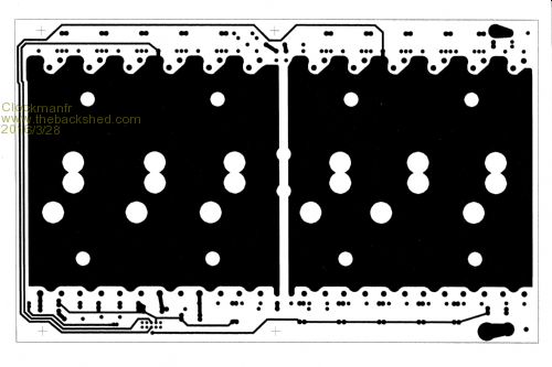
I will see if this works here...? The New 6kw-15kW Power Board that will match the New 8010 OzControl Board.... 
Everything is possible, just give me time. 3 HughP's 3.7m Wind T's (14 years). 5kW PV on 3 Trackers, (10 yrs). 21kW PV AC coupled SH GTI's. OzInverter created Grid. 1300ah 48v. |
||||
| Page 1 of 6 |
|||||