
|

|
Forum Index : Other Stuff : Making my own CNC plotter
| Page 1 of 3 |
|||||
| Author | Message | ||||
Prime_8 Regular Member Joined: 07/12/2014 Location: CanadaPosts: 51 |
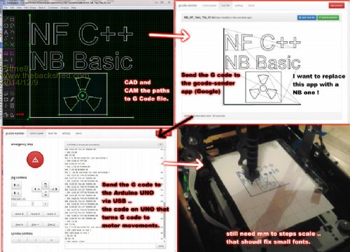
Making my own CNC plotter eventually the G code sender app( PC side ) and the sketch on the UNO . I my try one of the open source G code interpreters for Arduino . I'll edit more info on here later. once I get this lil' thing working i will up the size thanks to some treasures ando sent me . 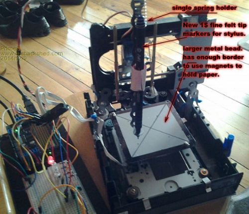
Old coder, and bodger of things that may spark. |
||||
| Pete Locke Senior Member Joined: 26/06/2013 Location: New ZealandPosts: 181 |
Waaaaaaayyyy back in the day, even before the Sinclair ZX81, I went to an electronics show where an X,Y plotter was being demonstrated. It would plot on A3 paper with felt tip pens. Four pens which had a cap put back on them when they were done with by the plotter. It used an electrostatic charge on the base to hold the paper in place. Magnets might be a lot easier  |
||||
Prime_8 Regular Member Joined: 07/12/2014 Location: CanadaPosts: 51 |
lol . the first printer I ever had at home ( i would love for the parts rite now ) was a noisy dot matrix thing on my vic20 . the larger bed and a few other zip ties has mad eteh thing more rigid so it is working better . enough for me to move back to teh code side of things . i have found that i get 255 steps in single mode and 255*16 steps in micro-stepping . micro stepping is a bit slower . lol. also the motor controller shield I use is I2C ~ set to run at 400khz. I hope to edit the sketch to allow for steps per mm . then I will support both stepping modes , using custom commands . as it is now you can send a Q_ code to change step modes . and the steps per mm seem to be working but I ran out of time tonight to fine tune the true values of steps/mm for both modes. my measurements must be off for single step , as when i put in value for full X travel less 1 step it went well past by about 4 steps but the micro-step mode , is 4080 steps for x and y . would be nice if i had a burning laser, as the plot is very smooth . heheh . I have a few CDRW diodes , but no driver for them . I think the error may be that I have to mix integer steps with float values, but I'll know more later . I'l probably start work on the preview rendering code too soon . last video : http://youtu.be/TMKj_8VU0w8 Old coder, and bodger of things that may spark. |
||||
Downwind Guru Joined: 09/09/2009 Location: AustraliaPosts: 2333 |
Hey im all about building your own stuff, but do you realize you can buy a 3 axis board from China on ebay for about $50.00, that has it all built in, micro stepping, motor drivers, the full works. Its what many of has used for a CNC driver board, which your plotter is a basic form of. What i found was its better to put the time and $$ into building a good hardware based structure and simply buy a controller board from China. Im more than able to build my own driver boards, but why bother when parts cost more than i can purchase a full 3 axis board for. Pete. Sometimes it just works |
||||
Prime_8 Regular Member Joined: 07/12/2014 Location: CanadaPosts: 51 |
no fun in just buying stuff. (well ok , but not as much for me LOL) i have looked at all sorts of controller boards and kits . I will probably get a dedicated one later, but not a big interest for me rite now. same reason I code my own soft-wear , the fun and challenge , and I can build it how I want . With what i have and can afford /recycle . i have fonts sorted and mm dimensions sorted. 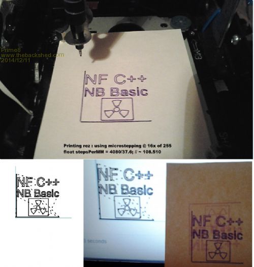 Old coder, and bodger of things that may spark. |
||||
| ando Newbie Joined: 05/12/2014 Location: AustraliaPosts: 6 |
Lookin good Prime, I see you have your prototype franken-plotter running smooth and accurate now. Hey Prime, do you need any toothed belts? I've got a bunch of spares here. And the other day I picked up 4 more all in one printer/scanners dirt cheap. I only pulled 2 apart so far. One only had 3 dc motors, the other had 3 steppers and 1 dc. I never know what I will find. It's like openning crissy pressies.  |
||||
Prime_8 Regular Member Joined: 07/12/2014 Location: CanadaPosts: 51 |
franken plotter is stiffer and more square ( still all temporarily tied and bolted ). the non micro-stepped movements seem to cause fonts and small things to get wrong. so I have to look at what could be causing that . Its not losing steps , and it still homes and moves to exact coords fine . could just be a resolution limit . this would be sick with a engraving / cutting laser! Thanks man ! ++ lol yeah , love re-purposing old printers . + i can better sort the parts at the disposal / dump recycle stations . i took one apart that was all simple dc motors with encoders . if i had a arduino that had more interrupts pins, then i could use some of my high power servos. toothed belts and pinion sets , or drive sets are handy. :: ps have you thought of using servos for your telescope? they are fast and strong and not to hard to make them full turning if you have old ones in your goodies pile / box. I have loads of high torque servos , but I need a rotary encoder that can track turns and report turn count to the arduino . ~ so that's a project for next summer . Old coder, and bodger of things that may spark. |
||||
| Gordz Regular Member Joined: 10/08/2013 Location: AustraliaPosts: 55 |
Keep your eye open for old ink jet printers. They will usually have at least one high resolution rotary optical encoder which will give you a great quadrature signal output. Use that on your final driven gear or shaft, a toothed belt and reduction hearing and you have cheap high precision positioning. |
||||
Prime_8 Regular Member Joined: 07/12/2014 Location: CanadaPosts: 51 |
thanks Gordz , i have a few . problem is : 1 i need to figure out what they output ( bit pattern ) . its not hard to trial and error it . 2 number of pins consumed ( I have a UNO ) . I could get a Mega soon any how so that will drop away . I wonder if Arduino UNO or Mega is fast enough to read them . I have 1 rite now. ( 4 pin ) what I would like is a I2C sensor that counts pulses, and returns pulse count . that way it would store the current position. Some I2C magnetic sensors will return a angle , so one could track that some how. on a other note : I tested an other simple & cheap way to make 'rails' . it works quite well for first version . I have to hook up the driver card to test it . 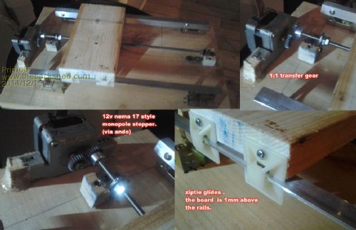
In new year I may order a complete laser for the rig . not too expensive, from online. Old coder, and bodger of things that may spark. |
||||
| Gordz Regular Member Joined: 10/08/2013 Location: AustraliaPosts: 55 |
The sensors output "quadrature" data which is a two bit representation of direction. Although you can use a simple look up table to figure out what's happening, and you can measure pulse width to calculate speed it is easier to use a PIC micro or similar which has built in QEI. You may find there is a 'sketch' available for this but I do not use any of the 'duino range. Having said that if you program in C it is easy enough to convert the code. It will be well worth the effort. |
||||
| Gordz Regular Member Joined: 10/08/2013 Location: AustraliaPosts: 55 |
I started a post with a bit of info on quadrature information FYI. |
||||
Prime_8 Regular Member Joined: 07/12/2014 Location: CanadaPosts: 51 |
cheers . i have 2 nano's coming . i may just temp use one to read and process data and serve it up over I2C back to the main board . what im looking for is a cheap system that can use magnetic sensors . like these guys use . http://youtu.be/UTfDSjZyG78 they use servos in winch mode and magnetic position trackers for closed loop . their code is opensource . i have literally buckets of R/C servos from ones from ultra UM to a few the size of a few 9V batteries stacked. in there rig they are using what looks like just standard size servos in endless turn mode or have been modded to work that way . the key they have is they get a deg' reading on lead screw position . and all the speed and power of servos. PS happy holidays all. Old coder, and bodger of things that may spark. |
||||
| plasma Guru Joined: 08/04/2012 Location: GermanyPosts: 437 |
aha, another Nuclear user here :) Welcome prime_8 the idea to create the software with NB / NF is cool , cant wait to see your Progress. i wonder about the ziptie glides and the use of wood , because iam think this isnt a good solution. maybe it works some time but i think some ballbearings and a V shaped rail are much better. linear glide with vshape 
|
||||
Prime_8 Regular Member Joined: 07/12/2014 Location: CanadaPosts: 51 |
yeah a v rail is way better , especially if the rig has to hold a bunch of mass. i could also use brass bushings or DELRINŽ if i could find my scraps. I have roller bearing rails but i need my beefier drivers to start that rig. For those who may have seen my R/C aircraft designs and build will know i like to re purpose cheap and common things. 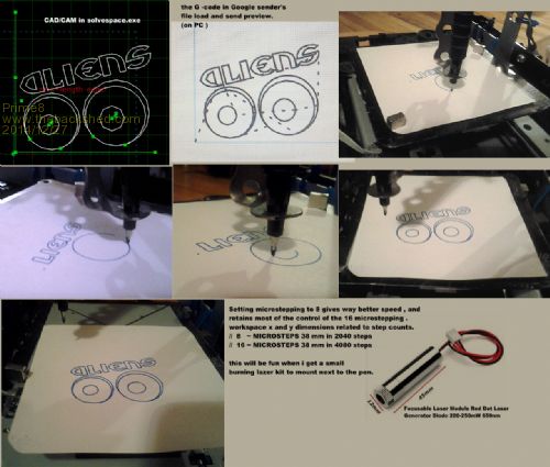
Old coder, and bodger of things that may spark. |
||||
Prime_8 Regular Member Joined: 07/12/2014 Location: CanadaPosts: 51 |
dang laser&driver combo got back order . ( i'm pretty sure I can import 200mw lasers here ). I know other countries have output wattage limitations / usage restrictions. Old coder, and bodger of things that may spark. |
||||
Prime_8 Regular Member Joined: 07/12/2014 Location: CanadaPosts: 51 |
scored 2 more sets of draw slides with bearings . I have some beefier stepper drivers on the way for bipolar steppers. I have to solder the headers on my last controller I have now so I can swap out the Z axis servo for a 3rd CDROM stepper. thanks to Ando I have a 36V rotary tool motor and all I need to hold any of my tool tips. I also have a small 5v ? one . but it has a funny head and flywheel. In the end I need some more parts to arrive before I can scale it up . The issue i have now is that the motor driver boards i have , the good ones are for development , and use I2C for comms , so max out at 400khz , that's not fast enough when you factor the protocol over head. I have some boards coming that just use ENB STP and DIR pins. i'm looking for quadrature sensors , or magnetic PWM , as i can setup a Arduino Mega to read them fast enough to use servos. later I will convert some of my scrap cordless screwdrivers to servos/gear motors. just needs a set of 3 for that , but that is a experiment for a later day . tonight I must solder. LOL Old coder, and bodger of things that may spark. |
||||
Prime_8 Regular Member Joined: 07/12/2014 Location: CanadaPosts: 51 |
ok most of the soldering is done . i now have 3 steppers working . I used the smaller one from a floppy drive. ( one form ando ) With the rig as it is have room / driver space for : 2 servos 2 DC motors or 1 more stepper the focal point of the laser can be adjusted for by using a fine stepper on Z axis. i need to make a mount point and JB weld it to the old read head mount / sled. I have been using old IDE cable and the end to make it so it all uses bread board jumpers for now. I have found i can speed up the rig even when micro stepping is in use. via code i can set micro stepping values. I hope to use a small R/C brushless motor on the servo port 2, as it has crazy torque and can hit crazy high RPM with very good speed control via PWM and the ESC. The ESC has a BEC the has a rock solid 5V out , so i could run the logic and all from one of my big battery packs if I chose. ( portable rig ) rite now it is set so that all Z axis movements have to happen before any XY deltas. I hope to sort out a 3D line algo that will work as I want . any how very fun . 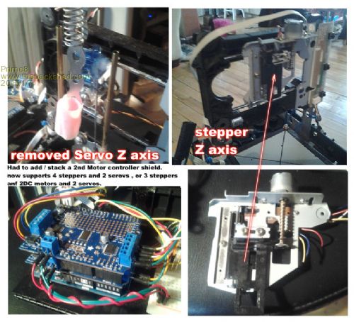
Old coder, and bodger of things that may spark. |
||||
| plasma Guru Joined: 08/04/2012 Location: GermanyPosts: 437 |
make video please , the pics are to small . |
||||
Prime_8 Regular Member Joined: 07/12/2014 Location: CanadaPosts: 51 |
will do , seems the site here shrinks the pics ? ah well i'll post em some place else and link for higher rez . most places you can right click and open in new tab to see at full rez? I did a video this am but all i had available was my cell cam pic test no water mark . to see if the water marker is re-sizing images. I'll up load the video to you tube in a few min . ignore the 3 led's they are not hooked up yet , nor is the 3 tac buttons . I need my female headers for the top motor shield to put them back on . when i get my good camera charged up and running again i will get soem better macro shots and video . My tablet is pretty good too but needs daylight or flood lights almost to get nice video . nuts it got re-sized. i will try picpaste.com try from here :  Old coder, and bodger of things that may spark. |
||||
Prime_8 Regular Member Joined: 07/12/2014 Location: CanadaPosts: 51 |
hmm seems the link to the big pic died. here it is , but these forums will shrink it . 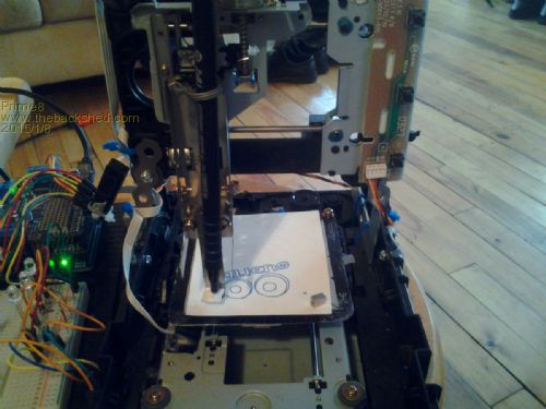
here it is running , no edits for time , just 1:1 speed at just 8x micro stepping . the video : http://youtu.be/-xaNdzn2P_o sorry all i had was my cell and it was early so its a bit blurry . I send G code to mu rig with this chrome app , for now. I will have my own one built soon . chrome G code sender app ( free ) Old coder, and bodger of things that may spark. |
||||
| Page 1 of 3 |
|||||