|

|
Forum Index : Microcontroller and PC projects : pickit3 troubles
| Page 1 of 3 |
|||||
| Author | Message | ||||
Bryan1 Guru Joined: 22/02/2006 Location: AustraliaPosts: 1345 |
G'day Guy's, Been trying to finally program the micromite and aint having much joy. I have now set up the breadboard twice and ensured all connections are true. Put a brandnew pic in and no problems with IPE seeing the chip so program the chip and works fine. Go to try and read and get an error, then when I tried to verify I got Verifying boot config memory Address 1fc00000 Expected value f010d870 Received Value 4010a6000 I set the pic up run along with the RX/TX pins connected to my scanalogic analyzer and no activity when the pic is booted. So tried again with my fluke 865 on scopeview and the voltage on pin11 was 2.49 volts but no Hz. On the output window it does show hex code starting at 0x5000 too. Why I'm getting that error has me stuffed and I did try that fidi based usb/serial dongle with 1k resistors and on 2 computers no output to teraterm. Regards Bryan |
||||
Grogster Admin Group Joined: 31/12/2012 Location: New ZealandPosts: 9308 |
So, you are saying that the VERIFY fails, but the device DOES program OK? Forgetting the verify stage just for the moment, once programmed, can you use the chip as a MicroMite? I sometimes got odd things with the verify too - I just ignored them, cos so long as the device programmed OK, it always seemed to work... I'm not saying that you don't have an issue here, but provided it programs OK, then I tend to ignore the verify - but that's just me. Smoke makes things work. When the smoke gets out, it stops! |
||||
| WhiteWizzard Guru Joined: 05/04/2013 Location: United KingdomPosts: 2817 |
Bryan, Three initial questions: 1> Are you using a PIC32MX150… or PIC32MX250… ? 2> Do you have a 47uF (or similar) connected to Vcap? (Check polarity) 3> Do you have a USB-to-Uart Module at hand for further testing? We should be able to sort you out if we step through things to check . . . For everything Micromite visit micromite.org Direct Email: whitewizzard@micromite.o |
||||
| WhiteWizzard Guru Joined: 05/04/2013 Location: United KingdomPosts: 2817 |
Please confirm how you are powering the PIC. If its from a FTDI module then please measure voltage output (when connected to PIC). Are you supplying ALL power inputs to the PIC? Pins 1, 13, 28 to +3v3. Pins 8, 19, 27 to 0v. DO NOT connect Pin 20 (Vcap) to +3v3. This pin only goes to 47uF cap +ve. Ensure Tx of FTDI module goes to PIC Rx (pin 12). Ensure Rx of FTDI module goes to PIC Tx (pin 11). Labelling on the FTDI module can sometimes be the FTDI Module's perspective, OR sometimes the connected device perspective. Get it wrong and nothing will appear to work!! Can you take a photo of your set-up and post it (assuming none of the above fixes your issue. For everything Micromite visit micromite.org Direct Email: whitewizzard@micromite.o |
||||
Grogster Admin Group Joined: 31/12/2012 Location: New ZealandPosts: 9308 |
...Gandalf(the WhiteWizard) makes some good points there, and worth checking before we get to carried away. I always prefer external power in the form of regulated power-packs. Although, the MicroMite chip should be perfectly happy on USB power with a LDO regulator in front of it... Smoke makes things work. When the smoke gets out, it stops! |
||||
Bryan1 Guru Joined: 22/02/2006 Location: AustraliaPosts: 1345 |
The pic's I used are the pic32mx150F128B-50 and the -1 chips. Yes I have a 47uf tantalum cap fitted Ok connected that US232B to the rx/tx pins along with 1K resistors in series and the prompt just moved on one space. Did several re-connects and got the same thing. So took the 1K resistors off and did a direct connection. This was the output with 3 re-connects 1st. /ýc~ô)*ïy÷y_r 2nd. /¯ý;ÚCHÔíi¿Þ*ïy÷y_r 3rd. /¯=:9÷ïõ+*ïy÷y_r/¯=:9÷ïõ+*ïy÷y_r So it does look like that US232B serial dongle may be the trouble and I do have one coming I got off fleabay. I have used Kalex before and the shipping is great so hopefully it may be at the P.O. today. Regards Bryan |
||||
| WhiteWizzard Guru Joined: 05/04/2013 Location: United KingdomPosts: 2817 |
Ensure Baud rate of TeraTerm is 38400 and NOT 9600 which it defaults to! That may be your issue from what you describe. For everything Micromite visit micromite.org Direct Email: whitewizzard@micromite.o |
||||
Bryan1 Guru Joined: 22/02/2006 Location: AustraliaPosts: 1345 |
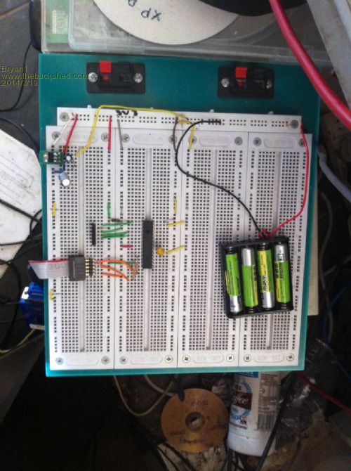
Hi WW, Yea I did have the baud rate set to 9600 so changed it to 38400 and got this ÿµÿþ¿ÿãúÿüÿþÿóþ=ýïÿÿýö This is with 1K resistors in place. Now as you asked a pic of the Breadboard 
At the top left is the 3V3 power supply comprising of a TLV11173v3 reg with caps which go to the left top rail. The right top rail is for the 4 AAA's I use as the power supply. I have checked every power and gnd connection and everything is true. |
||||
| WhiteWizzard Guru Joined: 05/04/2013 Location: United KingdomPosts: 2817 |
Ok lets test the FTDI module next. Disconnect the PIC from the FTDI module. Connect Tx and Rx together on the FTDI module. Fire up TeraTerm at 38400 and start typing. Do the characters you type appear on the screen? For everything Micromite visit micromite.org Direct Email: whitewizzard@micromite.o |
||||
Bryan1 Guru Joined: 22/02/2006 Location: AustraliaPosts: 1345 |
Hi WW, Connected rx/tx together and yep what I typed showed up in teraterm. Now off to the PO to send a letter and see if that kalex dongle has arrived. |
||||
Grogster Admin Group Joined: 31/12/2012 Location: New ZealandPosts: 9308 |
Do you have 10k resistor on pin1 for programming/verify? Check manual, page 4... Once programmed, pin1 then is connected to pin28.(bypassing 10k resistor) That looks to me like classic baud-rate settings wrong or inverted data. One assumes that the USB serial port thing will take care of inverting the data for you, so you need to make sure port is 38400, 8N1 in TT. QUESTION: Have you used the same USB serial adaptor on anything else to verify that it is OK and not crook? Smoke makes things work. When the smoke gets out, it stops! |
||||
Bryan1 Guru Joined: 22/02/2006 Location: AustraliaPosts: 1345 |
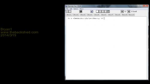
Hi Guy's, Well no new dongle at the PO and as Grogster has said it does look like the data isn't being inverted. Now for the first time I got the pic connected to MMChat and below is the output. 
So now off to the shed to hook up an inverter chip and see if that makes a difference. |
||||
Grogster Admin Group Joined: 31/12/2012 Location: New ZealandPosts: 9308 |
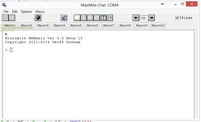
MMChat works fine for my MicroMites, provided you set the port up correct. 
At this point, I have to agree with the Wizzard, and be very suspicious of the USB serial lead. My example photo above, is using one of his 44-pin boards, but he has intergrated the USB serial port on the PCB, but this is still my results via USB. Smoke makes things work. When the smoke gets out, it stops! |
||||
| WhiteWizzard Guru Joined: 05/04/2013 Location: United KingdomPosts: 2817 |
Bryan, In my last test I asked you to do (shorting Tx & Rx) you said you got the characters typed appearing on screen. Please can you confirm this again AND then remove the short. Do the characters stop appearing now (i.e. confirming no local echo switched on). Please update with outcome . . . For everything Micromite visit micromite.org Direct Email: whitewizzard@micromite.o |
||||
| WhiteWizzard Guru Joined: 05/04/2013 Location: United KingdomPosts: 2817 |
If the characters stop appearing in my previous test, then this proves FTDI module ok and that the chances are (assuming no missing ground connections) that the output is inverted. You can use a simple transistor inverter if you don't have any inverter chips. One last thing to try would be to reprogram the PIC again I had some strange behaviour once on a 28pin PIC which resolved itself once I re-programmed it). Keep us updated! For everything Micromite visit micromite.org Direct Email: whitewizzard@micromite.o |
||||
| WhiteWizzard Guru Joined: 05/04/2013 Location: United KingdomPosts: 2817 |
Another quick question - do you have any more PICs there to try? Maybe a 'damaged' pin on PIC Tx so another PIC could help eliminate this potential cause. For everything Micromite visit micromite.org Direct Email: whitewizzard@micromite.o |
||||
Bryan1 Guru Joined: 22/02/2006 Location: AustraliaPosts: 1345 |
Hi WW, Ok got a 74ls04 chip hooked up and now no output to teraterm or MMChat. I tried in my shed with the fluke and the inverter is working too. I tried on this computer too and programmed a new pic with the same result. So it does look like I'll have to wait for that new one to turnup. The pic's I'm using are pic32MX150F128B-50 too. When I shorted out the usb output I did get characters echoed and when I did a reboot I got that garbled text in MMChat. This was before I put the inverter chip in. |
||||
| WhiteWizzard Guru Joined: 05/04/2013 Location: United KingdomPosts: 2817 |
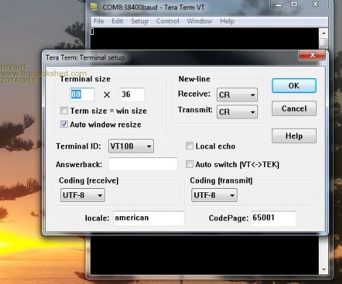
One last thing worth trying: In TeraTerm, select 'Setup' tab, then 'Terminal'. Can you please grab a screen shot of those settings and post it? Thanks . . . For everything Micromite visit micromite.org Direct Email: whitewizzard@micromite.o |
||||
Bryan1 Guru Joined: 22/02/2006 Location: AustraliaPosts: 1345 |
Hi WW, As requested here's that screenshot 
Now I put another inverter in this time a 74HC04 and on doing voltage checks found the output from the serial dongle on pin3 was -2.49 volts. I am running the inverter off the 3v3 rail too as I found when setting it up on the Vin rail the output was 5 volts. |
||||
TassyJim Guru Joined: 07/08/2011 Location: AustraliaPosts: 6102 |
Bryan, In your photo, it looks like you are using a USB to serial converter, not a USB to TTL. The blue thing-a-me-jig almost hidden with an IDC cable coming of it. If your converter has a moulded plug with a DB9 connector on it, it is RS232 serial and not TTL so inverters are needed. A photo of your adapter will confirm this. Jim VK7JH MMedit  MMBasic Help |
||||
| Page 1 of 3 |
|||||