|

|
Forum Index : Microcontroller and PC projects : DS3231 code mmbasic
| Page 1 of 3 |
|||||
| Author | Message | ||||
| atmega8 Guru Joined: 19/11/2013 Location: GermanyPosts: 722 |
Hello, has anyone a working DS3231 code for micromite? Would be nice if you could post it here. Thanks |
||||
| jwettroth Regular Member Joined: 02/08/2011 Location: United StatesPosts: 71 |
I'm working on one. Should have it done over the weekend and will post. John Wettroth |
||||
jman Guru Joined: 12/06/2011 Location: New ZealandPosts: 711 |
Hi The DS3231 has the same address and register layout as the DS1307 there is code in the forums to use the DS1307 I have attached code that will run on the uMite Regards Jman2014-03-07_195259_umiteDs1307.zip |
||||
| jwettroth Regular Member Joined: 02/08/2011 Location: United StatesPosts: 71 |
jman- this is partially true- the first 6 registers for basic time are the same. The configuration registers, alalmr registers and all the other special goodies are different. Bascially, all the things that make the DS3231 unique over the DS1307 are at higher addresses (these are just RAM in the 1307 which isn't present in the DS3231). I will start with that 1307 code but plan to expand on it signficantly. I'm especially looking forward to using the alarms- I want to put the micromite to sleep and have an alarm or timer tick wake it up. Another cool feature is that the DS3231 has an internal temperature register in it. I'm going to read out and display that value and use a DS18B20 for external temp. The project is just sort of a battery operated desk clock with internal and external temp that never needs setting. Thanks for the link- the DS3231 is a pretty cool part. Stay tuned. John Wettroth |
||||
| BobD Guru Joined: 07/12/2011 Location: AustraliaPosts: 935 |
Here is some code to read and interpret the temperature and Aging Offset register functions of the DS3231 If RTCdata(17) < &h80 Then
Temperature = RTCdata(17) + (RTCdata(18) / 256) Else Temperature = -(((RTCdata(17) Xor &hFF) + 1) + (RTCdata(18) / 256)) EndIf t$=Format$(Temperature,"%+6.2f") Print "Temperature is "; T$; "degrees Celsius" If RTCdata(16) < &h80 then Offset = RTCdata(16) Else Offset = -((RTCdata(16) Xor &hFF) +1) Endif Print "The Aging Offset data is "; Offset disclaimer: This is Maximite code written several years back. It may be different for MicroMite. |
||||
Grogster Admin Group Joined: 31/12/2012 Location: New ZealandPosts: 9308 |
My 3231 + EEPROM modules arrived last week, so I must hook one up and try it. It will be a chance to play with both devices on the I2C bus, and also test out Beta 10, where Geoff removed the slew rate to fix a bug, and see if this causes any problems. However, I would be inclined to second-guess any faults, as I am only a novice with I2C. I will see if I can find time to do this over the weekend some time. Smoke makes things work. When the smoke gets out, it stops! |
||||
| BobD Guru Joined: 07/12/2011 Location: AustraliaPosts: 935 |
I also have the DS3231 with EEPROM and I intend to store the Aging Offset in the EEPROM with the idea to retrieve it and reload it if necessary. I hope to experiment to see if a correction can be applied to achieve better accuracy. I have a bit of work ahead, my MM has been powered off for about 18 months and I am not (yet) into the MicroMite. |
||||
| jwettroth Regular Member Joined: 02/08/2011 Location: United StatesPosts: 71 |
Bob, Let me know what you learn and if you run into problems. John John Wettroth |
||||
Grogster Admin Group Joined: 31/12/2012 Location: New ZealandPosts: 9308 |
I'm lost already with the I2C. How do you specify the read-write address in the device? This is NOT the slave-address for the device, but the actual registers that you want to alter within the device? Do I just send two bytes? Byte 1 is the register, and byte 2 is the data to be written to that register? At this stage, just trying to write $00(h00) into address $0E on the 3231, which is the square-wave output. By default and without battery, it is 32kHz, but if you write $00 into address $0E on the 3231, this output changes to 1Hz, which I have an LED connected to. I DID get this working in PICAXE basic a year or two ago, but not sure how to port this to the uM... PICAXE code was: 'DS3232 tester 1A #picaxe 40x2 #no_table #no_data symbol x=b1 symbol key=b2 symbol video=D.2 hi2csetup i2cmaster,%11010000,i2cfast,i2cbyte 'Configure I2C for RTC communications wait 5 'Allow LCD screen to fire up serout video,T9600_8,("Talking to clock...",CR,CR) hi2cout $0E,($00) 'Set RTC to pulse LED at 1Hz serout video,T9600_8,("Done.",CR) end Things don't jive here. With PICAXE, you specify the start read/write address within the device, then the byte(s) to write. MMBasic does not allow for specifying a read/write address within the device for your data, so how do you specify that? Hello MOBI.  Yes, confused already... Yes, confused already...
EDIT: Have been reading through the code example for MM posted in the link above, but still can't see how you can specify a register address to read or write to within any given device. This MUST be possible, I am just not seeing it, as EEPROM memory is a fine example of needing to read/write to different memory addresses. Smoke makes things work. When the smoke gets out, it stops! |
||||
TassyJim Guru Joined: 07/08/2011 Location: AustraliaPosts: 6102 |
It all depends on the device. For the BMP085 pressure transducer, I do the following: I2C write BMP085address, 0, 2, BMP085control, BMP085temp
pause 5 I2C write BMP085address, 0, 1, BMP085reading I2C read BMP085address, 0, 2, BMPData(0) The first line sends the 'control byte' followed by the control I want to send we wait for the conversion to happen then send the message that we want to read Finally we read the two bytes of data into the array. I haven't tried an EEPROM yet but usually you will send 1 or 2 bytes for the address followed by one or more data bytes. The EEPROM usually auto increments the write address. The ones I will be playing with allow 64 bytes to be written at once. Jim VK7JH MMedit MMBasic Help |
||||
Grogster Admin Group Joined: 31/12/2012 Location: New ZealandPosts: 9308 |
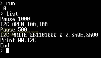
WORKING! 
I have my 1Hz blinking LED on the SQW output pin. 
Will post code etc in a moment...... EDIT: OK, here is a screenshot of the code on the uM: 
I started reading my way through the datasheet for the 3231, and naturally enough - it was all explained there - funny that.... 
In the case of the 3231, you send the slave address byte, followed by a register address byte, followed by the data you want to read or write to that register. Above code sets register $0E to $00, which causes the SQW output to oscillate at 1Hz for my "Ticking" LED. Smoke makes things work. When the smoke gets out, it stops! |
||||
| MOBI Guru Joined: 02/12/2012 Location: AustraliaPosts: 819 |
Hi Grogster, ===== edit- it looks like we were working in parallel ====== one step at a time. First thing to remember is the device address for MM Basic is a 7 bit address not 8 bit like the picaxe. MM i2c uses bits 1 to 7 only and leaves bit 0 as a data direction bit called read/write, where a 0 is write to slave and a 1 is read from the slave. So, as far as the device address is concerned, call bit 1 bit 0 and so on. You will probably find it easier to use binary address form e.g. &b0011100 in MM would have been &b00111000 (8 bits) in PICaxe. The next thing to remember is that the i2c slave has a number of internal registers or addresses usually starting at zero. Each register has a device specific function. In the RTC, address 0 is the seconds register that you can read from or write to (set time). If we want to read the seconds data, we first have to write a start address of zero. Subsequent reads will read from the next address (minutes) etc. MaxiMite allowed us to specify the start address as part of the read routine, but not in uMite. To do anything on the i2c bus, you first must activate or open the i2c function. You do this by the command i2c open,100,100. Never mind the reason for now, just use it. So, if you want to read the seconds, first point to the seconds (zero) register: i2c write device_address,0,1,0 where i2c write specifies data direction (master to slave). device_address is the 7 bit address, 0 is a special MM control. Just use it, don't try and understand yet, 1 says you have 1 byte to send, and 0 is the device register byte you want to access (in this case RTC seconds) i2c read device_address,0,1,value where i2c read specifies the data direction (slave to master) device_address is the same 7 bit address, 0 is the same MM control, 1 is the number of bytes to receive, and value is the variable you want the received data to appear in. In this case, it could be Secs. There is a special MM value called MM.i2c which returns a 1 if the i2c function failed or a 0 if it worked, so... Try and write a simple programme to read the seconds data and after each i2c read/write command, include "print MM.i2c" (not the quotes) and followed by an END See what you get. (I think I got the above right I'm being pounded by wind turbines at the moment and thinking is not easy) David M. |
||||
Grogster Admin Group Joined: 31/12/2012 Location: New ZealandPosts: 9308 |
...but opening I2C for writing, at address zero, writing one byte, and that byte is zero, would that not reset the seconds register? If you want to READ from the device, how come you have to open for WRITE first?  Smoke makes things work. When the smoke gets out, it stops! |
||||
| MOBI Guru Joined: 02/12/2012 Location: AustraliaPosts: 819 |
If you want to read from an i2c slave, you can do it two ways. If you just send the code: i2c read,0,1,value it will read the value of the register last pointed to, so it you had previously just read the seconds (reg 0), your read pointer would now be at register 1. If you want to specify the register to start reading from, you must send (write) just the register number. All i2c write commands send a start address first e.g. i2c write device_address,0,start_register,number _of Bytes_to _send...bytes to send David M. |
||||
Grogster Admin Group Joined: 31/12/2012 Location: New ZealandPosts: 9308 |
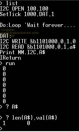
OK, trying to write your suggested routine, for the purposes of experimentation and learning. This is what I have: 
How come A$, which should be the value of whatever seconds is, is always zero? Should it not be incrementing each time I read it? Smoke makes things work. When the smoke gets out, it stops! |
||||
| BobD Guru Joined: 07/12/2011 Location: AustraliaPosts: 935 |
Grogster, val(A$) is 0 because there is not a valid numeric in that variable. You have to format the data from the clock. The data in the time registers is two 4 bit numbers which each have to be converted to decimal and added together. I will post some code when I can find it but I think one of the Johns posted some a couple of days back which will have the details. Bob |
||||
| BobD Guru Joined: 07/12/2011 Location: AustraliaPosts: 935 |
I have found some code to interpret the RTC time and date data. This does not apply to all data in the DS3231. Read the datasheet. Seconds = (RTCdata(0) and &h70)\16*10 + (RTCdata(0) and &h0f)
Minutes = (RTCdata(1) and &h70)\16*10 + (RTCdata(1) and &h0f) Hours = (RTCdata(2) and &h70)\16*10 + (RTCdata(2) and &h0f) DoW = RTCdata(3) and &h07 Date = (RTCdata(4) and &h30)\16*10 + (RTCdata(4) and &h0f) Month = (RTCdata(5) and &h10)\16*10 + (RTCdata(5) and &h0f) Year = (RTCdata(6) and &hf0)\16*10 + (RTCdata(6) and &h0f) |
||||
jman Guru Joined: 12/06/2011 Location: New ZealandPosts: 711 |
I2C write I2caddr, 0, 1, 0 I2C Read i2caddr, 0, 8, RTCbuff(0) This will set the address to start reading at 0 then read the contents of 0 thru 7 to RTCbuff(0) Regards Jman |
||||
Grogster Admin Group Joined: 31/12/2012 Location: New ZealandPosts: 9308 |
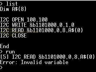
OK, tried a little more on this - reading into an array is rejected. 
I suspect that this is perhaps because there was mention that the RTC code supplied in the zip was meant for a MM, not a uM, so that might explain why it does not want to behave as expected. EDIT: I might have a play with the EEPROM chip now - getting frustrated with the RTC. 
This is not to say I am ready to give up on it - far from it - just want to try the other chip on the same module. Smoke makes things work. When the smoke gets out, it stops! |
||||
| JohnS Guru Joined: 18/11/2011 Location: United KingdomPosts: 3816 |
Try ASC(A$) or if A$ is an array then ASC(A$(index)) where index is the element number you want. By way of example, suppose A$ was a space. VAL(A$) would be 0. ASC(A$) would be 32 (because the ASCII value of a space is 32). John |
||||
| Page 1 of 3 |
|||||