
|

|
Forum Index : Microcontroller and PC projects : MicroMite 44 Pin TQFP Eval PCB/Module
| Page 1 of 11 |
|||||
| Author | Message | ||||
| WhiteWizzard Guru Joined: 05/04/2013 Location: United KingdomPosts: 2817 |
New Post started (from Beta Testers) . . . paceman I use 0.8mm board and a HBC220 modified laminator - no problems so far! Grogster A smart little trick to create a very accurate double sided PCB is to use two 0.8mm single sided copper clad boards etched separately. I place a wire pad on each corner (outside the required area) as a guide for alignment. Once both boards etched, drill through the four wire-pads as accurately as possible on the first board, then repeat for the second board. Then simply line the two PCBs back to back using a component lead off-cut to line up the boards. End result is a 1.6mm PCB with near perfect alignment. Hope this helps . . . For everything Micromite visit micromite.org Direct Email: whitewizzard@micromite.o |
||||
| WhiteWizzard Guru Joined: 05/04/2013 Location: United KingdomPosts: 2817 |
Update: Below are the two boards making up the double sided PCB. 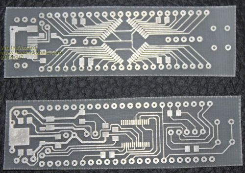
Ignore the rough cut - I will file this down, and round the corners, once boards attached to each other. Only one short detected on FTDI chip (bottom board). Will update picture once boards attached For everything Micromite visit micromite.org Direct Email: whitewizzard@micromite.o |
||||
| robert.rozee Guru Joined: 31/12/2012 Location: New ZealandPosts: 2350 |
i'm going to suggest the current path is too complicated for many. making it just a single-sided board opens it up for easier home fabrication and assembly using simpler tools and weaker eyes. and cheaper. my ideal would be a square board, 2"x3". no need for onboard serial to usb bridge, as these can be had for just 2 or 3 dollars from ebay, delivered. as i've said before, the CP2102 makes an excellent solution, and if MMbasic can't handle that then MMbasic needs adjusting. when a usb to serial bridge is so cheap from ebay, it makes little sense to place it onboard. onboard optional 3-terminal LDO 3v3 regulator, TO220 package. 6-pin header for ICSP and 6-pin header for ttl serial. pinouts of serial to match FTDI cable configuration. jumpers/links to allow for power to come from serial connector, 2xAA batteries, or via regulator. all other port pins just bring out to lands around the edge. if convenient, perhaps group together as deemed appropriate (ie, all analog together, I2C, SPI, etc). all components (except processor) to be through hole. a 3mm hole in each corner of the PCB to allow fitting some small feet for when sitting on the workbench (the processor will be on the underside). just my 2 cents worth, rob :-) |
||||
| paceman Guru Joined: 07/10/2011 Location: AustraliaPosts: 1329 |
I'll have to try some 0.8mm board - it might be OK on the Lowell. Only snag will be that I'll waste the 1.6 boards I already have! Greg |
||||
| Lou Senior Member Joined: 01/02/2014 Location: United StatesPosts: 229 |
WhiteWizzard, I like the board you have done with the 40-pin DIP footprint although Robert's suggestion makes sense. If you make either board for sale, blank, populated, or any combination I would be interested in at least a few depending on the price. If not, maybe we can make them here, they would be nice toys to play with. In the meantime, I just received my 32MX 44-pin chips from MicroChip this morning. The break-out boards I ordered from SparkFun are stuck in transit in Kansas due to heavy snow and adverse weather. That will delay my efforts to beta test until at least Monday. https://www.sparkfun.com/products/8879
Sorry, new to TBS I don't know how to make a link yet but above is the board coming. Lou Microcontrollers - the other white meat |
||||
Grogster Admin Group Joined: 31/12/2012 Location: New ZealandPosts: 9309 |
Here it is then: Sparkfun Link They are dead easy - click the button above the editing window - picture of globe with chain-link. Type in what you want on the screen, and press ENTER or click OK. Paste your web link, and press ENTER or click OK.  Smoke makes things work. When the smoke gets out, it stops! |
||||
Grogster Admin Group Joined: 31/12/2012 Location: New ZealandPosts: 9309 |
That is actually very crafty. 
I don't have any 0.8mm PCB stock, but it is easy enough to get - perhaps I will try that one day. Still, I prefer a PCB house for prototyping these days - even single-sided has started to move to them, then I don't have to stuff around etching things at the weekend.  Costs money, that's true, but can well be worth it for prototypes - you know it will be perfect, and you don't have to lift a finger. The only downside is time(not counting the money mentioned above), as home etching can be done in one day, and you can be assembling your board the same day you etched it. For me, that USED to be something I would do, but with other things always cropping up, a couple of days for the PCB house to produce the prototype is no hassle for me. Costs money, that's true, but can well be worth it for prototypes - you know it will be perfect, and you don't have to lift a finger. The only downside is time(not counting the money mentioned above), as home etching can be done in one day, and you can be assembling your board the same day you etched it. For me, that USED to be something I would do, but with other things always cropping up, a couple of days for the PCB house to produce the prototype is no hassle for me.  Smoke makes things work. When the smoke gets out, it stops! |
||||
| WhiteWizzard Guru Joined: 05/04/2013 Location: United KingdomPosts: 2817 |
Hi, Thanks for everyones feedback. In response to Rob and Lou, my original idea was for a very simple single sided PCB comprising with just the TQFP and caps - creating basically a 44 Pin DIP to plug into a breadboard (see below). 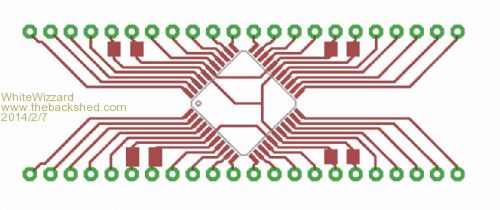
This basically becomes as easy to use as the 28 Pin PICs but with all the extra pins of the TQFP package. If anyone is interested, I will gladly provide the Gerber files for this PCB for people to make at home. Regards, Phil For everything Micromite visit micromite.org Direct Email: whitewizzard@micromite.o |
||||
| MOBI Guru Joined: 02/12/2012 Location: AustraliaPosts: 819 |
Will this plug into a bread board and still leave room for jumper leads either side? David M. |
||||
| WhiteWizzard Guru Joined: 05/04/2013 Location: United KingdomPosts: 2817 |
Will this plug into a bread board and still leave room for jumper leads either side? Hi MOBI, Yes. 0.7" between the two rows of pins making it breadboard friendly. This leaves room for 3 jumper leads either side on a standard breadboard. For everything Micromite visit micromite.org Direct Email: whitewizzard@micromite.o |
||||
Grogster Admin Group Joined: 31/12/2012 Location: New ZealandPosts: 9309 |
I'd be very interested in the Gerber for this. What size SMD caps are you using? 1206's? Apart from the 47uF cap on pins 6 and 7, the others are 100n PSU filter caps I guess? Smoke makes things work. When the smoke gets out, it stops! |
||||
| WhiteWizzard Guru Joined: 05/04/2013 Location: United KingdomPosts: 2817 |
1206's? All that is required is a usb-to-uart module and a ICSP (+10K on MCLR). However beware of any max current limitations from the usb-uart module as some are very low. Its fine if you're not driving many outputs but as soon as a few LEDs are used,for example, then I strongly would recommend a dedicated 3v3 LDO to prevent unusual behaviour. My preference is MCP170x (available in breadboard friendly packaging). Another trick I use when more than 200mA is required I tend to use multiple MCP170x's (rather than stressing them to their 250mA limit). For everything Micromite visit micromite.org Direct Email: whitewizzard@micromite.o |
||||
Grogster Admin Group Joined: 31/12/2012 Location: New ZealandPosts: 9309 |
Thanks a bunch for your reply. 
My preference is also for the MCP1703 series regulators, and I have plenty of both the 5v and 3v3 ones(in SOT-223). 
I only asked about the 1206 SMD, as I have plenty of these in stock - they are my preferred SMD size, as they are not hard to hand-solder. I have 1uF ceramics in 1206, but no 47uF's. I will get some from Element 14 next week. I also have a breadboard with a plug-in regulator module which supplies regulated 12v, 9v, 5v and 3v3. Smoke makes things work. When the smoke gets out, it stops! |
||||
| WhiteWizzard Guru Joined: 05/04/2013 Location: United KingdomPosts: 2817 |
Hi Grogster, As a reference for the 47uF cap, I use the following product code from RS Components: 547-9984. If you search for TPSB476K006R0250 on Farnell's site you will find it but unfortunately it is double the cost of RS. This cap is 3.5mm long and slightly wider than a 1206. This is why you will see a slightly bigger pad size on the Pin6/7 cap. Totally agree with you regarding 1206's, especially when the PCB has so many 0.1" pins it is pointless using 0805s! Another trick: solder the Caps on top of each other to give a higher value. 4x10uF ok but 47x1uF getting a bit too silly!!! 
Regards, Phil For everything Micromite visit micromite.org Direct Email: whitewizzard@micromite.o |
||||
| Geoffg Guru Joined: 06/06/2011 Location: AustraliaPosts: 3196 |
If you are using SMD components you could use a 10uF ceramic instead of 47uF tant. Geoff Geoff Graham - http://geoffg.net |
||||
| WhiteWizzard Guru Joined: 05/04/2013 Location: United KingdomPosts: 2817 |
Geoff Grogster, So if you're in a rush to get set up you could use ten 1uF's stacked on each other!! For everything Micromite visit micromite.org Direct Email: whitewizzard@micromite.o |
||||
| WhiteWizzard Guru Joined: 05/04/2013 Location: United KingdomPosts: 2817 |
Hi, Prototype now finished  . .
Loaded HEX file and everything worked first time (I really like this about all of Geoff's projects!) Top: 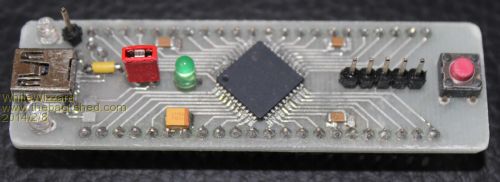
ALL 44 pins brought out to the two rows of header pins. Pin 1 bottom left, then anticlockwise to pin44 on top left (Identical to a DIP) Tx Led (top left) Mini USB (COMS and/or 5v power in) Rx Led (bottom left) Single Pin next to Tx Led = USB 5v output Red Jumper = Disconnects 5v USB power from circuit (i.e. on/off switch) Green LED = 3v3 Power (from onboard dedicated reg) 47uF tant below green Led ICSP 5-pins Reset Switch (keeps Tera Term connection open while reseting PIC only) Note the positions of the reset switch and ICSP mean that you cannot connect a PicKit3 the wrong way round (Come on - we've all done it at some time!  ) )
I've included 3x0.1uF decoupling caps to eliminate any issues (even though the 28 Pin PIC worked ok without them) Bottom: 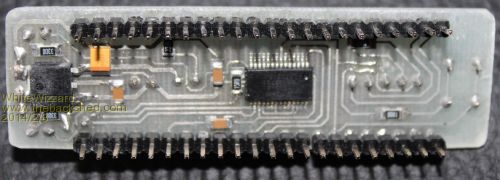
3v3 Dedicated 1A LDO (LF33) (left) FT232RL USB-to -UART (centre) For everything Micromite visit micromite.org Direct Email: whitewizzard@micromite.o |
||||
| WhiteWizzard Guru Joined: 05/04/2013 Location: United KingdomPosts: 2817 |
And here it is in operation. Doing the usual thing first - blinking an LED. 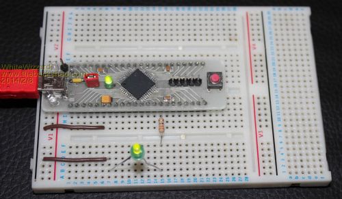
Note this is on Pin 15 - no issues Also to confirm that there are three available breadboard holes either side of the module (angle of photo clearly shows this on the bottom row) For everything Micromite visit micromite.org Direct Email: whitewizzard@micromite.o |
||||
| Lou Senior Member Joined: 01/02/2014 Location: United StatesPosts: 229 |
Nice board WhiteWizzard. I am interested in Gerbers for both single and double sided boards, perfect protoboards for the 44-pin chip. MicroChip specs a 10uF low series resistance (1ohm) for VCap. I have been using a 22uF tantalum for VCap and one .1uF on pins 27 and 28 on the uMite 28 boards without problems. For regulators I'm using 78L05 for 5v and MCP1702 for 3.3v, both are LDO. Thanks Grogster for the tutorial on links. Lou Microcontrollers - the other white meat |
||||
donmck Guru Joined: 09/06/2011 Location: AustraliaPosts: 1313 |
Prototype now finished  . .

Note the positions of the reset switch and ICSP mean that you cannot connect a PicKit3 the wrong way round (Come on - we've all done it at some time!  ) )
A fine job Phil. I find it very hard to fault as it seems to tick all the boxes. Just a couple of items. A single pin for +5V out? It would be good if you can squeeze a GND pin beside it, rather than the user chase the appropriate GND pin on the 44 pin DIP device, or elsewhere on the board. I assume it could be used for 5V in, or 5V out? A 5 pin PIC ICSP header? Cheers Don... https://www.dontronics.com |
||||
| Page 1 of 11 |
|||||