|

|
Forum Index : Windmills : PMAs for Beginners
| Page 1 of 2 |
|||||
| Author | Message | ||||
| mulligan Newbie Joined: 26/09/2011 Location: United StatesPosts: 10 |
I have recently endeavored into the fields of basic electricity and magnetism, and made attempts to construct a basic Permanent Magnet Alternator. I gather this is a veteran-esque forum, but I hope some of that experience could be easily applied to help a novice. I am teaching myself these subjects, with library books and experimentation. With such, I am having difficulty getting a PMA to generate even the smallest amounts of electricity. Here is what I have, Two recycled speaker diaphragms, each speaker has two stacks of 3/4" ceramic magnets, five magnets each stack. The speakers are set on an axel facing one another with approx. 1" between them, the opposite poles of the magnet columns aligned with the opposing rotors. One coil of 28 gauge enameled wire, approx 150-200 turns in the coil, set between the two rotors. I stripped the enamel from the two ends of the coil and soldered them to two lead wires. The axel is connected to a crank handle that spins the axel directly. The movement is smooth and balanced, capable of achieving aprox. 120 rpms by hand. With all this set-up, I connect the lead wires to a multi-meter and set it into motion, but not even a smidgeon of voltage registers. I will be satisfied with any beginning advice, particularly things that often escape or riddle beginners in the complexity of this science. Could my lead wires be soldered poorly, and cause a complete loss of voltage? Do I simply need more coils with more turns? Are the ceramic magnets not strong enough? I will attempt to upload some photos soon to assist in any digital trouble shooting. Thanks for any considerations! |
||||
| Greenbelt Guru Joined: 11/01/2009 Location: United StatesPosts: 566 |
mulligan Hi, It's difficult to picture what you have, this is what comes to mind for me so I know I must be missing something.? I have included a little help for Uploading pictures, Remember only JPEG or GIF picture format will upload to this site,, and Pictures should be cropped to the subject view, this will hold a better resolution when the web site re-sizes your pictures. Welcome to the forum, We will help in any way we can. ---------Cheers, Roe Time has proven that I am blind to the Obvious, some of the above may be True? |
||||
MacGyver Guru Joined: 12/05/2009 Location: United StatesPosts: 1329 |
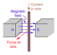
mulligan Welcome to the forum. I will run through some of the basics and with a few changes on your end, you will be able to manufacture some evidence of electricity. First off, a circuit must be completed to do anything. The wires as well as the magnetic fields must form a complete circuit. The magnetic "flux" travels from one pole to the other, but in order for there to be a complete circuit, the flux must return to its point of origin. This is a VERY important concept to understand before moving on. Imagine a horse-shoe magnet in the shape of a "U". If you touch either leg of the magnet at its open end with a piece of iron, you'll feel a slight attraction. Each pole has its own magnetic field. If, however, you place the iron such that it touches EACH pole simultaneously, the "magnetic circuit" is completed and the attraction is several times that of either of the two individual attractions. See how that works? The same principle must be maintained when building an alternator or generator. The magnit circuit must be completed. In your example using the speakers' magnets, I must change the subject slightly and explain something. A cylinder magnet can be magnetized on either its faces (axial magnetism) or about its circumference (diametrical magnetism). The speaker magnets MAY be magnetized on their rounded sides, accounting for an incomplete magnetic flux pathway and no electricity produced. Assuming your magnets are axially magnetized (across their faces with a N on one face and a S on the other), in order to complete the magnetic circuit pathway, you'd have to somehow join the two outboard surfaces to each other. Without doing this, the attraction between speaker magnets is minimal, but should still be enough to gain at least some "evidence" of electric charge. Let's hope you are using a volt meter instead of a light bulb to measure evidence of electricity! Let's take a look at your test coil. You said there were 150 to 200 turns of wire. That's tantamount to zero in this scenario, unless you were to have maybe a dozen magnet pair AND they were spinning by the coil at 120 rpm. In order for you to measure any usable current, that coil must go through the magnetic field at about 1200 times a minute! You can cheat this a little by attaching each of two leads from a volt meter to the two electric connections on a permanent-magnet type DC (direct current) motor and spin the motor shaft with your fingers. The mechanics of what I'm explaining here are all worked out already and you should "see" evidence of electricity production at the meter. Lets talk about the coil as it is presented to the magnetic flux. When a wire passes through a N-S field, a current is induced in one direction. Reversing the direction of motion OR reversing the wire direction induces a current in the opposite direction. I said all that to say this: You must make sure one side of the coil passes through the field while the other side of the coil does not or at best, passes through an oppositely-oriented flux field. Fool around with this on paper. Draw a large coil and visualize the "legs" of the same coil passing through a magnetic flux field, then draw an arrow in the direction of current flow (completely arbitrary for this discussion). You'll readily see that if the opposite "leg" of the same coil passes through the same-direction magnetic flux path way, the current in each "leg" of your coil generates the same current in the wire but each current-flow direction is OPPOSITE and since it's the same wire, this cancells the current. This is called "cancellation" and can be a huge problem when designing coils to fit into a magnetic array. Here's a little picture to facilitate what I'm talking about so you'll better understand what I'm saying: 
Study this little picture just to get the idea of how a current is "induced" into a moving wire. The wire can move or the magnets can move; doesn't matter. There just needs to be movement. "Force on Wire" means "direction wire is moving through flux pathway." Here's another picture of a similar situation, but not as simplistic: 
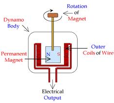
In this examplle, the magnet is "diametrically" magnetized. Study this some and try to modify what you've constructed. Be sure to use a volt METER to measure your electricity production. It won't be much. A meter is absolutely necessary to view it. There's a lot more to this (alternating current, direct current, etc.) but for now, just get this much under your belt, then start asking more questions and the folks here will chime in to lead you down the pathway. . . . . . . Mac Nothing difficult is ever easy! Perhaps better stated in the words of Morgan Freeman, "Where there is no struggle, there is no progress!" Copeville, Texas |
||||
| Gizmo Admin Group Joined: 05/06/2004 Location: AustraliaPosts: 5078 |
Good post Mac Hi Mulligan Yeah we would need some pictures or diagrams to really see whats going on. But one thing to check, the coil inside diameter is bigger than the magnets outside diameter. For example, if the diamter of the magnet stack is, say, 50mm, then the coil needs to wound on a 50mm former, so its finished inside diameter is 50mm or bigger. Any loops of copper wire that are smaller will be cancelled out, to some degree. Also, the obvious but often overlooked, is your multimeter set to read AC volts, not DC volts. Glenn The best time to plant a tree was twenty years ago, the second best time is right now. JAQ |
||||
| mulligan Newbie Joined: 26/09/2011 Location: United StatesPosts: 10 |
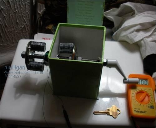
Good looks, fellow backshed members. Your timely and detailed responses are encouraging, especially in my frustration. Here are a few pictures of how it stands now, The magnet-stacks on the outside speaker are both south side faced out, the magnet-stacks on the inside are north side faced out. Is this the way to do it? Or have each speaker with a N and S magnet facing out and align the two speakers accordingly? I will make a coil with at least 500 turns and make the inside diameter of the coil bigger. With so few magnets, will it help to have more than one coil? If so, do they need less turns? And when I connect more than one coil, do I just connect them in parallel? Cheers, Caden |
||||
| mulligan Newbie Joined: 26/09/2011 Location: United StatesPosts: 10 |
Here is a link...https://picasaweb.google.com/117472688880934885806/Se ptember26201102 |
||||
| mulligan Newbie Joined: 26/09/2011 Location: United StatesPosts: 10 |
Uhhh. one more time https://picasaweb.google.com/117472688880934885806/September 26201102 |
||||
| Gizmo Admin Group Joined: 05/06/2004 Location: AustraliaPosts: 5078 |
Try the link and image buttons  
The forum has tricks to break links unless entered correctly. It reduces spam. Glenn The best time to plant a tree was twenty years ago, the second best time is right now. JAQ |
||||
niall1 Senior Member Joined: 20/11/2008 Location: IrelandPosts: 331 |
the pics are almost working Mulligan..  ...your close ...your close
that,d be a big help to see how you lined up (and how many) mags you recycled from the speakers ...the coil tests might come a bit later good to see recycled stuff being tried ....power speakers can contain hefty ceramics niall |
||||
MacGyver Guru Joined: 12/05/2009 Location: United StatesPosts: 1329 |
Mulligan I couldn't make your link work. It might be me though; I'm a little slow these days. Anyways, at the bottom of the "Post Reply" box at the bottom of each page here. It's what I'm writing your reply inside of right now. At the top of the box, there's a picture of a tree with a blue arrow pointing up. If you click on that box, it brngs up another with a "Choose File" option. I like to drag my pictures to the desktop before I do a reply. That way they're all in one spot. Anyhow, just take it where it has to go and click on it, then hit "Ok". It takes from a few to several seconds for the system to upload your photos, but then they're there for all to see. Another way, as you've attempted, is to leave a link. To do that, click on the blue "Forum Codes" button and then click on this: URL=http://www.myWeb.com]My Link[/URL I've purposely left off the beginning and ending brackets, so the code will print and not create a blue hot link that leads nowhere. To use this, they'll each have to be left on. All you do is replace the source code by highlighting it with an apple-x (for Macs) and then highlight the link's source code and replace it. Where it says "My Link" just replace that with a word or two that identifies what you're doing like, Picture or Link or whatever. That way, folks can just click your link and see whatever it was you put up for show 'n tell. It's easy. If I can do it . . . believe me; it's easy. I can run an engine lathe with one hand, but when it comes to computers, I'm all thumbs. . . . . . Mac Nothing difficult is ever easy! Perhaps better stated in the words of Morgan Freeman, "Where there is no struggle, there is no progress!" Copeville, Texas |
||||
| mulligan Newbie Joined: 26/09/2011 Location: United StatesPosts: 10 |


|
||||
| Gizmo Admin Group Joined: 05/06/2004 Location: AustraliaPosts: 5078 |
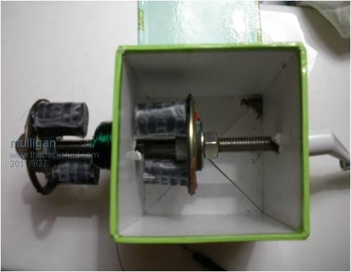
OK, looking at the photo, is the coil around the threaded bar, or out to one side? If its around the threaded bar, then the wires are in direction of rotation, so the magnets are passing along the wire, not across them. As Mac pointed out above, the magnet needs to pass over the wires at 90 deg to the wire. Glenn The best time to plant a tree was twenty years ago, the second best time is right now. JAQ |
||||
niall1 Senior Member Joined: 20/11/2008 Location: IrelandPosts: 331 |
nice machine !...pics are working fine mini axial alt then .. maybe a square bigger coil that has it legs directly between magnets would work better (or) wind a mini coil that fits directly two poles ... as you look at the pic each mag pole should be N.....S S.....N mini axial alt then .. niall |
||||
| mulligan Newbie Joined: 26/09/2011 Location: United StatesPosts: 10 |
The coil is fixed to the outside of the cardboard box and DOESN'T rotate when the threaded bar is rotated. I essentially used the box as the stator. |
||||
| Tinker Guru Joined: 07/11/2007 Location: AustraliaPosts: 1904 |
Mulligan, if those are speaker magnets then I suspect their magnetism is directed toward each other (across the threaded rod) and not at all towards the coil as you mounted it. IOW, it won't work the way you rigged it  . .
Try to relocate the coil so that it is inside just one rotating pair of magnets - leave the other pair off - to prove me wrong or right. It must be inside so that the whole coil is parallel to the rotating magnets and not with the rod through the coil center. Not really easy to do I should think, can you instead take the magnets off the backing plate individually and experiment then? First I would find out which sides of each individual magnet strongly attract each other and mark them with paint. Then I would mount the magnets on an iron backing so that the non marked sides stick to the iron and the marked sides face each other (the iron might be the inside of a piece of pipe if my guess is right). If you then locate your coil inside the faces of the marked magnet sides - so that the magnetic lines between the magnets pass through the coil center - you should generate AC voltage when the magnets are rotated, Have fun  Klaus |
||||
| scoraigwind Newbie Joined: 23/09/2009 Location: United KingdomPosts: 21 |

The magnetic flux has to pass thorough the coil in one direction and then the other, and this change has to take place rapidly. It's like links of a chain except that the links pass through each other to produce voltage. The above if it works is a picture of a simplistic configuration. Most are more complicated but they are designed to achieve the same thing. Hugh Piggott |
||||
| mulligan Newbie Joined: 26/09/2011 Location: United StatesPosts: 10 |
If I remove one of the rotors from the design I posted in photo and put the coil between the two stacks of magnets, and rotate the magnets while the coil is still, will that be enough force to push out a current? Also, does anyone have their own design or configuration for a mini PMA like I'm trying that can be constructed with the limited resources of round ceramic magnets, magnetic wire and an axel with a crank? I'd just like to find a design that works and then improve from there... Thanks, PS I'm ditching the speakers because they have a ring magnet around the base of them that I fear is interfering with my intended magnetic field. |
||||
niall1 Senior Member Joined: 20/11/2008 Location: IrelandPosts: 331 |
heres another design mulligan..... mini radial its radial in layout but uses one coil so is similar in that way to your original idea ....its an interesting alt i think theres also mini axials on utube ...worth a look niall |
||||
| Greenbelt Guru Joined: 11/01/2009 Location: United StatesPosts: 566 |
mulligan ---------Cheers Roe Time has proven that I am blind to the Obvious, some of the above may be True? |
||||
| mulligan Newbie Joined: 26/09/2011 Location: United StatesPosts: 10 |
Greenbelt Very nice rendering of my contraption. I had my magnets aligned as such, although the coil was placed differently; I had made the coil the identical size of the rotors diameter, so the magnets were spinning along the circumference of the coil throughout their rotation. Could this alignment have caused the "cancellation" effect I was previously warned of? With the coil set off to one side like you rendered, should the magnets pass through the center of the coil or along the outside "legs" of the coil? PS Please correct any terminology I misuse |
||||
| Page 1 of 2 |
|||||