|

|
Forum Index : Microcontroller and PC projects : Adapter PCB Idea
| Page 1 of 2 |
|||||
| Author | Message | ||||
jman Guru Joined: 12/06/2011 Location: New ZealandPosts: 711 |
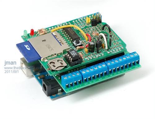
Hi all I was wondering if any of the PCB gurus out there could come up with a PCB for inputs outputs etc that plugs into a Maximite see the Pic. This PCB is the same size and shape as the current Maximite PCB with a 26 IDC connector mounted on the bottom in a DIL header if needed to make the height. Then fit a vertical mount 26 pin IDC on the Maximite so two boards can be plugged togther if the user prefers they can use 2 right angle connectors and a ribbon cable. On the PCB four or so analog inputs set up with resistors for voltage dividers and some bat diodes for protection. ie 2 resistors and 2 diodes per analog input maybe a 3.3 zener just in case (optional). 2 or so pins setup with 1 resistor to +5v for LM35Z temperature sensor use and 2 or 4 depends on space SPDT relays all this comes to the front edge and connected via PCB monuted screw terminals I am sure we can squeese an RTC in there to This way we just pick the resitor values and we are ready to measure analog ! I have add a pic a shield with screw terminals 
Regards John |
||||
| vasi Guru Joined: 23/03/2007 Location: RomaniaPosts: 1697 |
Hi John, An educational board (extension, shield, whatever) with all sorts of peripherals, switches and sensors can be easily designed but, an add-on board specific to your application is up to you (or at least, you can come up with all specifications and requirements). For an educational board, must be made a list or a sort of poll, to gather all the wishes... we may end up with two or three boards, depends on the application target... Vasi Hobbit name: Togo Toadfoot of Frogmorton Elvish name: Mablung Miriel Beyound Arduino Lang |
||||
VK6MRG Guru Joined: 08/06/2011 Location: AustraliaPosts: 347 |
Hi Guys, This is a an expander that I have drawn up to have made for my farm gate opener project. 6 digital inputs, 4 digital outputs, 2 relay and 2 transistor switched. Designed to plug onto the Maximite EV (MINI) PS. still a work in progress. 
Its easier to ask forgiveness than to seek permission! ............VK6MRG.............VK3MGR............ |
||||
jman Guru Joined: 12/06/2011 Location: New ZealandPosts: 711 |
So I got PCB's made for my requirements This plugs into the Maximite (Header on Maximite is a straight type) My PCB layout skills are not the best but the boards work ok. Specs Real time clock 4 relay outputs 4 Digital inputs (Transistor) 10 Analog inputs 2 of these are setup for LM35 temperature sensors. Analog has divider just pick resistors to suit your input voltage I have 2 spare boards with real time clock chips (8563) and crystals should anybody want one @ around $20 NZD (This is pretty much the cost price) Regards John |
||||
Xiongmao Regular Member Joined: 25/08/2011 Location: AustraliaPosts: 48 |
I'll take one. just PM me your details. |
||||
jman Guru Joined: 12/06/2011 Location: New ZealandPosts: 711 |
PM sent John |
||||
| Ray B Senior Member Joined: 16/02/2007 Location: AustraliaPosts: 219 |
VK6MRG & JMAN are you offering your artwork for those who want to "roll their own" or modify. e.g. maybe with DesignSparkPCB that was discussed yesterday or Eagle that will be promoted in the next Silicon Chip. RayB from Perth WA |
||||
jman Guru Joined: 12/06/2011 Location: New ZealandPosts: 711 |
Sure No Problem I did this one with Pad2Pad I will post the files here John Edit Files added 2011-09-10_222015_MaximiteAddon.zip |
||||
| Ray B Senior Member Joined: 16/02/2007 Location: AustraliaPosts: 219 |
Thanks John - downloaded file but wont open in DesignSpark or in DIPTrace where when I try to import as a PCAD ASACII PCB it fails to open. I downloaded your Pad2Pad & it opens there ok so file is not corrupt but then the SaveAs or Export choices are limited except maybe as DXF for the mechanical outline - which opened for me ok in TurboCAD. Hope these comments help others... So much for portability between applications. At the end of the day I know some members are producing boards for commercial purposes & yes they are well priced but then some others may want to make their own. Still battling with what PCB / Schematic program to standadize on as we all know once we start with one we don't want to convert. Cheers RayB from Perth WA |
||||
VK6MRG Guru Joined: 08/06/2011 Location: AustraliaPosts: 347 |
Maybe a good idea to have a poll to see what people are using to design PCB's. As Iím just starting to learn Design Spark, now would be a good time for everyone to come up with a common PCB design program for all to use. Its easier to ask forgiveness than to seek permission! ............VK6MRG.............VK3MGR............ |
||||
jman Guru Joined: 12/06/2011 Location: New ZealandPosts: 711 |
Yip I agree John |
||||
| vasi Guru Joined: 23/03/2007 Location: RomaniaPosts: 1697 |
1. I would say KiCAD for unlimited size and components and for a good PCB designer and good production files (it can be used in industrial environment). It can import (via some Eagle scripts) Eagle component libraries, boards and schematics. But you need to read a little .pdf tutorial (it come with the installer) to be ready to work with it. Not good for homemade CNC Router (maybe only for drilling)... It is available for Win&Linux (on Mac have some problems). 2. Eagle is the most used with good libraries and footprints for Arduino shields (also a lot of Arduino shields and other open hardware projects come in Eagle format) but is limited on board size. You can use free, excellent scripts to generate g-code. 3. DipTrace for the easiest CAD program but limited on PADS (300 pads, though the design can be continued using vias instead of pads) and not limited on board size. It also generate: [quote]DipTrace allows you to export edge polylines to DXF. The DXF files can be converted to G-code with Ace Converter (it's free).[/quote] So, very good for those having CNC Router and does not want to use other extra tools. Very good import/export features (imports Eagle schematics and components). Eagle complements it well. If a general PCB designer is wanted, then we must see what it have to offer on: - easy to use, - good component library, - component editor, - export/import features, - print features (for home made boards) - g-code features (home made CNC but not for all) - production files (for PCB fab houses). Vasi Hobbit name: Togo Toadfoot of Frogmorton Elvish name: Mablung Miriel Beyound Arduino Lang |
||||
| Ray B Senior Member Joined: 16/02/2007 Location: AustraliaPosts: 219 |
Once again Vasi can be relied upon to come up with alternatives like KiCAD. Following link compares KiCAD and Eagle http://www.bigmessowires.com/2010/05/03/eagle-vs-kicad/ RayB from Perth WA |
||||
bigmik Guru Joined: 20/06/2011 Location: AustraliaPosts: 2914 |
I use Protel Design explorer 99se,, Why??? Because its the one my Company wanted for their stuff and I know how to use it... Personally I find its interface quite awkward but it produces great results. Mick PS. There are some serious issues with Protel 99se and WIN 7, I have mine running in a VMware XPpro virtual Machine under WIN 7 home premium and its fine. Link here on how to set up VMWare (free) VMWare How-To Mik Mick's uMite Stuff can be found >>> HERE (Kindly hosted by Dontronics) <<< |
||||
| vasi Guru Joined: 23/03/2007 Location: RomaniaPosts: 1697 |
Nice comments on that article. I also can add that Eagle does not have a Pad editor on board as KiCAD have. By example, on your board you have 8 groups of drills with different diameters and your pCB fab house wants a maximum of 6 drill bits per board, with specific diameters. In Eagle, the only way to change the diameter hole of a pad is to modify the component inside the library tool. Is a pain. In KiCAD just double click on a pad and you have a dialog window with a lot of options and details. For KiCAD is already a complete Eagle component library ported. Just need to be downloaded and installed (from another site). I recommend reading the comments from that article to see where the author did mistakes in his evaluation. Nice article here but still, not the best one. Hobbit name: Togo Toadfoot of Frogmorton Elvish name: Mablung Miriel Beyound Arduino Lang |
||||
Bryan1 Guru Joined: 22/02/2006 Location: AustraliaPosts: 1344 |
I have tried using Eagle and Kicad in the past but I still prefer sprint layout to any other PCB software package. One doesn't need to have the part on file and it it is too easy to make new components and save them as a macros. The test feature is very handy for checking the circuits and any newbie trying for the first time will find it a easy package to learn. The best part it is a 10th or more less than any other pcb commercial package so home DIYer's can use it. The export feature is also great for guys that want to route the boards on a cnc and with one button click the pcb design can be set to isolation which is purfect for cnc milling. For testing I have exported a few pcb designs and simmed them in Kcam with success everytime. Cheers Bryan |
||||
Dinosaur Guru Joined: 12/08/2011 Location: AustraliaPosts: 311 |
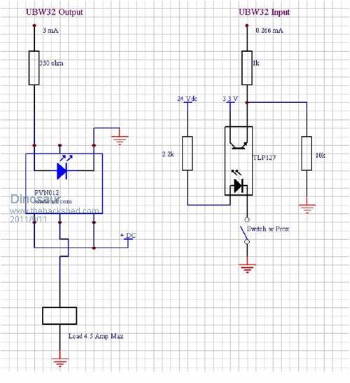
Hi All I am interested in buying interface cards for the Maximite or the DuinoMite. But I cant handle transistor inputs or outputs. They have to be opto's. Neither do I want to spend the time designing and getting them made. So, anyone who is contemplating such a design, I am interested. Regards Regards Hervey Bay Qld. |
||||
VK6MRG Guru Joined: 08/06/2011 Location: AustraliaPosts: 347 |
Can you make up a schematic of a single channel opto isolated input circuit and Iíll see if I can add it into my Maximite interface PCB design. Its easier to ask forgiveness than to seek permission! ............VK6MRG.............VK3MGR............ |
||||
Dinosaur Guru Joined: 12/08/2011 Location: AustraliaPosts: 311 |
Hi All Below a pic of what I use for the UBW32. 
There are better options for the Output opto which is a bit slow on the PVN-012 But I have this working reliably on Machines in Geraldton & Mildura. Regards Regards Hervey Bay Qld. |
||||
| Ray B Senior Member Joined: 16/02/2007 Location: AustraliaPosts: 219 |
My concept for a flexible I/O board is to have all of the MM I/O coming out on the board to headers with a range of headers to cross connect to on-board circuit module components like Optos, Relays etc. You just then cross connect what you require. If course some I/O would be dedicated to some purposed e.g. COM1 & would connect to TTL I/O header and also Max232. I'm a bit neurotic about blowing of the micro chip with strange voltages - hate to try to desolder & resolder it.  RayB from Perth WA |
||||
| Page 1 of 2 |
|||||