|

|
Forum Index : Microcontroller and PC projects : Internal RTC
| Page 1 of 4 |
|||||
| Author | Message | ||||
jman Guru Joined: 12/06/2011 Location: New ZealandPosts: 711 |
Hi All As per the other RTC thread I have managed to get my RTC inside the orginal case. This really cool as now when I power up the time and date is always correct. This requires Gerard's I2C firmware I have included the circuit diagram for reference (straight from the datasheet) 2011-07-19_174444_RTC.zip Regards John |
||||
| thetinkerer Regular Member Joined: 16/06/2011 Location: AustraliaPosts: 68 |
Cool! Well done John. |
||||
| Gizmo Admin Group Joined: 05/06/2004 Location: AustraliaPosts: 5078 |
Yeah I agree, nice work. I think the Maximite II should come in a bigger case. Its a bit of a squeeze in there. Glenn The best time to plant a tree was twenty years ago, the second best time is right now. JAQ |
||||
stuarts Senior Member Joined: 15/06/2011 Location: AustraliaPosts: 199 |
Thinking of putting mine into a bigger case with the Maximite mounted to the front of the case so that you have access to the leds, sdcard and switch. Extend the rear connectors to the back panel and have room to mount i/o boards behind the Maximite inside the case. Stuart Time is nature's way of keeping everything from happening all at once. |
||||
donmck Guru Joined: 09/06/2011 Location: AustraliaPosts: 1313 |
Incidentally, the Maximite SM1 is designed to fit a larger case. http://www.dontronics-shop.com/maximite-sm1.html This product has been designed to fit the Jaycar Case: HB5970 http://www.jaycar.com.au/productView.asp?ID=HB5970&keywords= HB5970&form=KEYWORD 
Cheers Don... https://www.dontronics.com |
||||
brucepython Regular Member Joined: 19/06/2011 Location: AustraliaPosts: 64 |
Thanks for this contribution John. Having reached the point of being annoyed by having to enter the date and time via my autorun.bas file I'm delighted you have made this available. However, sometimes I'm fairly thick (and extremely thick for the rest of it) and need advice about where the circuit diagram is. The ZIP file contains two sets of code, but no schematic. Bruce |
||||
jman Guru Joined: 12/06/2011 Location: New ZealandPosts: 711 |
Sorry I forgot to add it the zip file I have attached the datasheet circuit is in there R1 is optional. I used 2k2 resistors for the pullups tied to +5v John John2011-07-20_145333_DS1307.pdf |
||||
brucepython Regular Member Joined: 19/06/2011 Location: AustraliaPosts: 64 |
Thanks John. Now all I need is a chance to go shopping. |
||||
VK6MRG Guru Joined: 08/06/2011 Location: AustraliaPosts: 347 |
Hi guys, I thought I'd add my two cents worth about a RTC option. http://cgi.ebay.com.au/ws/eBayISAPI.dll?ViewItem&item=270741 884749&ssPageName=STRK:MEWAX:IT

I found this on eBay, and should be a straight forward process to integrate into the Maximite. (I think  ) )
Matt Its easier to ask forgiveness than to seek permission! ............VK6MRG.............VK3MGR............ |
||||
jman Guru Joined: 12/06/2011 Location: New ZealandPosts: 711 |
Looks like the listing has been removed got a new link ? John |
||||
jman Guru Joined: 12/06/2011 Location: New ZealandPosts: 711 |
http://www.ebay.com.au/itm/PCF8563-RTC-Board-PCF8563-I2C-int erface-3-3V-battery-/250846999759?pt=LH_DefaultDomain_0&hash =item3a67a574cf That links works Looks very good for small price John |
||||
jman Guru Joined: 12/06/2011 Location: New ZealandPosts: 711 |
Hi Matt I have ordered one Once it arrives and I have it working I post the results. John |
||||
| Ray B Senior Member Joined: 16/02/2007 Location: AustraliaPosts: 219 |
also available for $7.90 is this excellent product - takes about 10 days from Thailand although it is an aussie web page http://www.futurlec.com.au/Mini_DS1307.jsp RayB from Perth WA |
||||
stuarts Senior Member Joined: 15/06/2011 Location: AustraliaPosts: 199 |
Ray, I ordered one about a week ago. Hoping it gets here soon. A bit hard to beat the price. Stuart Time is nature's way of keeping everything from happening all at once. |
||||
jman Guru Joined: 12/06/2011 Location: New ZealandPosts: 711 |
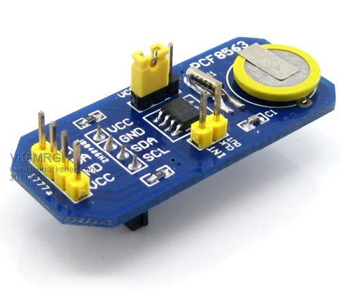
Hi I recieved my PCF8563 board yesterday Nice little board well made great price blah blah blah :) So i have it working now Attached is the code I used Remember to run the wr8563 after setting the correct date and time on the Maximite 2011-07-28_171338_PCF8563.zip John |
||||
| heppy36 Regular Member Joined: 29/07/2011 Location: AustraliaPosts: 54 |
Hi can you provide Pic on how to wire it in? Thanks Heppy |
||||
jman Guru Joined: 12/06/2011 Location: New ZealandPosts: 711 |
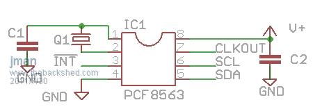
Hi This device is connected just like any other I2C device Pin 12 maps to MCU pin 43 (SDA1) and pin 6 on the I/O connector (revised schematic) or pin 21 (original schematic). Pin 13 maps to MCU pin 44 (SCL1) and pin 8 on the I/O connector (revised schematic) or pin 19 (original schematic). The PCF8563 has built in pullup resistors to the VCC line so no need for those You can get +5V from I/O connector pin 23 (revised schematic) or pin 3 (original schematic). A ground will also have to be run to the I2C device (I/O connector pins 1,2,25,26). This device will also run from 3.3V in that case pin 24 (revised schematic) or pin 4 (original schematic) Hope this helps Attached is a circuit diagram ofr the PCF8563 
|
||||
jman Guru Joined: 12/06/2011 Location: New ZealandPosts: 711 |
Hi I have removed the vero board version and installed the PCF8563 Ebay version inside the case Looks just like a bought one :) John |
||||
| heppy36 Regular Member Joined: 29/07/2011 Location: AustraliaPosts: 54 |
Thanks Heaps (Looks like it was made for it) Cheers Heppy |
||||
| seco61 Senior Member Joined: 15/06/2011 Location: AustraliaPosts: 205 |
Hi John. As regards the 5V and 3.3V connections, on the original schematic they were shown on the wrong pins - so 5V is on pin 4 and 3.3V is on pin 3. regards Gerard (vk3cg/vk3grs) Regards Gerard (vk3cg/vk3grs) |
||||
| Page 1 of 4 |
|||||