|

|
Forum Index : Windmills : time to add a generator
| Page 1 of 2 |
|||||
| Author | Message | ||||
| Air Bender Senior Member Joined: 25/01/2011 Location: AustraliaPosts: 206 |
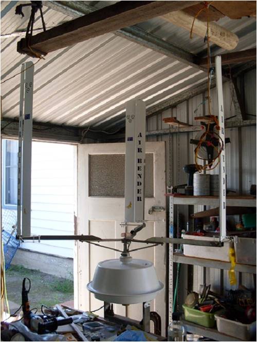
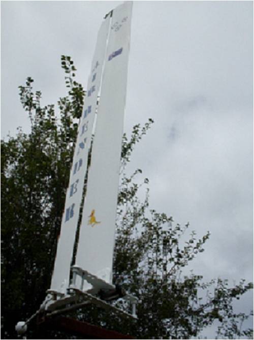
I have been experementing with vawt blades on a free spinning rotor in the back yard for the last 6 months, haveing followed the development of sailing boat wings over the years I went down this path. The last set of blades i built are called 2 element blades which clearly out performed the single element blades both on revs and low wind start up speed.if any one is unclear on multi element wings they can look up the latest on the americas cup,sorry i havnt added links as this is the first post i have ever entered into a forum. Multi element wings are used on F1 spoilers as they give the most down force for the least drag. So now its time to add a a load to the blades, thats how i discovered this site while looking for generators. I droped into my local washing machine repairer who i discovered is a reader of this site, so i scored a freeby F/P. A new rotor has been built and it is attached to the F/P which i have decogged, I have retifiers and am building an electrical box and a 5 meter piviting tower, when that is finnished I plan to put it up in the air with the sandard stator, keep a daily log on the DC volts it is puting out over a period of time for the wind conditions i have. Hopefully from this I will be able to work out which way to rewire the stator. I will take some pictures and try to post them if any one is interested but that might be be more complicated to me than rewiring the stator. |
||||
| isaiah Guru Joined: 25/12/2009 Location: United StatesPosts: 303 |
I posted pictures here so most any one should be able to post them. If you try and it doesn't work some one will help you out. It would be nice to see those blades. I use a breaker box out of a salvaged mobile home for the electrical. I hook it up backwards by putting the input from the mill on one of the breakers and use what was the 'incoming mains" as my out going to the battery bank (no grid tie here) this way you have a separate breaker for another mill or solar panels charge controllers or what ever else you may want to hook in. We will probably be going to a pic logger in the future after we get the anemometer project finished. see anemometer under other stuff Well welcome aboard. Isaiah URL=http://www.motherearthnews.com/Renewable-Energy/1973-11- 01/The-Plowboy-Interview.aspx>The Plowboy Interview[/URL> |
||||
| Gizmo Admin Group Joined: 05/06/2004 Location: AustraliaPosts: 5078 |
Hi Air Bender, welcome to the site How big is the VAWT, height and width. Just want to see if you have enough area to drive a F&P. VAWT's need to be a bit bigger than a HAWT to drive a F&P. Glenn The best time to plant a tree was twenty years ago, the second best time is right now. JAQ |
||||
| Air Bender Senior Member Joined: 25/01/2011 Location: AustraliaPosts: 206 |
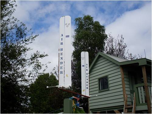
Blades are one meter high and diamiter of the rotor is 1.5 meters this is ajustable. The new mill will be running with 3 blades as the old test rig i have only runs two which gives a very pulsating rotation but it has been Quicker and cheaper building only two. Increasing blade size is not a problem as this is were my main interest lies. i am trying set it up so i can change blades easly and quickly. i have made headway in geting some pictures up i have managed to downsize the picsels but i ran out of time, had to go to work 12 hour night shift. |
||||
| KarlJ Guru Joined: 19/05/2008 Location: AustraliaPosts: 1178 |
must do at least some form of rewire or potentially lethal voltages obtainable at even low speeds also must have a load to connet to it, even if its just a length of fencing wire wrapped around a fluro tube. love some pics, admire your efforts most of us here find VAWT's romantic as they are nice to look at and the way a turbine should be but sadly, not many work. Luck favours the well prepared |
||||
| Gizmo Admin Group Joined: 05/06/2004 Location: AustraliaPosts: 5078 |
Hi Air Bender It's a bit small to drive a F&P effectively, you would need something closer to 2 meters high by 2 meters wide to get any real power from a F&P. But it will give you a chance to experiment. I did play around with a Lenz 2 vertical and F&P, was good for about 40 watts max, it was 1.2 high and 1.3 wide, so I would expect around the same from yours driving a F&P. You would have better output if you built a axial flux alternator to suit from scratch, maybe something to consider further down the track. The F&P will get you started and experimenting anyway. Like Karl says, watch out for those voltages, it can kill if you dont pay attention. Ed talks about matching a axial to his Lenz2 here http://www.windstuffnow.com/main/lenz2_turbine.htm, he got some good results becasue it was better matched than the F&P I was using was. Glenn The best time to plant a tree was twenty years ago, the second best time is right now. JAQ |
||||
| Air Bender Senior Member Joined: 25/01/2011 Location: AustraliaPosts: 206 |


thanks for advise and i have taken onboard the caution on high voltage from the standard stator espeshly as i have children who are closly observing the progect. i am thinking of wiring one phase and taking readings from this. am i correct in presuming that to calculate the 3 phase output from this I just multiply the output by three. And i will be also adding a padlock to the cabinet. Initualy i would be happy with producing 40 watts as providing 12Volt power to the kids cubby is the main objective and any thing left over can be shunted to the shed. but i would certinaly like to improve on this in the future aspecealy the way they are prodicting power prices to rise, we have just instelled a grid conect solar array so that should keep the bills down for a while. So i will be keeping a close eye on your altrnator build projects as when time permits i think i would be cumfortable in taking a build like this espeshaly if i could copy of you guys. |
||||
| RossW Guru Joined: 25/02/2006 Location: AustraliaPosts: 495 |
No, you are incorrect there. Depending on how you wire it, you'll get a modest increase in voltage (square root of 3) or about 1.7 times the single-phase voltage (that would be wired in star). The DC output will depend on how you rectify and filter, but would normally be 1.4 times higher (peak) than the AC fed to it.. |
||||
| Air Bender Senior Member Joined: 25/01/2011 Location: AustraliaPosts: 206 |
Thanks Ross, I am going threw a bit of a learning curve and am enjoying it. The information you guys are getting out to the general public is invalueable. so please feel free to pick my progect to peices as i go, i am a big boy i can take it. Especialy if it saves me time and money in the long run i will be very gratefull. I had a bit of luck today as i was meant to be fixing the car but when i opened up the box with the part in it. it was wrong so correct part was ordered and i was left with the rest of the day free so i got some mill time in, electricl pannel nearly finished, and scrounged the material for my pivit tower which know i plan to make 4 meters high, (i dont want to push wy luck to far with the naubours and the coancil). I have a 2 meter post concreated into the ground and i have two peices of angle iron 4 meters long which i am going weld spacers inbetween the same width as the post, i hope not to have to use any stays on this. A few steps closer. Thanks for the help Dean |
||||
| Tinker Guru Joined: 07/11/2007 Location: AustraliaPosts: 1904 |
OK Dean, here's what would worry me about your interesting project. The wings appear only supported at the bottom, what would the centrifugal force do to the tips should they rotate at high speed? If they flex evenly fine but should one flex more than the others then you get unbalance which can be very destructive. Its hard to see from the pictures how rigid your build is. There was an interesting thread here a while ago with calculations just how large centrifugal forces are on rotating wings. Klaus |
||||
AMACK Senior Member Joined: 31/05/2009 Location: AustraliaPosts: 184 |
The post you are talking about Tinker(Klaus) was one put up by Downwind(Pete) I think you are talking about. It was on HWAT, but the calcs will give him an idear of the levels that a mill or blade has on it. Amack *Note to self 1. Make it thick 2.Make it heavy. 3.Make it stronger than it should be. 4. Don't rush the first job as the second job will cost more and take mor |
||||
| Air Bender Senior Member Joined: 25/01/2011 Location: AustraliaPosts: 206 |
Thanks Tinker and AMACK the point you have brought is the one that i have thought about most from the start. To me it is highly desirable to keep the inside clear so the lee blade gets clear wind. Also hy approach to keeping centrifical force down is to keep every thing above the rotor light my blades only weigh arond 380 g with most of this weight at the bottom. During testing in a couple of strong winds i had a failure at the centre pivit point of the cross arm. I have beefed this up a bit in my three blade set up and also hope that the smoother rotarion of the three blades will help. I have not tryed to calculacte the centrifical force on the blade as to do this i would have to break down the break down the weight distribution from the top of the blade to the bottom, i am very much working with guestamation here. Thanks Dean |
||||
| smithy Regular Member Joined: 30/01/2011 Location: AustraliaPosts: 52 |
Hi Airbender As commented by others certainly a weak point is whats going to happen when you get over 100 rpm on that design. I have seen a similar design before where the counter weight ensures that you blades are always facing in the optimal direction wrt the on coming wind (Angle of Attack). Its an interesting design, although possibly a tricky one to master. for your info the following is a calculator to assist in working out the maximum possible power available to a VAWT. Power in the wind = 1/2 * D * A * W3 D = Density of air (Kg/m3), approx 1.2 at sea level. A = Area of turbine (in meters squared) W = Wind speed in m/s At IUPAC standard temperature and pressure (0 °C and 100 kPa), dry air has a density of 1.2754 kg/m3. At 20 °C and 101.325 kPa, dry air has a density of 1.2041 kg/m3. Smithy "The answer my friend is blowing in the wind, the answer is blowing in the wind" Bob Dylan |
||||
| Air Bender Senior Member Joined: 25/01/2011 Location: AustraliaPosts: 206 |
I have tossed around the idear of adding bracing into the rig, especialy as i look at other vawt designs. But then i think that every time i add a brace i add two extra stress pionts to worry about. But this may be inevitable down the track. The counter weight was added when the centrifical force started messing up my blade angles. i have built quite a bit of ajustment into this area and i hope to simplify it as i start to get it worked out. At some point you just have to say put it up in the air and see what happens. Dean |
||||
| smithy Regular Member Joined: 30/01/2011 Location: AustraliaPosts: 52 |
The one that it looks similar to is the Sharp VAWT, but the sharp one has the counterweight attached to a pendulum to ensure it has the correct Angle of attack. Attacked is the link of the PDF of Peter's work. http://www.windgen.org/Sharp_Cycloturbine.pdf "The answer my friend is blowing in the wind, the answer is blowing in the wind" Bob Dylan |
||||
| Air Bender Senior Member Joined: 25/01/2011 Location: AustraliaPosts: 206 |
Hi Smithy, i thought about using centrifical levers and cams and things but moved away from this. mainly becouse of the reliebility isues. i have tryed to keep the moving parts down to the bear minimum. As it starts to rotate the rear elemont locks in against a stop which holds the blade at right angles to the rotor arm and then the only moving part is the forward element which moves from side to side about one centimeter at the trailing edge. This opens a slot from one side to the outer. This is done by the wind pushing on it just the same way as a sail boat does. The problem is a sail boat does not spin around in tight circles, So at one point centifical force becomes greater than the wind strenth itself. The forward element tends to remain with the slot open on the out side of the rotation and tends to act more as a blake.So i needed to balence the forward element against this. So then came the counter balance the counter balance has no moving parts and is just part of the forward element. If i have to much trouble with this desighn i will tend to drift back towards a more traditional vawt design, as i beleive that we should not move far away from the tryed and tested ways of doing things which i strictyly adhear to at work. Hay but this is not work so i can let myself go i bit. all the best Dean |
||||
| Air Bender Senior Member Joined: 25/01/2011 Location: AustraliaPosts: 206 |
Hi all Thank you for your concerns on the weakness on the point where the blades attach to the rotor. I think the greed for performance took over my better judgment in building here. So I will definatly be adding some 45 deg bracing in before i put it up. I have also been tossing up a couple of other ideas. They are to add a hinge something along the lines you guys use on the tails of your HAWTs. And to have the hinge where the blade attaches to the rotor, so in strong winds the blade hinges outwards, but i am unsure about the efect this will have on the balance when one blade pivots out first. This would definetly have an efect on the horizontol balance but should not effect the vertical balance, i may be wrong here. My second idea is to have a hinge some where along the rotor arm and have half or more of the arm hinging down. this would have the heavyer weight of the arm moving inwards with the lighter weight of the blade tip moving out, hopfully keeping the balance My main concerns with both these ideas is that i am adding three more moving parts and they will move on every rotation of the mill in strong winds. The leeward blade has centrificl force pushing it out with the wind helping. While the windward blade has the wind pushing against the centrifical force, So it will hinge down as it rotates to leeward and come back up as it rotates to windward. And this movement may have in a slamming effect as the blade comes back up. The visual effect of this may be interesting, as it might look a bit like those crazy rides that spin around and go up and down at the show. Any comments on this would be welcome. All the best Dean |
||||
| Tinker Guru Joined: 07/11/2007 Location: AustraliaPosts: 1904 |
Hi Dean, Reading your post above I see a man with his mind in overdrive (just like myself sometimes  ), who starts a job as complicated as it can be and then simplifies it along the way (have experience here ), who starts a job as complicated as it can be and then simplifies it along the way (have experience here  ). ).
Anyway, if you are worried about overspeeding in strong winds a shaft braking mechanism of some sort would be much more sturdy than any blade manipulation contraption. Just my opinion of course. Klaus |
||||
| Air Bender Senior Member Joined: 25/01/2011 Location: AustraliaPosts: 206 |
Thanks Tinker having an overactive mind can be a blessing and a curse, some times I just need to look away for a while, clear my mind and the right solution pops up. |
||||
| smithy Regular Member Joined: 30/01/2011 Location: AustraliaPosts: 52 |
I have seen some people use springs attached to the hinged section such that they go flatter as they VAWT speeds up. Yes it is a compilcated design for a first up. But satisfying if you can do it. :-) "The answer my friend is blowing in the wind, the answer is blowing in the wind" Bob Dylan |
||||
| Page 1 of 2 |
|||||