
|

|
Forum Index : Windmills : Petes’s AXFX
| Page 1 of 2 |
|||||
| Author | Message | ||||
Downwind Guru Joined: 09/09/2009 Location: AustraliaPosts: 2333 |
Pete’s wooden mill I recently started to give some serious thought to how I would construct a AXFX mill. I don’t have a lathe and tend to find solutions around this limitation and try to not to need putting jobs out for machine work if I can avoid it. My plan was to build a enclosed 12 inch generator along the lines of Gordon and Phill plus many others have also built. As always a base design gets changed to suit what equipment we have to work with and the materials we can source at a reasonable price. I had a trailer stub axle to use but in planning this posed a problem with mounting to get every thing true in alignment. I then had a thought it would be so much easier to have the whole hub assembly made as a single module and just bolt it in. Hmmm! I had a theory that this has already been widely done, so armed with a kit of tools it was off to a local car wreckers that allows the public to remove the parts they want and just pay for the parts when you leave. After 1-2 hours of disassembling many wheel hub assemblies I finally found what I was looking for….a bolt in windmill part for $13.00 that was made for the job…perfect!! 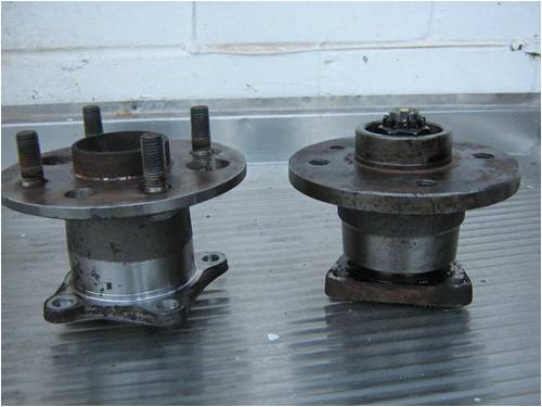
The one on the left is from a Toyota and the one on the right is from a Holden. They are the rear hub assemblies from a front wheel drive car. Many that I pulled apart have the rear brake drum as the bearing mount with the stub axle through it, no good for this application and far to much unneeded weight. I decide to use the Toyota hub as it has ball bearing races and the Holden hub has taper bearings. Also I figure Toyota is world wide and would be easier to find for most, but either would work well and both had their own advantages to design. 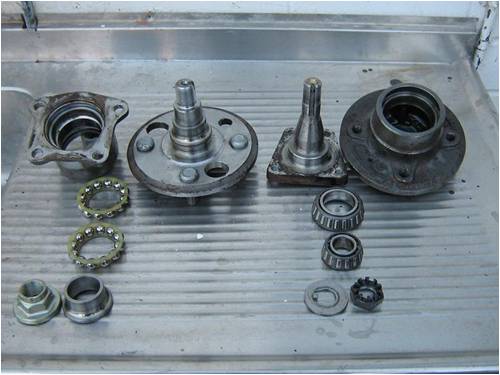
One of the big advantage with this sort of design is it allows for the whole generator to be unbolted from the tower (4 bolts) and no need to disassemble the head on the tower. This also allows for the complete generator to be changed over if desired while still retaining the same mounting stud Patten. Next was to work out how the stator could be mounted, and decided on a ring with the mounting bolts attached to it. I cut a ring out with the oxy torch, drilled and taped a thread in the holes, to take some 10mm (3/8) althread to allow for adjustment of clearances during the setup stage. 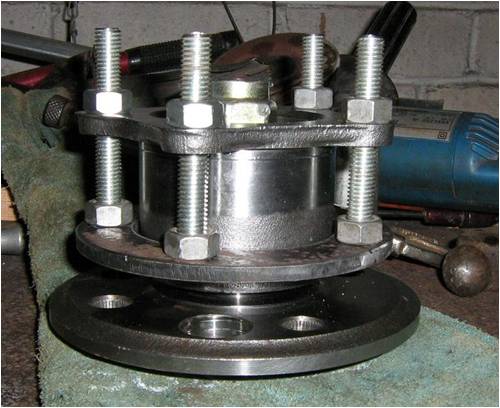
The next step was to workout how and where the magnet plates would locate and the stator size, so I could see what room I had to fit the coils into, and where the magnets would be located on the plates with what clearance everything had and needed. I had some sheets of Masonite and decided to cut some templates out and stack a few layers to get an approximate size for things. A circle cutter attachment on a hand held router made this a quick easy job. I then marked out the locations of the magnets and coils, placed the masonite discs in the cnc router and engraved the outlines for the coils and magnets. I am not that good a drawing in CAD on the computer, so this was my way of doing the physical lay up and it allows me to see exactly what fits where. Here is a magnet plate. 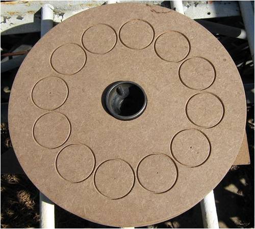
The Stator layout 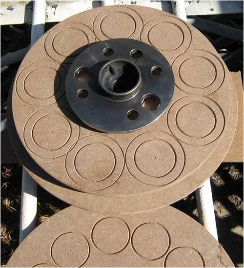
Ok I was out a little on some of my measurements and a couple of coils overlap slightly. It’s a very tight fit in space for the coils. All assembled here but not adjusted in the gap correctly yet. 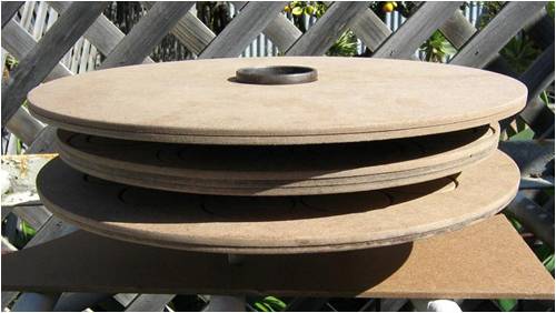
There will be a series of post spacers to join the two magnet discs together around the outside edge, hence the stator is slightly smaller to allow for these. Once the magnet plates are both secured together a sheet metal band will go around the complete outer circumference and attach to the post spacers that join the discs together enclosing the generator. The back magnet plate will have a centre disc cut out of it to allow for the generator to be disassembled from the rear by jacking off the back magnet plate. The centre disc will remain on the hub assembly to help enclose the generator. 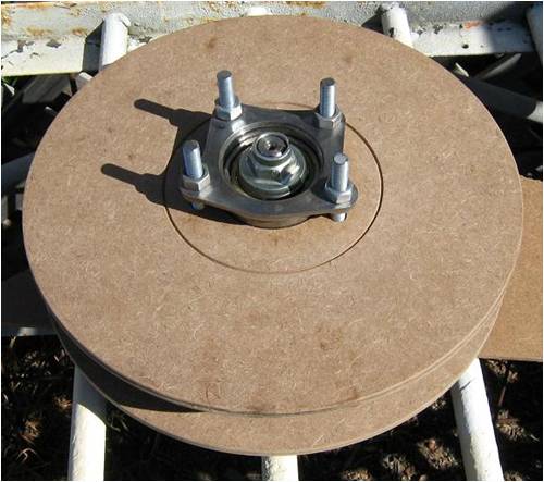
A plate and cap will cover the axle nut assembly and seal the bearings. The generator will mount from the 4 studs shown above. The blades will bolt directly to the 10mm front magnet plate and the front magnet plate will bolt to the hub where the car wheel would have normally. (bolts not shown yet) 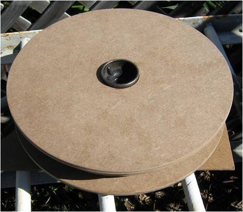
Ok well that’s the plan so far and in the near future will draw all the dimensions out and get the 2 plates laser cut. My intentions were to use the oxy torch to cut them out but on pricing 10mm plate, it worked out about $25.00 dearer to have them laser cut including the plate. I think the precise laser cut will be worth the extra few dollars. It will be several weeks before I advance further with this so stay tuned for a future update. Pete. Sometimes it just works |
||||
| VK4AYQ Guru Joined: 02/12/2009 Location: AustraliaPosts: 2539 |
Hi Pete Looks good mate I am waiting with bated breath for the next installment. All the best Bob Foolin Around |
||||
MacGyver Guru Joined: 12/05/2009 Location: United StatesPosts: 1329 |
Pete You do good-looking, careful work. I'm sure when it's a done deal, it'll be a showpiece. One thing I noticed, in the picture 4th from the bottom, the iron wheel looks as if it might wobble when it spins, due to there being holes on one side and not the other. Might want to take a look at that before you hoist it up the tower, eh? I'll be waiting with the rest of the crew to hand out the "ooos" and "aaaahs" when it's flying. . . . . . Mac Nothing difficult is ever easy! Perhaps better stated in the words of Morgan Freeman, "Where there is no struggle, there is no progress!" Copeville, Texas |
||||
niall1 Senior Member Joined: 20/11/2008 Location: IrelandPosts: 331 |
hi Pete the oxy cutting you used seems very interesting ....can i ask how hard is it to cut along a line and at the same time not get too blurred to whats going on ?....it seems a very usefull tool to have good luck with the build and i look foreward to your head scratchings about how things progress .. ps ...be carefull about hanging around in scrapyards , its addictive ..you might get a reputation as ...erm....Dumpster Pete..?  niall |
||||
Doug Regular Member Joined: 11/05/2010 Location: New ZealandPosts: 41 |
Hey Pete Talk about good timing. I have a Toyota hub exactly the same as yours and Ive been trying to decide the best way to do the same thing. I'll be following your build with great interest. Doug May The Power Be With You |
||||
Downwind Guru Joined: 09/09/2009 Location: AustraliaPosts: 2333 |
Hi Niall, Too late! Ive been addicted to scrap yards for years now, and scrap yard junk has born the essences of many a project around here. With scrap yards we often get a item 10 times better at a fraction of the price, than the alternative we would buy new. I was going to say why reinvent the wheel, but in this case we really are reinventing the wheel. 
I just love how a 14mm socket and 10 minutes in a wrecking yard and you have a ready made, bolt in windmill part, once you know what to look for. 
Pete. Sometimes it just works |
||||
Downwind Guru Joined: 09/09/2009 Location: AustraliaPosts: 2333 |
Hi Mac, No problem with balance as there is a matching hole opposite. Toyota make well engineered stuff and this hub has had 100,000 miles pre-test already done and it hasn't failed yet. Niall, You asked about Oxy cutting. I add a bolt on pin to the gas axe, that then makes it a circle cutter. I place a centre punch mark in the centre of the metal and the pin sits in the mark, then its just a matter of rotating the torch as you cut. Just as you would with a compass. No real need to follow the line and the eye sight dont get too blured either. Now cutting a straight line is not so easy, but circles are very easy. Pete. Sometimes it just works |
||||
| GWatPE Senior Member Joined: 01/09/2006 Location: AustraliaPosts: 2127 |
Hi Pete, straight lines are not that hard, if you have wheels on the cutting head. I just used to set up a guide along side the line, at the correct spacing to run the cutter along the line. A piece of angle held in place with a G-clamp, or vice grip worked OK. I presume you can still get the chalk stiks to mark with. Gordon. become more energy aware |
||||
Downwind Guru Joined: 09/09/2009 Location: AustraliaPosts: 2333 |
I have cutting wheels but think they are a bugger of a thing to use. The use of a staight edge for cutting along is a must for folks ilke me that get a little wobble and a shake up while cutting straight lines, circles are far easier me thinks. The chalk you refere to is actually raw talc, Its a rock they use to crush up and make talcing powder out of. You would of have had your bum powdered with it as a baby, but now days they use a different compound. The chalk/talc is still avaliable from welding supplies and the powder is still used for mixing with resin to make a putty for fiberglass repairs. Pete. Sometimes it just works |
||||
| Tinker Guru Joined: 07/11/2007 Location: AustraliaPosts: 1904 |
Pete, looking at your MDF layout plates I notice that your magnets are positioned awfully close together. Is there a reason for this? I always thought they should be at least one coil side width apart. Klaus |
||||
Downwind Guru Joined: 09/09/2009 Location: AustraliaPosts: 2333 |
Hi Klaus, Yes the magnets are close but that is one of the drawbacks with a 12 inch alternator. (also very tight on coil space) Sometimes we need to break the rules 
Its a trade off between a small loss in flux to a saving in weight. Being round magnets the loss between each magnet is not so bad as the actual magnet mass area is reasonably small where each magnet meets. It is not something i would proberly do with square magnets as the area would be much larger and higher losses. Then others go to pie shape magnets to get more magnet area side by side and then if we look at a F&P they are end to end, i feel if it was such a huge loss in flux then greater magnet spacings would have been used in these designs to. What i am doing here has all been done before with very good results. I am happy with not going for the big numbers and am looking for a good reliable mill that is quite and hassle free with 1-2KW output. My plan is to furl early and live to power another day. I feel to many get greedy with what the try to squeeze out at the top end and i think the lower half of a mills power curve is the important part. Pete. Sometimes it just works |
||||
| shawn Senior Member Joined: 30/03/2010 Location: New ZealandPosts: 210 |
Pete i always enjoy your work you are a true backyarder making new from old without sacraficing quality or performance  
Are you going to get out the chainsaw for blades? |
||||
Downwind Guru Joined: 09/09/2009 Location: AustraliaPosts: 2333 |
No, Paint brush and resin and glass for the blades. Im in the process of making the molds to have a go at casting a 1 piece hollow blade. I dont want any joints in the blades. Its another suck it and see project??? Pete. Sometimes it just works |
||||
| Janne Senior Member Joined: 20/06/2008 Location: FinlandPosts: 121 |
One piece hollow fiberglass blades.. I'll be interested to see how it goes. Though it should be unnecessary if we only consider blade strength. One fiberglass pro nearby told me, that when the two halves of a blade are glued together from the lips, the seam will actually be stronger then the rest of the structure. If at first you don't succeed, try again. My projects |
||||
MacGyver Guru Joined: 12/05/2009 Location: United StatesPosts: 1329 |
[Quote=Pete] I'm in the process of making the molds to have a go at casting a 1 piece hollow blade. To build a mold, you're going to have to build a single blade as a "plug" and cast around it, so why not just skip that step and make it out of Coroglute? In the US, the stuff comes ten feet wide, which means the little hollow ribs run perpendicular to the fold. You could make a 20-foot rotor with ease and if you don't mind not being a "purist" you could even stand the blades off a bit and make the swept area even larger. I've made fiberglass molds for r/c glider fuselages and it's a royal pain in the drain! Using Coroflute, it's just cut, bend, glue and clamp. I have a Coroflte build thread: here. Might be worth a try. Edit: Slapped in a hot link. . . . . . . Mac Nothing difficult is ever easy! Perhaps better stated in the words of Morgan Freeman, "Where there is no struggle, there is no progress!" Copeville, Texas |
||||
| GWatPE Senior Member Joined: 01/09/2006 Location: AustraliaPosts: 2127 |
Hi Mac, I to have made, and use moulds for making fibreglass/carbon fibre model plane fuselage. They even hollow mould wings these days. I still use foam cores myself. On the matter of Pete's blades. The blade profile, is a tapered twist section, and the profile changes from approx 150mm chord at the root end with 15mm thickness, to 25mm chord with 3mm thickness at the tip. I am presently flying these same blade sections on my AxFx mill, but these I carved from Douglas Fir. There were plenty of problems making thin, tapered twisted section blades from wood, and hopefully moulding will improve the reproduction process. The intention is to have a blade set that is very strong, with very low form drag, and has a profile similar to one of the best known computer designed and wind tunnel tested foils for small windmills. In certain applications the CoreFlute can be used in other than its main use for temporary signage. I don't think these blades profile can be made from coreflute. Gordon. become more energy aware |
||||
MacGyver Guru Joined: 12/05/2009 Location: United StatesPosts: 1329 |
Gordon Good point. My blades are flat and I'm even cheesy enough to mount them on stand-offs. Realizing that there is virtually no energy down near the hub, I usually make a flat blade and use up the center area at the hub with a flat rod onto which I mount the Corofute blade. I once made some hollow aluminum blades, which were twisted a little before I shot rivets through them to hold their shape. They were made of 22 gauge aluminum sheet and had the basic shape of a Clark "Y". I left the end caps off, which for some reason made them run quieter. They were pretty as well as good performers at least initially. As time went by, they developed small cracks here and there and got louder and louder. I was nearly ready to take them down when I was called out to sea on an emergency (in the US Coast Guard at the time) and the mill was left free-wheeling with no load. Wouldn't you know a gale-force wind came along. My neighbors said one blade flew out into the Gulf of Mexico and the other two struck the tower with a thunderous bang. So much for my hollow aluminum blades adventure! I know for a fact the Coroflute won't lend itself to any twisting, so if you're interested in anything with a curved surface, Coroflute is out. . . . . . Mac Nothing difficult is ever easy! Perhaps better stated in the words of Morgan Freeman, "Where there is no struggle, there is no progress!" Copeville, Texas |
||||
Downwind Guru Joined: 09/09/2009 Location: AustraliaPosts: 2333 |
Thanks Mac, I would not feel comfortable with coroflute flapping around on a 1-2Kw machine. My aim is for a blade that is flexable enough and strong enough, with a good enough profile that it basically becomes self limiting to a large degree. Gordon has been trusting enough to lend me a spare blade he has, to coat in sticky goo and produce a mold from. Still a lot of work as some profile changes are needed to be able to cast a strong shape. So its a mold to make a plug to make a mold to make several blades. The first mold is made and now its upto doing a plug. I have been having some bladder problems with the profile shape though. I enjoy the challenge and as i said earlier its a suck it and see project. Pete. Sometimes it just works |
||||
| GWatPE Senior Member Joined: 01/09/2006 Location: AustraliaPosts: 2127 |
Hi Pete, you are not P***ed OFF. :) Readers may not be aware that these are hollow moulded, and a bladder is inserted into the inner void space and inflated to squeeze air and excess glue from between the glass fibres. This results in a lighter and stronger glass matrix. Excess glue offers little strength to a finished item. Air bubbles weaken the matrix in the same way. Gordon. become more energy aware |
||||
MacGyver Guru Joined: 12/05/2009 Location: United StatesPosts: 1329 |
[Quote=Gordon]You are not P***ed OFF. :) P***ed off means something else here in the US. For you it means having drunk a little too much; for us it means angry! 
Just thought I'd toss that your way for fun as I was having an online chat with Oztules once and when he told me he was pissed, I couldn't figure out why he was angry with me. I learned later he wasn't; it was just a vernacular difference. Now, a bit later down the road, he did get P***ed (angry) at something and that's why he's no longer seen here on the 4m. . . . . . Mac Nothing difficult is ever easy! Perhaps better stated in the words of Morgan Freeman, "Where there is no struggle, there is no progress!" Copeville, Texas |
||||
| Page 1 of 2 |
|||||