
|

|
Forum Index : Microcontroller and PC projects : SSD1963 Board in Sprint Layout
| Page 1 of 3 |
|||||
| Author | Message | ||||
Bryan1 Guru Joined: 22/02/2006 Location: AustraliaPosts: 1343 |
G'Day Guy's, Many moons ago I used to use Sprint Layout 4 for all my pcb designs and with the HPGL output I was able to mill the boards on my cnc. So last night bought Sprint Layout 6  and it hasn't taken long to give me that bug of playing with it and it hasn't taken long to give me that bug of playing with it  Now as I bought a 7" 8 bit LCD with SPI decided to have ago at making up a board using the pins from the picomite user manual. I did have to make a couple of changes but so far got it done using a single layer. 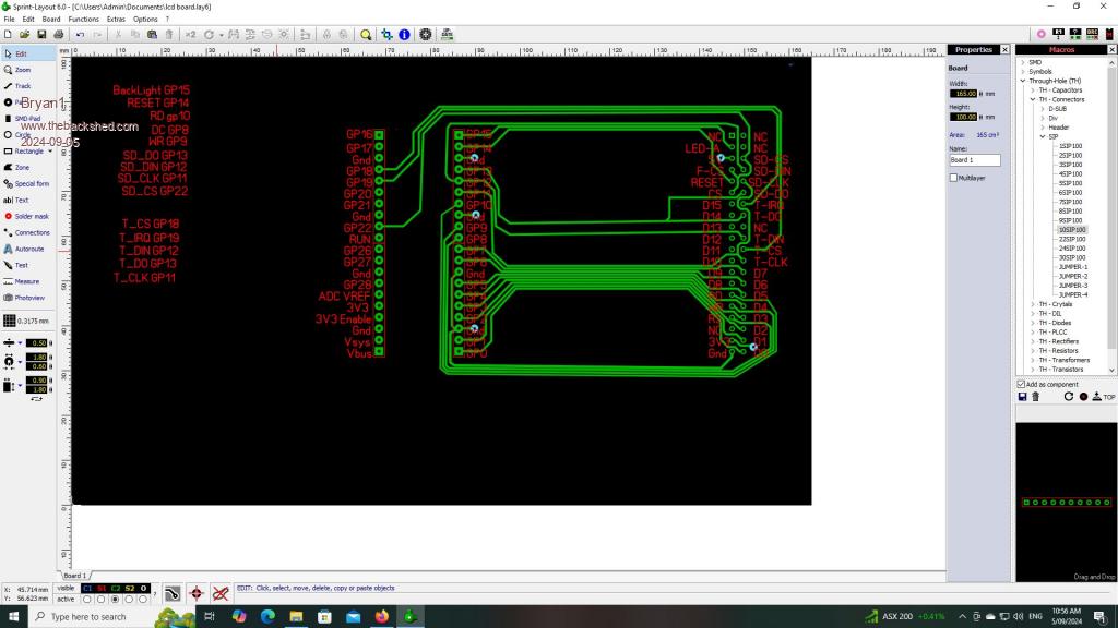 Still a long way to go now with the changes I had to do with the pins hopefully it won't cause any issues. Regards Bryan |
||||
Bryan1 Guru Joined: 22/02/2006 Location: AustraliaPosts: 1343 |
Well just came up to the shed and found I got the header on the LCD backwards  O'well it's all a relearning curve and I do need to make the pico and lcd header a macro time to start again. O'well it's all a relearning curve and I do need to make the pico and lcd header a macro time to start again.Ok saved the pico board and the LCD header as macros and started from scratch  managed to route every pin to the pico manual with only the 5V and 3V3 power lines needing a jumper. So this can now serve as a template as the pins left will be the same for each one. managed to route every pin to the pico manual with only the 5V and 3V3 power lines needing a jumper. So this can now serve as a template as the pins left will be the same for each one.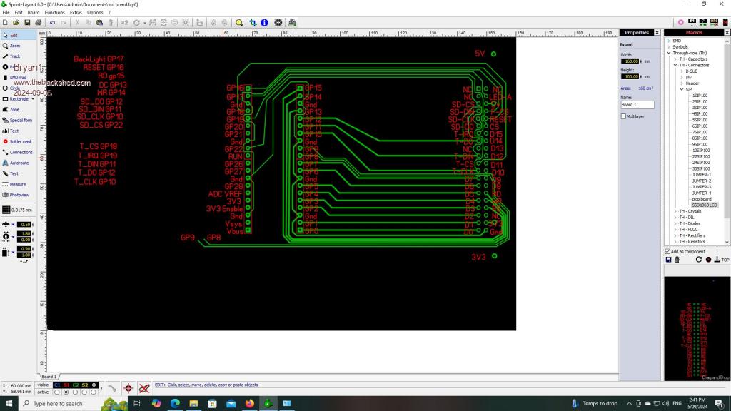 As i'm new to winsucks still need to find a decent zip software that won't try and take over the computer then i can upload the sprint file. Regards Bryan Edited 2024-09-05 15:14 by Bryan1 |
||||
| PhenixRising Guru Joined: 07/11/2023 Location: United KingdomPosts: 855 |
Did you run it through DRC (design rules check)? Might be the screen grab but it looks like some of the traces are a bit close together. |
||||
Bryan1 Guru Joined: 22/02/2006 Location: AustraliaPosts: 1343 |
No DRC check but every track proved good using the test function in Sprint, honestly all last night and most of today I've been playing with this and I'm happy with the challenge set to route every pin to the manual. I found this box to be the right size for the 7" lcd. Now I've been thinking just how to power this and that head torch I scored at work may just fit the bill. 2 off 3.7 volt 2200mAh 18650 batteries in parallel so I do need to get some 3V3 regulators to setup the 3V3 power rail and just one pin to look at the battery voltage and state of charge then it's a case of sticking on a usb cable to charge the batteries. I am thinking of putting on a sea of holes just so this design can get off to JLCPCB which will be a new learning curve with this software. Regards Bryan |
||||
| PhenixRising Guru Joined: 07/11/2023 Location: United KingdomPosts: 855 |
Therein lies the problem because JLCPCB have their own design rules that your design needs to comply with. Check out the drop-down menus under "specifications". |
||||
| Mixtel90 Guru Joined: 05/10/2019 Location: United KingdomPosts: 6765 |
That's very important! :) Just because SL6 can do it it doesn't mean that JLCPCB can. Your supply to the panel needs to be short and able to carry a decent current. The backlight can sag the supply rail seriously on any displays larger than 5" if you don't get it right. I'd recommend putting the regulator close to the 3V3 pin and your power terminals pretty close to the regulator input if you can as you don't want it to drop out. If you want to power from more than 5V then use a pre-regulator to get the 5V rail, otherwise there will be too much heat in that area of the PCB. There's no room for a heatsink and you do well to get 2W dissipation out of even a TO220. You can get a thicker trace to the 3V3 pin by running two on opposite sides of the board (do it by drawing the trace, copying it to somewhere, changing the board side then moving it back. That way they are identical and will share the current correctly.) SL6 is terribly addictive... lol Mick Zilog Inside! nascom.info for Nascom & Gemini Preliminary MMBasic docs & my PCB designs |
||||
| PhenixRising Guru Joined: 07/11/2023 Location: United KingdomPosts: 855 |
Tip for Bryan: Being a time-served control-panel builder, I guess I have some form of OCD  But it only takes a bit of practice to achieve a more uniform layout in SL6. I absolutely do not want autoroute because I find this to be quite therapeutic (for want of a better word).  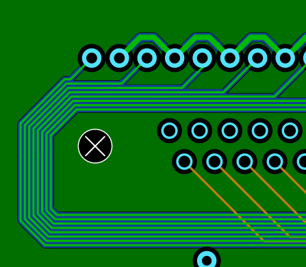 |
||||
Bryan1 Guru Joined: 22/02/2006 Location: AustraliaPosts: 1343 |
Well I am getting there guy's but one does have to eat  Sprint actually does have DRC and I found using the cap macros the DRC was faulting the silk screen on each macro part. So in the end I'm just using pad's in place of the macros parts. Sprint actually does have DRC and I found using the cap macros the DRC was faulting the silk screen on each macro part. So in the end I'm just using pad's in place of the macros parts.It has been well over 10 years since I used Sprint Layout and I'm picking it up pretty quickly and it has been a long day so tomorrow with a fresh mind I'll get the board done. I finally went with that order with Altronics and got some LD1117V33 voltage reg's and O do have a few 7805's here to use. Also I go and see the local battery shop and see what they have for battery packs that I can use. Regards Bryan |
||||
| PhenixRising Guru Joined: 07/11/2023 Location: United KingdomPosts: 855 |
Yeah, I stuck an air-fryer on my desk  |
||||
| Mixtel90 Guru Joined: 05/10/2019 Location: United KingdomPosts: 6765 |
Please, please, please Bryan, pay attention to the current draw of these displays. I'm serious. A voltage drop of 0.1V as you turn the brightness up can shift logic levels enough to screw everything up. You ignore this stuff at your peril - it can make a lovely board useless. Also watch the ground connection(s) to the display. If that lifts because of current draw you are *really* screwed as every data connection will be out of spec. You end up with bits of wire laced over your PCB to try to power the display properly. :( Skinny tracks for heavy loads aren't allowed under any circumstances, no matter how pretty they look. :) SL6 gives you an estimate of the maximum current for a track using 1oz copper but it doesn't take into consideration volt drop along the length of the trace. You will have to de-rate for almost anything other than low current traces. The 5" SSD1963 isn't too bad, but the bigger ones can be a pig. You *have* to have a solid supply to them. If you are powering from batteries don't use a linear regulator. They are inefficient (standing load and temperature dissipation). Get a good buck-boost switcher with plenty of current in reserve to give you 5V. You can use a 3.3V LDO after that if you wish, but a second 3V3 buck-boost switcher from the incoming supply is more efficient. Remember the end point voltage of a 3V7 cell is about 3V. A linear or buck switcher is no good. Mick Zilog Inside! nascom.info for Nascom & Gemini Preliminary MMBasic docs & my PCB designs |
||||
Bryan1 Guru Joined: 22/02/2006 Location: AustraliaPosts: 1343 |
Hi Mick don't worry mate I'm taking all of this in mate and I'm in no real hurry as I just want to do it right. I originally put the 3V3 reg on the left hand side of the board so in the morning I will widen the board to suit the reg right next to the jumper to the 3V3 jumper wire, then the track from the jumper to the pin is less than 5mm. The local battery guy is a great guy to deal with and I have been buying batteries off him for over 2 decades as those N70 batteries only seem to last a few years and my tractor and ol' '95 Hilux unbreakable do take a huge boost to start. Now I reckon 2 of those 18650 batteries in series to bump up the voltage and they go thru a 7805 then the LD117V33. Now these buck-boost switchers are a new thing to me so have you got any link or data on them. Regards Bryan |
||||
| PhenixRising Guru Joined: 07/11/2023 Location: United KingdomPosts: 855 |
I find that; a convenient way to view such devices is to look at the Mikroe Click Boards for a good overview. The actual devices are no-doubt, available for lower cost elsewhere but the Mikroe list makes for convenient comparisons. |
||||
| Mixtel90 Guru Joined: 05/10/2019 Location: United KingdomPosts: 6765 |
You need 3V3 at some point. Getting this directly is worst case. 2x 3V7 (i.e. 18650 not on charge) = 7V4. At 200mA (a guess) you have (7.4-3.3)*.2 = 0.8W dissipation if the reg is 100% efficient (they are nowhere near, so maybe closer to 1W). That's just a little bit too hot to keep your finger on comfortably. If that's a linear reg it's hot. A switcher will be cold. I don't know about availability at your end or what current you will need, but I've used both of these: 4A buck converter 600mA buck-boost converter Both seem to run very nicely and are amazingly cheap. I've had one of the 4A ones powering my aquarium, lights and CO2 solenoid for quite a while now. The main problem is that the PCB holes are fairly large! The little 600mA one can be tweaked to change its output voltage within reason. I've not used it heavily yet, but it's had a bit of abuse while I've been testing. There are loads of others out there. All very easy to use now. . Edited 2024-09-05 23:21 by Mixtel90 Mick Zilog Inside! nascom.info for Nascom & Gemini Preliminary MMBasic docs & my PCB designs |
||||
| PhenixRising Guru Joined: 07/11/2023 Location: United KingdomPosts: 855 |
Too big to upload here so this is my Dropbox: Sprintfont Plugin for SL6 |
||||
| matherp Guru Joined: 11/12/2012 Location: United KingdomPosts: 9090 |
The 5" is actually the worst as it all powers off 3.3V. 7" and up power the screen backlight off 5V and 4,3" is small enough that the 3.3V current draw isn't an issue |
||||
Bryan1 Guru Joined: 22/02/2006 Location: AustraliaPosts: 1343 |
Mick I do have some of these and I got them for my inverter projects. Now my 9 volt to 5 volt breadboard power supply had a flat battery so I just set one of them to 5 volts and it worked a treat. 35 volts max input and they simply use a trim pot to step down the voltage, bought 10 of them so got plenty to play with. Anyway in the past when I used Sprint I only used single sided boards as I used to mill the the designs in my cnc. So this morning decided it was time to learn to do 2 sided boards and man it easier to route all the pins  Decided to do a DRC check and where I simply placed through hole pads on my saved macros the DRC had a heap of errors saying pads too close Decided to do a DRC check and where I simply placed through hole pads on my saved macros the DRC had a heap of errors saying pads too close  . Anyway made new macros for both the pico and SSD1963 using thru hole pads then pasted them into my design and no errors popped up in the DRC. . Anyway made new macros for both the pico and SSD1963 using thru hole pads then pasted them into my design and no errors popped up in the DRC.Regards Bryan Edited 2024-09-06 10:18 by Bryan1 |
||||
Bryan1 Guru Joined: 22/02/2006 Location: AustraliaPosts: 1343 |
Well in to see the battery man this morning and grabbed a 18650 pack so 2 0ff 3450mAh batteries in series with a PCM protection circuit. I dialed in one of those DC-DC boards to 9.6 volts and the battery is charging now 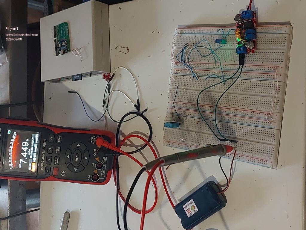 Now a green led shone when the DC-DC board was connected and when I turned on the power to my bench power supply a blue led shone. Just checked and the voltage is up 8.1V so it does look like this DC-DC board can be part of this project then to charge just a DC source higher than the battery voltage will be needed to charge the battery. Regards Bryan Edit: Well 9.6V was too higher a voltage as when the DC-DC board cut off the voltage dropped to 7.4V. So dropped the voltage to 8.6 volts. Now with the input voltage at 12 volts 680mA is the current draw on the power supply so I do think just hooking up the project to a 5 watt solar panel on a sunny day will charge the battery.  I found this little DC-DC boards are quite handy and one is finally being used to do it's job but if one does need a DC voltage this units just work. Edited 2024-09-06 13:14 by Bryan1 |
||||
Bryan1 Guru Joined: 22/02/2006 Location: AustraliaPosts: 1343 |
G'day Guy's, Well that Altronics package arrived today so I did get on make the cut out for that 7" LCD and it fits like a tee to the box. Anyway finally got on to that link Mick put up with those switchmode regulators so ordered 10 each of 3V3 and 5 volts ones. Now would it be the best to feed the 3V3 one with the 5V one or just keep them separate. Also just now got on and started from scratch again and this time got all the connections done to the manual quite easily leaving all the available pins free. Now by using a 10K and 4.7K voltage divider @ 8.4 volts the output is 2.686 and I reckon pin GP8 could be used with this voltage divider to measure the battery voltage. 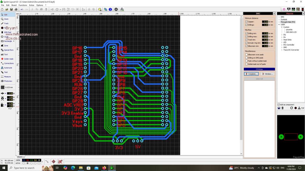 Also found 7-zip so here is the sprint file for this V3 design I'm working on lcd V3.zip Regards Bryan Edited 2024-09-11 18:49 by Bryan1 |
||||
| PhenixRising Guru Joined: 07/11/2023 Location: United KingdomPosts: 855 |
Hey Bryan, I was almost offended  by the "skinny-ing" of the ground trace so I switched it to the other layer(?): by the "skinny-ing" of the ground trace so I switched it to the other layer(?):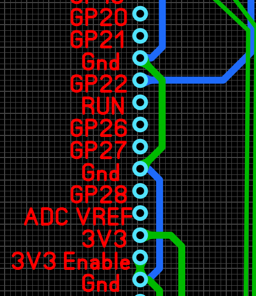 |
||||
Bryan1 Guru Joined: 22/02/2006 Location: AustraliaPosts: 1343 |
Duly noted and changed so thanks mate, still learning here and eh it was under an hour to get that far.  |
||||
| Page 1 of 3 |
|||||