
|

|
Forum Index : Microcontroller and PC projects : Fully portable USB Picomite with MMBasic.
| Page 1 of 2 |
|||||
| Author | Message | ||||
| Bleep Guru Joined: 09/01/2022 Location: United KingdomPosts: 509 |
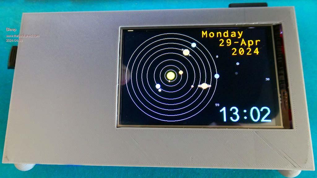 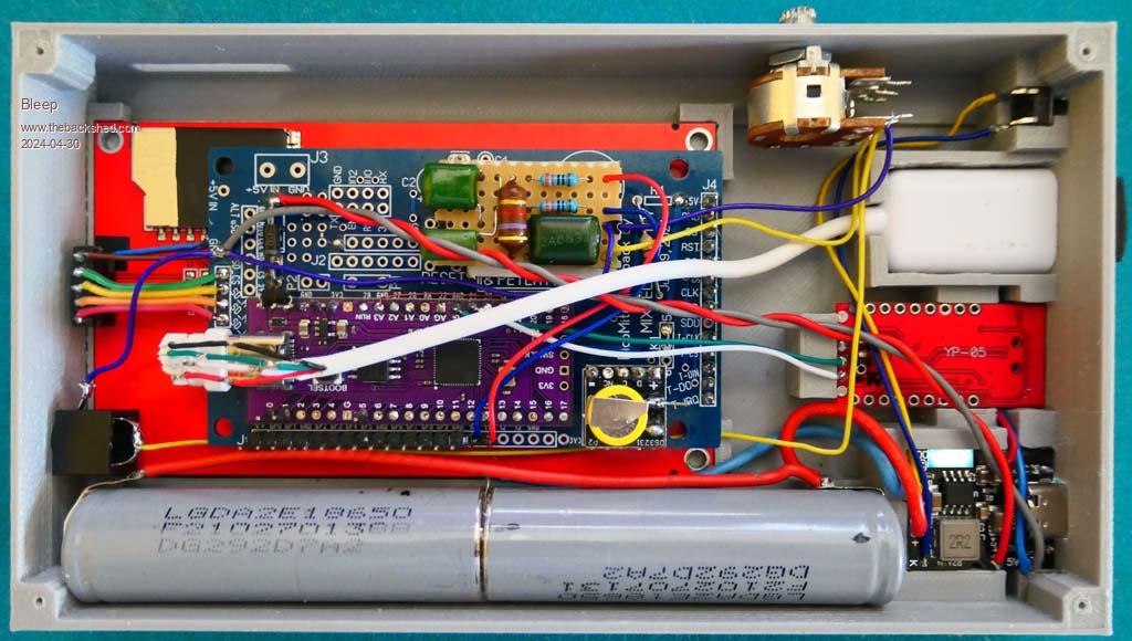 I wanted to build something that would be self contained and fully portable, this is what I came up with. It uses a 4" ILI9488 LCD screen, 480x320 with touch, from AliExpress It has:- USB obviously. Mono sound through a jack plug, with volume, could easily be stereo. Serial to USB. SD card. RTC. All GPIO from GP0 to GP9 are free, coming out to a connector J1 along the bottom edge. All the A/D inputs GP26 to GP28, coming out on connector J2. Can be used as a battery bank when powered on to charge whatever... It uses:- A Chinese Pico, because I wanted the extra flash. One of Mixtel90 backpack boards, mainly as a carrier and for connections to the screen, RTC and SD card. A Lithium battery controller/charger/booster with on-off facility from Ebay A serial to USB converter from Ebay A RTC from Ebay A strip board with Volhouts Audio filter, into which both audio outputs are fed, can easily be made stereo, then on to the 1K potentiometer and output from a jack plug. Other sundry components were 2x Lithium batteries salvaged from a broken LapTop power pack 2.2AHr(measured) each, jack plug, 1K pot, momentary push switch and a box, which I designed up in FreeCAD, unfortunately my printer isn't great, but it has done the job, one slight hiccup was I designed it to have a 1.5mm recess in the back, into which the back plate should have dropped, for a currently unknown reason the printer stopped at exactly 1.5mm from finishing, so the back plate currently doesn't really fit, it sort of sits, but I will at some point make a larger back plate to properly cover the back. (the back plate should only take 30mins, the whole box took 7hrs. For the initial setup and testing everything is only friction fitted, once I'm confident it's all good, I'll hot glue everything, especially the batteries! To operate you press the momentary button once and it all powers up, press twice and it powers down, if you connect to a powered external USB plug, the unit switches over to charging the batteries, as well as powering the unit, only caveat is once you are charging, if you remove the USB cable the unit will shut down briefly and then power back up, better to just leave it charging, then when you want to disconnect, press and hold the button while unplugging the power, it will then stay off, inserting USB power is ok, the unit continues running fine, or powers up if it was off. Battery duration will be about 10 hours, full brightness screen, cpu at 420MHz, or about 20 hours, 50% brightness and 126MHz, or any combination in-between! If you want music, I've experimented and have found compressing to a WAV file, using ADPCM @ 22kHz sample rate works acceptably, so nothing above about 10kHz, not exactly HiFi, but quite acceptable, especially for my ears. The file size is slightly bigger than a MP3 for the same track, so 4.41MB for MP3 and 6.15MB for ADPCM WAV, as opposed to 24.3MB for PCM lossless WAV. The blue light you can see, is infact a 4 bar LED, which gives approximate charge state. More gratuitous pictures:- 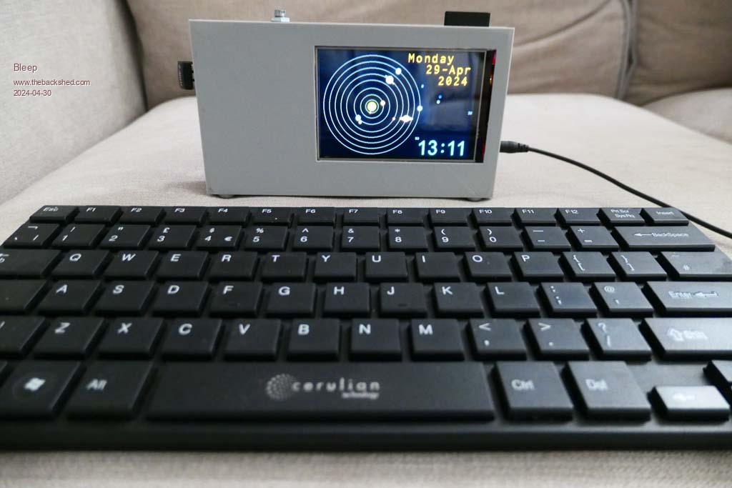 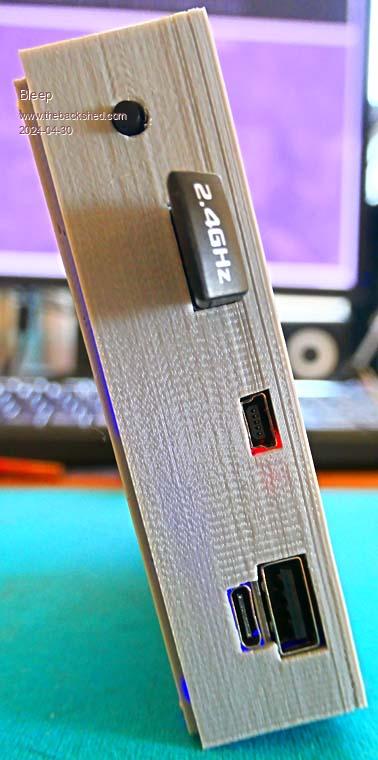 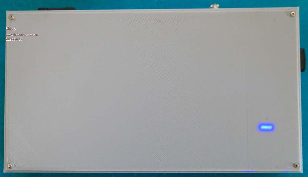  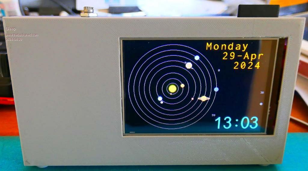 |
||||
| Mixtel90 Guru Joined: 05/10/2019 Location: United KingdomPosts: 6760 |
Very nice! :) Pray tell me, what strange Majik doest hold the display into the case? Art? Mick Zilog Inside! nascom.info for Nascom & Gemini Preliminary MMBasic docs & my PCB designs |
||||
| Bleep Guru Joined: 09/01/2022 Location: United KingdomPosts: 509 |
Friction for the moment, once I'm happy I'll hot glue everything. Regards Kevin. |
||||
| stanleyella Guru Joined: 25/06/2022 Location: United KingdomPosts: 2109 |
Tidy. like the planets. makes space travel look easy. did the case print first go? |
||||
| morgs67 Regular Member Joined: 10/07/2019 Location: AustraliaPosts: 75 |
Hi Bleep Do you have any stl files available to print the box as I would like to copy your setup? -Tony |
||||
| Volhout Guru Joined: 05/03/2018 Location: NetherlandsPosts: 4213 |
Very Nice ! It really has everything build in. Mono audio, but that is good enough. And a decent screen. Only the 480x320 is not the "default" resolution that programs are designed for on Picomite. Maybe a similar size 320x240 would be compatible with more programs. A small tip for future builders.. look at the PicoGame frm Geoff, he has (included in the housing) a guide for the SD card. What is your "charger" module ? Does it also support an ON/OFF button ? Volhout Edited 2024-06-10 17:17 by Volhout PicomiteVGA PETSCII ROBOTS |
||||
| Mixtel90 Guru Joined: 05/10/2019 Location: United KingdomPosts: 6760 |
That would be the Pico Gamer , Harm. PicoGAME is one of my designs and isn't a handheld console. :) Mick Zilog Inside! nascom.info for Nascom & Gemini Preliminary MMBasic docs & my PCB designs |
||||
| phil99 Guru Joined: 11/02/2018 Location: AustraliaPosts: 2129 |
Geoff's one is Pico Gamer, published in Silicon Chip. |
||||
| Bleep Guru Joined: 09/01/2022 Location: United KingdomPosts: 509 |
Hi Phil, FreeCad files attached, a warning, I did have to do a fair amount of trimming to make things fit well, but basically it is as in this file. Hi Harm, I have been following your Thermal Camera with great interest. :-) The charge module I used is this:- A Lithium battery controller/charger/booster with on-off facility from Ebay operation is as mentioned above. To operate you press the momentary button once and it all powers up, press twice and it powers down, if you connect to a powered external USB plug, the unit switches over to charging the batteries, as well as powering the unit, only caveat is once you are charging, if you remove the USB cable the unit will shut down briefly and then power back up, better to just leave it charging, then when you want to disconnect, press and hold the button while unplugging the power, it will then stay off, inserting USB power is ok, the unit continues running fine, or powers up if it was off. I'm inclined to agree with you about the screen, having the 4" 480x320 is nice when editing, (which was why I built it, to be taken away, without needing a laptop) but, when running most of the PicoMite software, which is usually set up for 320x240 it can be a hindrance, I do use Peters 'windowed' 320x240 mode, which mostly works, but that can introduce it's own problems. :-( Keep up the good work, here's hoping the new RPxxxx has double the RAM and a few extra PIO processors, all with extra programming steps and a fix for the AtoD would be nice. :-) Regards Kevin. FreeCAD_Files.zip |
||||
| javavi Senior Member Joined: 01/10/2023 Location: UkrainePosts: 194 |
Very nice autonomous device!  And where can I get such a clock program with planets? Edited 2024-06-11 01:04 by javavi |
||||
| Bleep Guru Joined: 09/01/2022 Location: United KingdomPosts: 509 |
See here Picomite Solar System Clock Attached are three versions VGA, 320x240, 480x320. The LCD versions use touch to enable fast forward and backwards of the planets, you can clearly see the alinement of the planets, which the Voyagers used, if you go back to their launch date, see the comments in the code. The equations used are, as far as I can confirm, very accurate, obviously, the actual orbits are out of scale and circular, not elliptical, the bouncing planet, which represents seconds is poor old Pluto, who got evicted and wants to come back. ;-) I've just pulled these from my archive, unchecked, so you may need to fix minor anomalies. Regards, Kevin. SolarSysBAS.zip Edited 2024-06-11 03:50 by Bleep |
||||
| Bleep Guru Joined: 09/01/2022 Location: United KingdomPosts: 509 |
Am I correct in remembering that it is now possible to define the VGA outputs, as long as they are sequential? So I could install the USBVGA version on to my portable PicoMite, then, because I have left all GPIO 0 to 9 free, make a VGA dongle, including appropriate resistors, that connects to GP0 to 5, for example, then define 'OPTION VGA PINS GP5, GP0' and suddenly I have portable VGA Picomite. :-) on which I can also define the LCD screen as a console? Can anyone see any flaws in this, I'll probably go ahead and try it anyway, just to see what happens. |
||||
| Mixtel90 Guru Joined: 05/10/2019 Location: United KingdomPosts: 6760 |
Yes. I've used OPTION VGA PINS and it's ok. :) Page 60 of the manual that I have. OPTION VGA PINS HSYNCpin, BLUEpin Mick Zilog Inside! nascom.info for Nascom & Gemini Preliminary MMBasic docs & my PCB designs |
||||
| phil99 Guru Joined: 11/02/2018 Location: AustraliaPosts: 2129 |
To use GP0 to GP5 it would be:- OPTION VGA PINS GP4, GP0 which puts the 4 colours on GP0 to GP3 and HSYNC & VSYNC on GP4 & GP5. Though to make your adapter compatible with other VGA boards put the sync at the start. OPTION VGA PINS GP0, GP2 Edited 2024-06-13 08:01 by phil99 |
||||
| Bleep Guru Joined: 09/01/2022 Location: United KingdomPosts: 509 |
I've now included a VGA plug, so by changing the firmware I can use either LCD or VGA firmware. Only problem I had was with the built in SD card reader on the LCD, I eventually had to add a jumper to either connect the SD MISO directly to the Pico, when using the VGA option, or via the LCD when using that; I beleive this is because of the extra diode/resistor required for this LCD, which was upsetting the SD when the LCD was not in use, all other connections stay as they are. 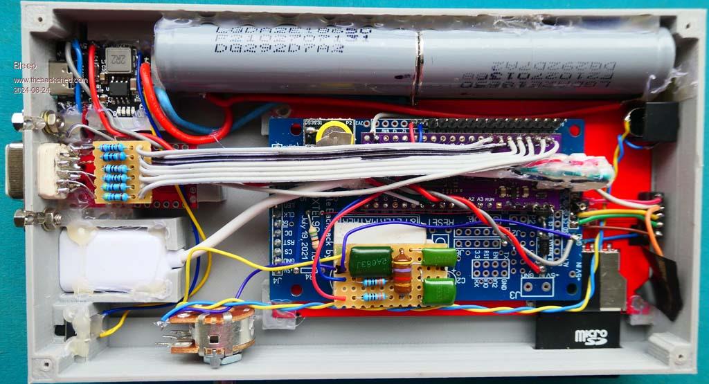  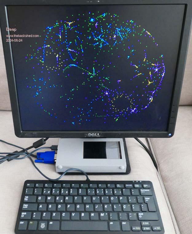 |
||||
| phil99 Guru Joined: 11/02/2018 Location: AustraliaPosts: 2129 |
Yes, the idle state of the LCD_CS Pico pin is high when when the LCD Option is set, acting as a pullup and floating when VGA is set. Many SD cards require MISO to have a pullup but diode leakage is acting as a pulldown, so when using VGA use:- SetPin LCD_CS_pin, DOUT Pin(LCD_CS_pin) = 1 And you won't need the jumper. Edit Option 2 Not visible in the photos, I assume you have removed R8 (4.7kΩ pullup on SD_SDO) from the 4" IPS display, as suggested by me. Later I found R8 pullup can be left in place if the resistor from LCD_CS to MISO is reduced to 1.5kΩ or 1.8kΩ. Reinstating R8 would allow the SD card to work without the jumper or SetPin work-arounds. R8 doesn't have to be 4.7kΩ. Eg if R8 = 10kΩ the LCD_CS to MISO resistor could be 1.5kΩ to 3.3kΩ. Also R8 doesn't need to be a SMD on the display. Any point on the MISO line to 3.3V will do. Edit 2 Tested it and SD card now works whether ILI9488 LCD is enabled or not. The PCB must have needed quite a bit of surgery to get the Purple module pin layout to work! Edited 2024-06-24 11:59 by phil99 |
||||
| Mixtel90 Guru Joined: 05/10/2019 Location: United KingdomPosts: 6760 |
He started off with a great PCB though. ;) Yep, the purple one is an awkward layout, though OK if you simply want the maximum amount of IO and are willing to do a custom PCB. It's one that I avoid. Mick Zilog Inside! nascom.info for Nascom & Gemini Preliminary MMBasic docs & my PCB designs |
||||
| Bleep Guru Joined: 09/01/2022 Location: United KingdomPosts: 509 |
Hi Phil, Thanks very much for the info. :-) Now I know it can be got going in both versions I'll experiment a bit more & let you know, I have removed the pull ups, but as you say they are easily replacable, however, unfortunately I can't now change the 10k resistor, as it's on the other side of the LCD board, which is now glued in place, though I can wire a parallel resistor on to Micks blue board to get roughly between 1k5 & 3k3... 3k9 looks just right :-) Yes wiring in the purple board to tie up with Micks layout was... interesting, I managed to do it, reasonably neatly, by cutting lengths of thin enamelled wire, some longer than others depending on routing, cleaning & pre tinning the ends, then soldering them all to the purple board, then very fiddly getting all the opposite ends into their appropriate holes on the blue board and soldering them as I went, in the end it all works and there is only about 2mm between blue/purple boards, & it looks neat, almost impossible to change anything of course. :-( I'll let you know how I get on. Regards Kevin. |
||||
| phil99 Guru Joined: 11/02/2018 Location: AustraliaPosts: 2129 |
Perhaps you don't need to. As long as the pullup is about 3 to 4 times its value the voltages should be ok, so 27k to 39kΩ should work with 10kΩ. |
||||
| Bleep Guru Joined: 09/01/2022 Location: United KingdomPosts: 509 |
Hi Phil, I've been unable to get any resistor combination to work for both VGA & LCD, without disconnecting the MISO, I've tried leaving the Resistor/diode on the LCD as is and use 22k to 39k pull ups, I also tried putting resistors in parallel with the MISO resistor on the LCD to change its value to values in the range 1k5 to 1k8, with 4k7 pull ups, nothing appears to work reliably for the VGA, without going back to disconnecting the MISO. So I'll probably leave it as is, I'll have to open up the case to be able to press the boot button to reflash anyway, so I can move the jumper at the same time, it's a bit of a shame, but it works. Regards Kevin. |
||||
| Page 1 of 2 |
|||||