
|

|
Forum Index : Electronics : MOSFET question....
| Page 1 of 2 |
|||||
| Author | Message | ||||
Grogster Admin Group Joined: 31/12/2012 Location: New ZealandPosts: 9306 |
Hello all.  I have a circuit, that works very well, that I need to modify a little and am wondering if I can do it with a simple addition of a cap. Here is the relevant part of the circuit: 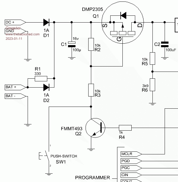 When SW1 is pushed, it pulls the gate of Q1 low, switching it on. R2 keeps the MOSFET firmly in the OFF state otherwise. When SW1 is presses, power is supplied to the rest of the circuit via S-D of Q1, and a Micromite chip. The very first thing the Micromite chip does, is set an output pin high connected via R4 to the base of the NPN transistor, which keeps the circuit powered, even if you let go of SW1. When the circuit has done it's thing, it simply sets the output pin low, which turns off Q2, which allows the gate of Q1 to return high, which turns off the juice to the entire circuit - no standby current at all. Simple enough. I now need to port this design to the PicoMite, as I simply can't get hold of enough MM2 170 chips due to the current silicon chip shortages, and that is all fine, but the PicoMite has about a 3s "Boot-up" time that I need to deal with. If I just use the circuit as above, the circuit will power-down as soon as you let go of SW1, so I need to keep the circuit "On" for about 3s or so, till the PicoMite starts, and can then set a pin high to hold the circuit on in the normal way via Q2. My first thought was something as simple as a cap across the gate of Q1 - such as 1uF or so to ground. Would that work do you think? My thoughts are simply that pressing SW1 will switch on Q1 and a cap across its gate would mean it will take a little time to recharge via R2 to the point that the gate is high enough to turn Q1 off again. That's the idea. I don't have a spare one of these PCB's available, so I am just trying to play with the idea in theory inside my head. Do you think that would work? Perhaps I don't need 1uF as gate current is essentially zero - it is the voltage potential that the MOSFET cares about, so maybe I can get away with a much smaller cap? 100n perhaps? Thoughts? Suggestions? Smoke makes things work. When the smoke gets out, it stops! |
||||
| wiseguy Guru Joined: 21/06/2018 Location: AustraliaPosts: 1156 |
Whilst the addition of a capacitor (and making R2 larger) as you suggest should achieve the required delay it also has some drawbacks. One is that if it has a 3 second hold time when the micro commands it to be off there will be the same 3+ second delay before it turns off. I am assuming this is a production PCB and you wish to achieve the function with as little tacking on of bits as possible ? With a small re-arrangement and adding a couple of parts it can be achieved and function as before - this is just the first idea that comes to mind. After the switch is pressed it charges the 4u7 capacitor to bias the FET Q1 on, whilst the cap slowly discharges via the 680K after the button is released & meanwhile Q2/R4 takes over after boot up. Sorry for the messy sketch which I changed a few times...... R2 does not have to be as low as 10K the 680K to 1 Meg will hold it off just fine. the 4u7 should be a tantalum ideally or low leakage electro. The two extra diodes are 1N4148 etc small signal types. One RC time constant with the 680K is 3.1 seconds so should easily keep Q1 on for 4+ seconds 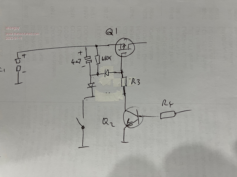 If it is through hole the change is quite simple. Remove R2 and replace with the 680K, solder just end of new R2 closest to D1 (+in) place a diode between the remaining leg of R2 and the hole where it used to meet R3 cut the track from the switch place a diode to the R2 new diode junction other side of second diode back to the switch and solder the 4u7 cap across the new R2 - piece of cake lol. Edited 2023-01-11 19:37 by wiseguy If at first you dont succeed, I suggest you avoid sky diving.... Cheers Mike |
||||
| phil99 Guru Joined: 11/02/2018 Location: AustraliaPosts: 2135 |
Yes that will do the job, though the diode in series with the switch could be omitted and it will still work. One less track to cut. |
||||
| wiseguy Guru Joined: 21/06/2018 Location: AustraliaPosts: 1156 |
Yes Phil 100% correct as you can see by the whiteout I was simplifying but missed one lol thanks for pointing it out before Grog made it ! If at first you dont succeed, I suggest you avoid sky diving.... Cheers Mike |
||||
| CaptainBoing Guru Joined: 07/09/2016 Location: United KingdomPosts: 2075 |
even the micromite 170 based devices have a short boot time (while MMBasic starts and "loads" the runtime environment) which can confuse soft-start circuits like this. I used a similar approach and had to give the instruction "hold the start button until the screen flashes green". When associated code runs, the first thing it does is set the background colour to green and do a CLS. Perhaps a capacitor approach could improve that for me. here is the retrofit circuit i did to add the soft power feature to anything on a tiny 1" PCB. It is nice to have battery powered stuff switch itself off either on command or after a period of inactivity 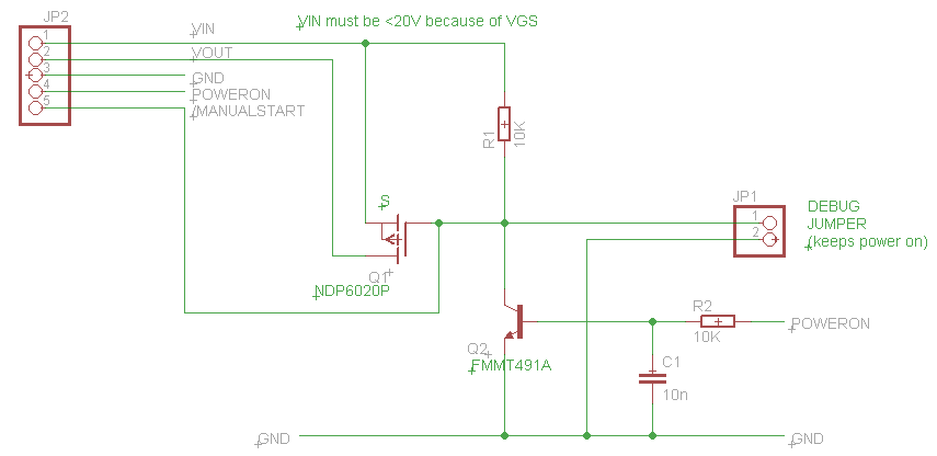 Edited 2023-01-12 03:15 by CaptainBoing |
||||
TassyJim Guru Joined: 07/08/2011 Location: AustraliaPosts: 6098 |
I would make R4 4.7k fed from the micro's power supply (presumably 3.3V). Then to shut down use the micro output to bring the base of Q2 low. It should stay low until the micro runs out of puff but a small capacitor will help prevent a restart. Jim VK7JH MMedit   MMBasic Help |
||||
| wiseguy Guru Joined: 21/06/2018 Location: AustraliaPosts: 1156 |
Clarification may be needed to this comment with regard to the one less track to cut. If it is a PCB mounted switch, the original track/link between the switch and collector of Q2 will still need to be cut. If the switch is off board and connected by a wire yes the track does not need to be cut and the switch wire can be joined directly to the neg side of the 4u7. †These suggestions are all without the benefit of ever seeing the PCB track layout or whether SMD or through hole. †If help is required with how best to implement changes simply for SMD happy to assist further - but a pic would be great for the area in question. Ok just checked after posting, DMP2305 is SMD SOT23 so it is an SMD assembly. Tassy Jim also makes a good suggestion if building new, the 1K just wastes energy, 4K7 or even 10K would work fine. Edited 2023-01-12 11:13 by wiseguy If at first you dont succeed, I suggest you avoid sky diving.... Cheers Mike |
||||
Grogster Admin Group Joined: 31/12/2012 Location: New ZealandPosts: 9306 |
Excellent replies - thanks very much chums.  I thought I was SORT-OF on the right track with the extra cap idea, but I never thought of the diode, so that's useful. The circuit is a form of "One-shot". When you press the button, it just wakes up, transmits a message, then powers itself off, so there is no issue with the code simply pulling Q2 low and waiting till the circuit runs out of juice. The key thing is for it to wake up and stay alive long enough to send the message and NOT rely on you keeping SW1 pressed down to do it. As I say, the original circuit works beautifully for the 170 MM2 chip, but I know that the PicoMite needs a few seconds before it starts running code, so I need to be able to accommodate that. There is a 1k bleeder resistor across the 5v regulator output(which you can't see - it's further to the right of the section of schematic I posted), which ensures that the caps on that side of things are discharged when the MOSFET turns the main juice off. Otherwise I discovered that the PIC would not fully shut down, and pressing SW1 again would NOT initiate another transmission, as the MM2 was in a sort of brown-out situation. The 1k bleeder across the 5v and 3v3 regulators fixed that completely.  Smoke makes things work. When the smoke gets out, it stops! |
||||
| phil99 Guru Joined: 11/02/2018 Location: AustraliaPosts: 2135 |
The need for the bleed resistors might be removed by using part two of Tassy Jim's suggestion. A small cap on Q2 B-E could keep Q2 off long enough after shutdown for the rail voltages to decay. |
||||
Grogster Admin Group Joined: 31/12/2012 Location: New ZealandPosts: 9306 |
Here is what I have now, but I am a little mystified by the existence of D3. 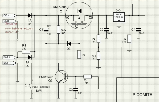 In this setup, D3 will block the positive potential from appearing at the gate of the MOSFET, and so I would expect the MOSFET to be ON forever. Pressing the switch or switching on Q2 will also turn on the MOSFET by pulling its gate low, but with D3 in series with the gate, it will never switch OFF. This is cos with SW1 released and the PicoMite having also pulled the base of Q2 low, D3 prevents the gate of Q1 rising to the point that it switches off - do you see what I am getting at? Perhaps I am not understanding something here, so would love clarification of the purpose of D3. I made R4 4k7, and stole the value of C3 from CaptainBoing's schematic. Smoke makes things work. When the smoke gets out, it stops! |
||||
| phil99 Guru Joined: 11/02/2018 Location: AustraliaPosts: 2135 |
" it will never switch OFF." Yes I see what you mean, but D3 is there to prevent Q2 recharging C1 as that would result in a very long switch-off delay. a 4M7 to 10M bleed resistor across Q1 G-S should discharge the gate capacitance fairly quickly. Experiment on a breadboard. Soldering legs on surface mount components is fiddly but do-able. |
||||
Grogster Admin Group Joined: 31/12/2012 Location: New ZealandPosts: 9306 |
Yes, I think the time has indeed come to experiment on a breadboard.  I will use standard TO92 parts for that. In my application, I don't think the MOSFET choice is that critical - any will do for this kind of thing. Smoke makes things work. When the smoke gets out, it stops! |
||||
| wiseguy Guru Joined: 21/06/2018 Location: AustraliaPosts: 1156 |
Sorry Grog & Phil, I hang my head in shame 2 stuff ups on the same circuit with a whole 3 or 4 components. Next time I will take longer than 2 minutes & check more carefully. The 680K should be directly across the G & S terminals ie the lower end of the 680K should move from the Cathode to the anode of D3. D3s purpose is to allow the 4u7 to charge rapidly by the switch and then "leak" its charge into the 680K resistor via D3 and keeping Q1 on whilst doing so. †D3 also prevents the 4u7 from accumulating charge again when Q2 is on. The 680K in its rightful place will keep Q1 off. Grog said "In this setup, D3 will block the positive potential from appearing at the gate of the MOSFET" The purpose of D3 is to allow the negative charge from SW1 and the 4u7 to turn on the P channel Mosfet which needs negative on the gate compared to the source (+). It also prevents the negative potential when Q2 is on from charging the 4u7 capacitor. The initial statement may be correct but a bit misleading with respect to operation. Better to talk negatives when referring to the gate source voltage of a "P" channel mosfet. Edited 2023-01-12 17:38 by wiseguy If at first you dont succeed, I suggest you avoid sky diving.... Cheers Mike |
||||
Grogster Admin Group Joined: 31/12/2012 Location: New ZealandPosts: 9306 |
No worries, Mike!   Does THIS now agree with what you are saying: 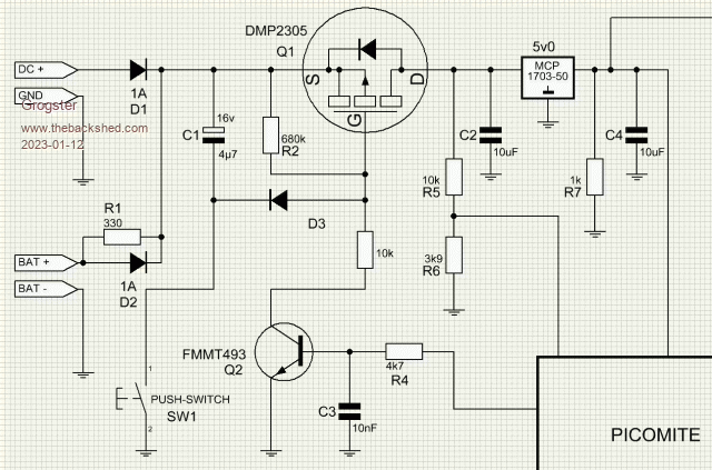 THIS does make much more sense along the lines you have already stated. Smoke makes things work. When the smoke gets out, it stops! |
||||
| wiseguy Guru Joined: 21/06/2018 Location: AustraliaPosts: 1156 |
YES ! - sorry  PS: I rarely use P channel Mosfets they may have a place but they invariably end up hurting my head ! Edited 2023-01-12 17:45 by wiseguy If at first you dont succeed, I suggest you avoid sky diving.... Cheers Mike |
||||
Grogster Admin Group Joined: 31/12/2012 Location: New ZealandPosts: 9306 |
No need to apologize.  Gawd.....the mistakes I have made in my electronic career....   My signature is: "Smoke makes things work. When the smoke gets out, it stops!" My boss when I was an apprentice told me that one, with the added bit on the end that is omitted in my signature: "...and it's very hard to get the smoke back in." One of the reasons for posting this thread, was me not wanting to see that smoke any time soon!  Smoke makes things work. When the smoke gets out, it stops! |
||||
| phil99 Guru Joined: 11/02/2018 Location: AustraliaPosts: 2135 |
With the 680k moved to the gate a bleed resistor is now needed across C1. When Q2 is on it no longer has a discharge path so when Q2 gets turned off the remaining charge on C1 may turn Q1 back on briefly. You could make both R2 and the bleed resistor (R2b) 1M2 or 1M5 and get about the same delay. Also C3 might be a bit small, perhaps 100nF or increase R4 to 47k. Edit Or increase C1 to 10uF then R2 and R2b can be 680k. Edited 2023-01-12 21:26 by phil99 |
||||
| wiseguy Guru Joined: 21/06/2018 Location: AustraliaPosts: 1156 |
Phil do you ever get tired of being right......  FYI I created a post that had 2 x 1.2M as you rightly suggest and then convinced myself only 1 resistor was needed.......unless Q2 turns on  Edited 2023-01-13 00:34 by wiseguy If at first you dont succeed, I suggest you avoid sky diving.... Cheers Mike |
||||
Grogster Admin Group Joined: 31/12/2012 Location: New ZealandPosts: 9306 |
Okey dokey, so how does this look: 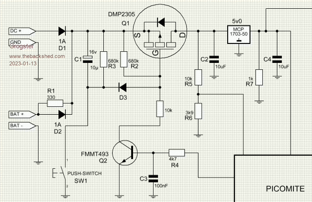 Does that look like it will satisfy all requirements? I plan to make C1 an MLC SMD cap, as I have plenty of those in stock, but I CAN change that for an SMD tantalum if the members think that would be better. I don't really care about EXACT timing, I only care that the MOSFET stays on long enough for the PicoMite to take over and hold the circuit on, so perhaps a tant is overkill? Smoke makes things work. When the smoke gets out, it stops! |
||||
| wiseguy Guru Joined: 21/06/2018 Location: AustraliaPosts: 1156 |
That looks fine now with regard to values and placement (I hope Phil agrees lol). However I strongly advise against using an MLC capacitor for a timing purpose such as this. The reasons are better explained here The value of an MLC capacitor for various appplied voltages are all over the place. For reliability of calculated values matching circuit behaviour, electrolytic or preferably tantalums are the best way to go especially when there are many to be made, its easy to coax a circuit to work but using a different brand/voltage/package has issues. If at first you dont succeed, I suggest you avoid sky diving.... Cheers Mike |
||||
| Page 1 of 2 |
|||||