
|

|
Forum Index : Electronics : Small Toroid Inverter
| Page 1 of 2 |
|||||
| Author | Message | ||||
Bryan1 Guru Joined: 22/02/2006 Location: AustraliaPosts: 1344 |
G'Day Guy's, I have this frequency converter here with 40x80x20mm toroids and there are 3 of them. The wire is 2 inhand 1.6mm and with all connected in series 0.37 ohms 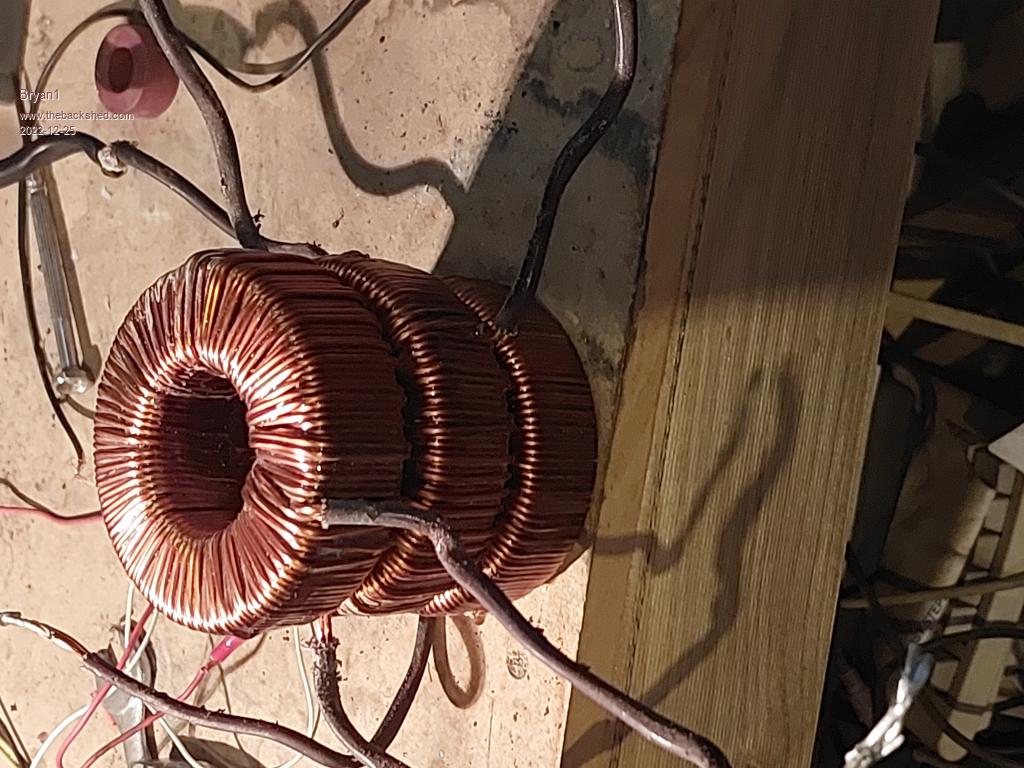 So do you guy's reckon this could be a candidate for small inverter, now I do have a bag of 10 irf3205 fets here and a couple of 1500uf 420 volt DC caps. Cheers Bryan |
||||
| Murphy's friend Guru Joined: 04/10/2019 Location: AustraliaPosts: 648 |
Hi Bryan, you're a bit stingy with information here. Do you want to build 3 small inverters or one 3 stack core inverter? If is a 3 stack then you need to unwind all the wires, epoxy the cores together to make one tall one, figure out the turns/volt for a 1 Tesla (10,000Gauss) flux and go from there. How to go about that is all explained in warpspeeds old topics. I made a small test inverter with an E-core transformer, which had suitable windings, I had here. It just managed a 150W floodlight load. One of your little cores might not even manage that little power. Those caps, you'll need two, a quarter the voltage and 4 times the capacity to do any good. Don't forget you need a choke too. Is this for something to do to keep you busy or do you *need* a small inverter? If it's the latter then it might be wise to see first what's available on Ebay. The amount of work involved building a little inverter is way out of proportion to building a big one for the acquired power handling. |
||||
Revlac Guru Joined: 31/12/2016 Location: AustraliaPosts: 1024 |
Those cores you have, may not be silicon steel? Something this small is not really worth the effort, just an example this is roughly the same size, this little 10VA transformer that was used in traffic lights 240VAC to 10VAC, might make a choke out of it, but even then there is not much room in the centre. 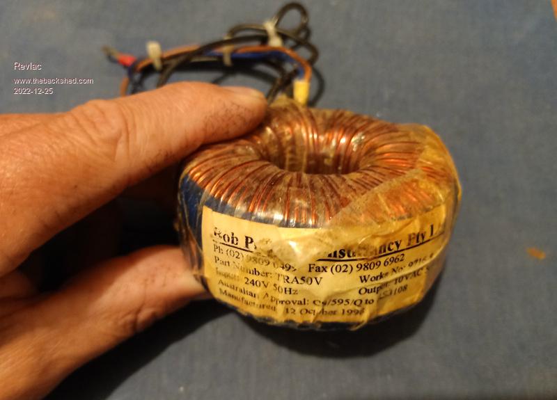 Edited 2022-12-26 09:34 by Revlac Cheers Aaron Off The Grid |
||||
Bryan1 Guru Joined: 22/02/2006 Location: AustraliaPosts: 1344 |
G'Day Guy's, I decided to rip out that EI transformer from that forklift battery charger which on the plate says 60 amps output from a 240 volt 10 amp supply into a 24 volt battery. 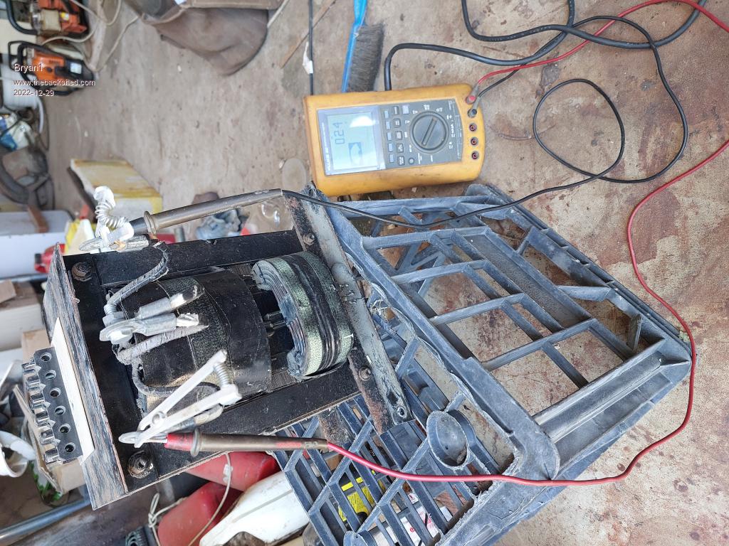 Now the top section is 8x5mm copper and the lower section is 2.5mm copper wire 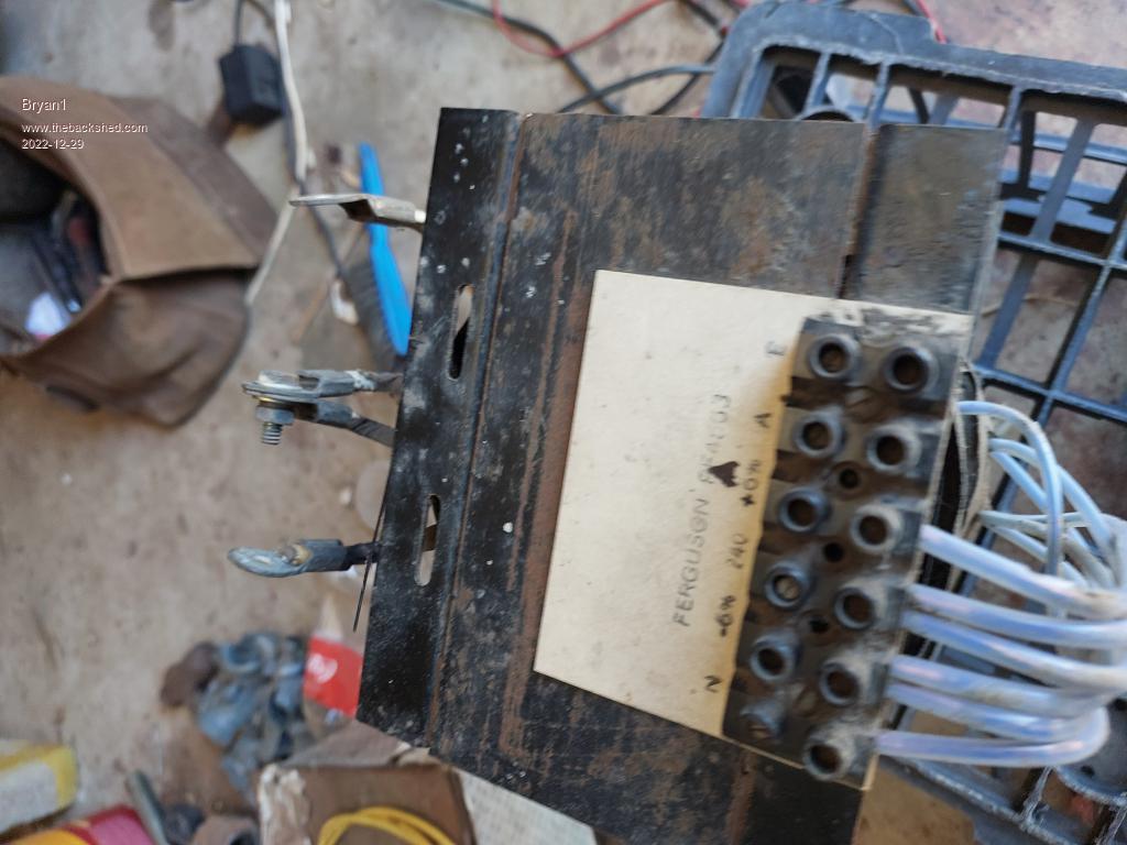 This transformer does weight around 30 kg's at a guess so the question is would be a contender ? Cheers Bryan |
||||
Revlac Guru Joined: 31/12/2016 Location: AustraliaPosts: 1024 |
2 problems to start with. The center part between the 2 windings should come out if possible. Also it would need to be rewound primary over secondary. Could you get a photo of the center section? looks like there is a weld on the side. Edit no. 2 Also while it is connected, can you measure how many watts it is using? Edited 2022-12-29 15:11 by Revlac Cheers Aaron Off The Grid |
||||
Bryan1 Guru Joined: 22/02/2006 Location: AustraliaPosts: 1344 |
Hi Aaron yes there is a weld holding the upper and lower section together 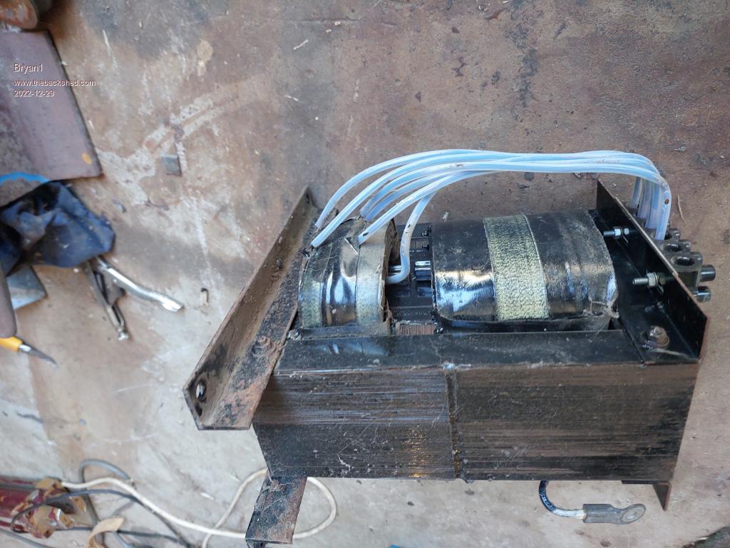 I went off a link to the inverter board off a thread here and found it was unobtainable so went on a search and found one for $94 + shipping where looking thru the whole part I did see they had some pics of EI transformers as the input. I would need to look again to to find it but as I will need to get one it will have until the new year. Also I put in for a quote for new toroid where the option is there to wind it with copper for the secondary. Can't do any watt measurements as when I got this battery charger the main circuit was cactus and besides I got it for free. I do have a couple of 5kg spools of 1.6mm copper wire so if needs stripping out and starting from scratch I reckon this unit will fit the bill for the project. The windings are all potted so it will be a quick job with a 5" grinder and the 8X5mm will be saved for the dancing spark plugs I make and sell and the 2.5mm wire will do some nice bends too. Cheers Bryan Edited 2022-12-29 16:09 by Bryan1 |
||||
| phil99 Guru Joined: 11/02/2018 Location: AustraliaPosts: 2135 |
Note the magnetic shunts between primary and secondary. They give the primary a lot of extra inductance and reduce the coupling to the secondary making it more like a constant current source when heavily loaded. Punch them out (large bolt, big hammer) and it becomes a regular constant potential transformer. |
||||
Bryan1 Guru Joined: 22/02/2006 Location: AustraliaPosts: 1344 |
You know the more I think about this it would be a great time to setup my forge and melt enough transformer core to cast my own toroid, just need to make a pattern. Got quite a few old cores here and I do think casting my own then machining it should get me over the hurdle of not finding a toroid. The old mind boggles.... Cheers Bryan |
||||
| phil99 Guru Joined: 11/02/2018 Location: AustraliaPosts: 2135 |
A solid core is a short circuit, has to be laminated with thin insulation (usually just oxide) between surfaces. |
||||
Revlac Guru Joined: 31/12/2016 Location: AustraliaPosts: 1024 |
I agree with Phil, Knock those bits out between primary and secondary. Bryan, The Toroid cores are made of silicon steel sheet, not solid steel. If you could test the idle current of that transformer, that will give as a little info on it an weather its worth while to continue. Winding this type of transformer to about .8 tesla should give low idle current (if it isn't already) but it would still need a choke to help with that. Peak efficiency might be 80-85% at best, but it would be very easy running for the mosfets. The wire sounds good, but it depends on how much trouble it is to get it apart. Toroids are getting fewer and far between unless you buy a new core, This EI would make a good test unit or a backup inverter, depends Weather you go with it or not, what is the dimensions of it, center leg Cross section etc? Anything els you have in your shed?  Cheers Aaron Off The Grid |
||||
Bryan1 Guru Joined: 22/02/2006 Location: AustraliaPosts: 1344 |
Down at the house now so testing for idle current would be hooking up my cheap dmm to the input side then putting my fluke 865 meter on the AC side with no load to see the output while using my spare subi batteries for the 24 volt source rather than use my 24 volt 735 AH battery Edited 2022-12-29 18:38 by Bryan1 |
||||
Revlac Guru Joined: 31/12/2016 Location: AustraliaPosts: 1024 |
I would feel a little safer if could be plugged into an energy meter, for reference a few transformers I tested a long time ago were about 7watts & 240vac but on a smaller core. I think the cores where 52cm square, but cant find my notes. Edited 2022-12-29 19:26 by Revlac Cheers Aaron Off The Grid |
||||
Bryan1 Guru Joined: 22/02/2006 Location: AustraliaPosts: 1344 |
G'Day Guy's, Well just did a test and sacrificed some 6mm cable as it was a dead short, so basically a rewind would be needed. The dimensions are 170mm wide X 230mm high x 85mm thick and each side is 28mm typical. So now the thoughts turn to a heap of research on going about rewinding this to suit an inverter. Cheers Bryan |
||||
Bryan1 Guru Joined: 22/02/2006 Location: AustraliaPosts: 1344 |
Ok first thought bubble strip out everything just leaving the outer core then grind some radius's on each side and the ends. Then wrap the secondary around just like one would with a toroid then the primary can be wound over. So would this iron laminate get enough magnetism going to get a decent output. So thoughts on Pro's and Con's are very welcome as this would be an interesting project to do if worthwhile. Cheers Bryan |
||||
| phil99 Guru Joined: 11/02/2018 Location: AustraliaPosts: 2135 |
The size, shape and magnetic shunts are almost the same as a 2kW discharge lamp ballast-transformer I converted to a 1:1 isolating transformer many decades ago. Which makes sense as a ballast-transformer and charger-transformer need to provide a more or less constant current into a load that does not have a positive resistance. After the rewind it could deliver about 2.5kW continuous. I kept the original primary, punched out the shunts and cut away the secondary. The original arrangement deliberately limits the coupling between the primary and secondary. To improve coupling I slid the primary to the middle and put a 120V secondary on each side, connecting them in series. Rather than grinding off the corners of the center limb (which would reduce the cross-section), to protect the new winding from the corners I wrapped the center limb with a couple of layers of thick paper and masking tape. For an inverter the original primary becomes the secondary, with the primaries on either side wired in parallel. For parallel connection both must have exactly the same number of turns. To work out the turns required put a temporary 10 turn secondary on with 240V ac on the primary and measure the output. Edited 2022-12-30 17:14 by phil99 |
||||
Bryan1 Guru Joined: 22/02/2006 Location: AustraliaPosts: 1344 |
G'Day Guy's, Well as the end of day was on the way finally got more shed time so cracked a pale ale and went to work stripping this old transformer. I had it all apart with still half a stubbie left  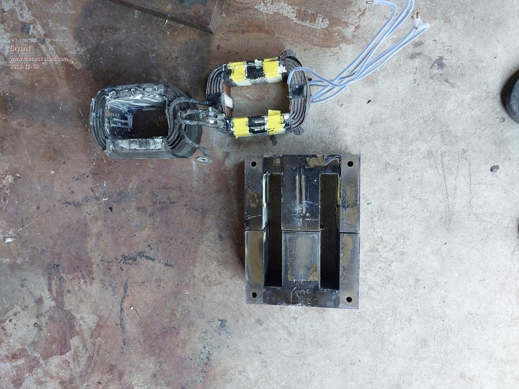 Now the centre boss is 58mm thick and there is 28mm of winding height so my thoughts are now wind the secondary on the E-core by using a former to wind the wire so it can then slip into the E-Cores then get welded back together also wind the primary over the top ensuring the 28mm height is kept in check. So if I can pull apart the old secondary with the 8x5mm wire that can be used as the new primary and just put some heatshrink over the wire to ensure isolation. Cheers Bryan |
||||
Revlac Guru Joined: 31/12/2016 Location: AustraliaPosts: 1024 |
Well that come apart easier than I expected,  Yes a former will be the way to wind it, shame it Couldn't be tested for idle consumption, will be back later. Cheers Aaron Off The Grid |
||||
Revlac Guru Joined: 31/12/2016 Location: AustraliaPosts: 1024 |
170 x 58 =9860, so 98.6cm square, not sure if thats correct but got to start somewhere. A calculator here https://www.electricaltechnology.org/2014/02/maximum-flux-density-bmax-calculator.html Enter values RMS Voltage : 240 Frequency : .00005 Mhz Number of Turns : 140 Core cross section : 98.6 Then press calculate and it should give the Tesla value. 140 turns don't sound like much? You may have to adjust the number of turns to suit the the amount of space you have on the core, even layers covering the full window height is best if possible. Tony could explain this better if he were here. The paper between the winding layers might be reusable. Been a long day So I might have stuffed some of that up.  If the window height is 170mm and 28mm wide, using 2.5mm wire, that would make 68 turns per layer but I doubt that many would fit per layer, you would have to work out what what fits evenly. Edited 2022-12-30 21:27 by Revlac Cheers Aaron Off The Grid |
||||
| phil99 Guru Joined: 11/02/2018 Location: AustraliaPosts: 2135 |
From the dimensions given:- "The dimensions are 170mm wide X 230mm high x 85mm thick and each side is 28mm typical." and "the centre boss is 58mm thick and there is 28mm of winding height" I take it to mean the cross section of the centre limb is 85mm x 58mm = 49.3 Sq cm. the magnetic path length is (28/2 + 28 + 58/2 + 230 - 28) x 2 = 54.6 cm Using 49.3 sq cm, 360 turns, 240V, 10A = 6091.28 Gauss. Not knowing what the B-H curve for the iron is I don't know if 6000 is too high. 2 turns / volt might be safer than the 1.5 I used. |
||||
Revlac Guru Joined: 31/12/2016 Location: AustraliaPosts: 1024 |
Yup, I thought something wasn't right with my figures, good to have another set of eyes to check these things. Cheers Aaron Off The Grid |
||||
| Page 1 of 2 |
|||||