
|

|
Forum Index : Windmills : Physical/Hydraulic/Electromechanical Braking of Turbines?
| Page 1 of 2 |
|||||
| Author | Message | ||||
| Kamak Senior Member Joined: 13/04/2021 Location: CanadaPosts: 150 |
Has anyone here ever experimented with braking of wind turbines? Physical/Hydraulic/Electromechanical Braking of Turbines? Electromagnetic...etc Edited 2021-04-20 02:08 by Kamak |
||||
| Kamak Senior Member Joined: 13/04/2021 Location: CanadaPosts: 150 |
Controllers help reduce speed along with dump load resistors, but what about full stop, and locking for maintenance? |
||||
| Technophiliac Regular Member Joined: 18/12/2020 Location: New ZealandPosts: 92 |
I understand the common thing is to simply short out the 3 phase wires (assuming that to be your scenario?) puts a large drag on spinning - try it! Some people like to slow them before stopping using slowing resisters and fancier options no doubt exist. Davo, Wellington. You can have it perfect, on time, and at the best price. Choose any two. |
||||
| Kamak Senior Member Joined: 13/04/2021 Location: CanadaPosts: 150 |
Yeah, that's the idea for slowing them down. I was thinking about using a motorcycle brake/car brake to stop and lock it. Is there no way to utilize more of the voltage range output for charging batteries? Some kind of voltage regulation that allowed a larger input voltage range? |
||||
| Kamak Senior Member Joined: 13/04/2021 Location: CanadaPosts: 150 |
. Edited 2021-04-21 04:51 by Kamak |
||||
| Kamak Senior Member Joined: 13/04/2021 Location: CanadaPosts: 150 |
Just what the Dr ordered? Edited 2021-04-21 06:20 by Kamak |
||||
| Kamak Senior Member Joined: 13/04/2021 Location: CanadaPosts: 150 |
OK, I now have a method of steady rpm/power. I have only to get a reliable tack set up to read the rpms. I bought a crappy cheap digital noncontact tack, but it is so bad in daylight, it doesn't even work. the environment needs to be shaded and all reflective surface needs to be blacked out, except for the small stuck on a piece of reflective tape. But as long as the frequency is below 200hz, I can calc it as: 200hz/24 full waves per rev. x 60 = 500rpm? |
||||
| Kamak Senior Member Joined: 13/04/2021 Location: CanadaPosts: 150 |
A new method of steady-state measurable RPM. 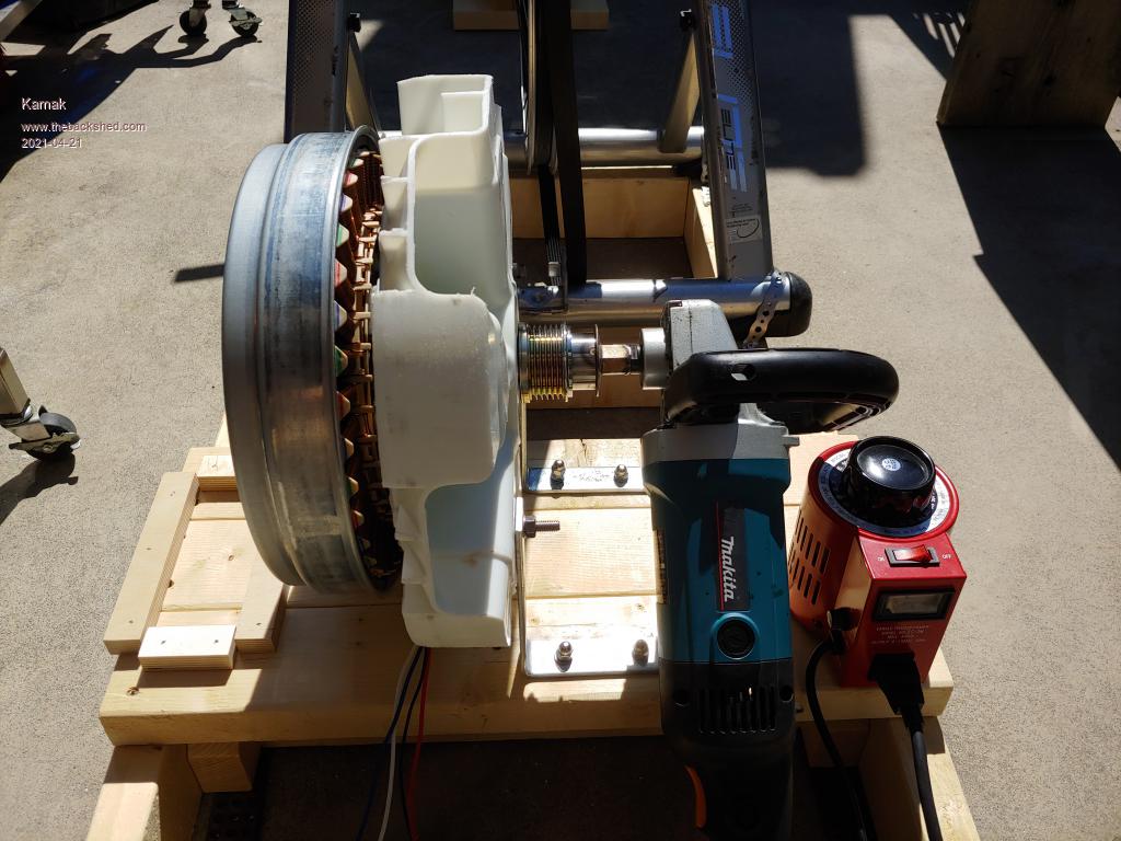 Edited 2021-04-21 09:28 by Kamak |
||||
| Kamak Senior Member Joined: 13/04/2021 Location: CanadaPosts: 150 |
185hz = 462.5 rpm 185/24 pole pairs x 60sec. = 462.5rpm 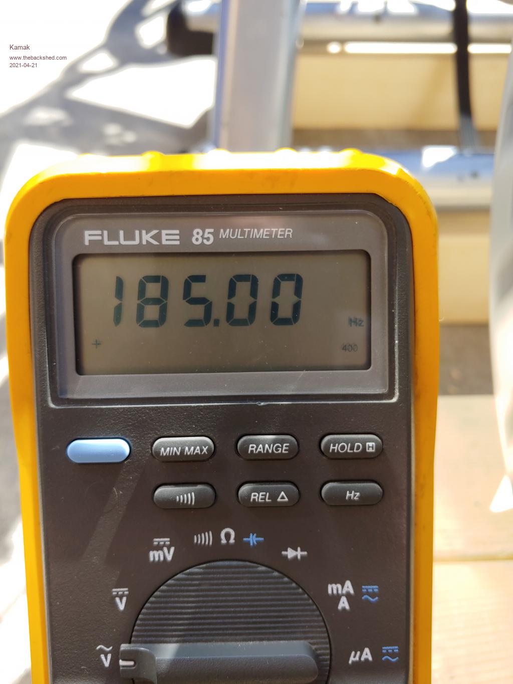 |
||||
| Kamak Senior Member Joined: 13/04/2021 Location: CanadaPosts: 150 |
The stock voltage Vp output of one phase at 462.5rpm. 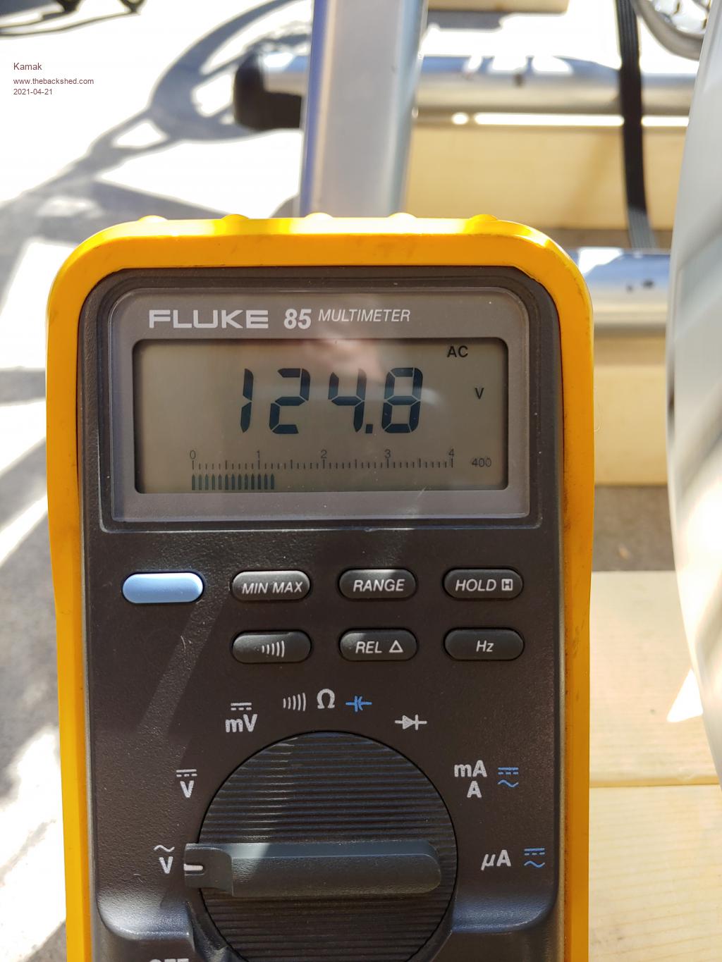 |
||||
| Kamak Senior Member Joined: 13/04/2021 Location: CanadaPosts: 150 |
Crimped on a common point connection. 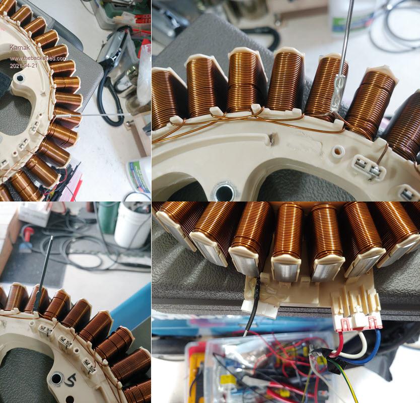 |
||||
| Kamak Senior Member Joined: 13/04/2021 Location: CanadaPosts: 150 |
Ah dang, I put these pics in the wrong thread. See now this is why we need to be able to delete sh*t. lol Oh well |
||||
| kitestrings Senior Member Joined: 23/04/2014 Location: United StatesPosts: 102 |
To answer your original question. Yes. I've dabbled around with wind turbines for a long time. When younger, I worked for a turbine manufacturer who made induction, line-synch'd turbines. We tested and manufactured some with electro-mechanical brakes (that smell of burning discs still takes me back), hydraulic brakes, 'dynamic' electric brakes, and even tip-brakes, which deployed at the tips of the blades in over-speed. Some worked better than others. Most were unsatisfactory. We've taken a different approach with our turbine. I favor those with passive furling, so ours has side furling. For a long time we had a hand-winch that allowed it to be manually furled from the ground. A few years ago I set it up to operate with a motor actuator. It will run off the CC, or manually, and everything is at the base of the tower. I've posted about it on Hugh's and OP. It has worked really, really well for us. Best, ~ks |
||||
| Kamak Senior Member Joined: 13/04/2021 Location: CanadaPosts: 150 |
Nice work on the furling idea. How about eddy current/magnetic drag brakes, something like how exercise equipment use aluminum discs rotated through a magnetic field of a permanent magnet assembly. As the permanent magnets are brought closer to the disc, more drag is created. I'm not really sure there would be enough drag created to withstand high winds. How does the furling work? It swings the tail fin perpendicular to the rotor blades causing the rotor to go out of alinement with the wind direction? That's how I pictured it. I've never yet really research it. |
||||
| kitestrings Senior Member Joined: 23/04/2014 Location: United StatesPosts: 102 |
The axis of the rotor is offset. It swings the tail parallel to the plane of the blades (which I think you meant) yes, or vice versa, and because the hinge is angled, gravity always tries to restore it to the unfurled, operating position. There's a pretty good description of furling here: http://www.thebackshed.com/windmill/Docs/Furling.asp The problem with electrical braking IMO is that it puts a lot of strain on things, but also when you need most - say a gale force storm - you may not be able to rely on it. Wind is unforgiving. It seems I did post on ours here (I'd forgotten). I'll try to update it, there have been a few tweaks, but the basics are here: https://www.thebackshed.com/forum/ViewTopic.php?TID=9674&PID=107116#107116 |
||||
| Kamak Senior Member Joined: 13/04/2021 Location: CanadaPosts: 150 |
Ah yes, there would be definitely stress on the shaft as the braking is applied in ever-changing high winds. Getting the rotor blades into an offset position would be the best way to lower torsional stress on everything from the blades to the shaft, even the tower, I suppose. Though I think a clever person could automate quite easily and on some reasonable budget, a vehicle brake to stop/lock the rotor, once it has slowed down. The idea I have in my head about the aluminum disc/permanent magnet variable drag mechanism is that it could be automated, positionally/proportionally to apply rotational drag as the rotational speed goes out of a specific range, always keeping the rotor speed below a dangerous threshold. |
||||
| Technophiliac Regular Member Joined: 18/12/2020 Location: New ZealandPosts: 92 |
The problem of electrical loading using dump loads during excessive wind is the excessive heat generated in the coils with photos of overheated burned out coils not too hard to find on the internet all be it on cheaper turbines. Anyone considered water cooling the coils during excessive wind periods to protect the coils from overheating? An electric solenoid water valve could open to allow water to spray the coils to cool them perhaps triggered by voltage generated? Internals would need to become water friendly. Taken to the nth degree hot water drained off might be stored and used?! Davo, Wellington. You can have it perfect, on time, and at the best price. Choose any two. |
||||
| Kamak Senior Member Joined: 13/04/2021 Location: CanadaPosts: 150 |
Yeah, those standard off-the-shelf dump-load resistors actually have a hollow core, which could facilitate water circulation. But that's a complicated setup on a tower 30+ feet in the air. I wouldn't use a dump load resistor to control rpm speed. I want to use an eddy current aluminum disc with a linear actuator/permanent magnet design. the magnetic flux drag phenomenon that occurs within aluminum, I believe, creates less heat generation, and to my knowledge seems to create a lot of torque. The question I still have is, how much torque can be created with disc masses, diameters, and magnets of reasonable sizes? 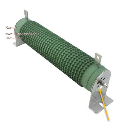 There is something very cool about this auto-belay design that makes it self-contained and automated through centrifugal force and proximity to the magnets. Though that is complicated and has only one setting at a specific adjusted time, and probably can only accommodate a small range of adjustment within its confined volume. https://headrushtech.com/climbing It's basically a fall arrester that accommodates a wide range of user weight and maintains a set rpm 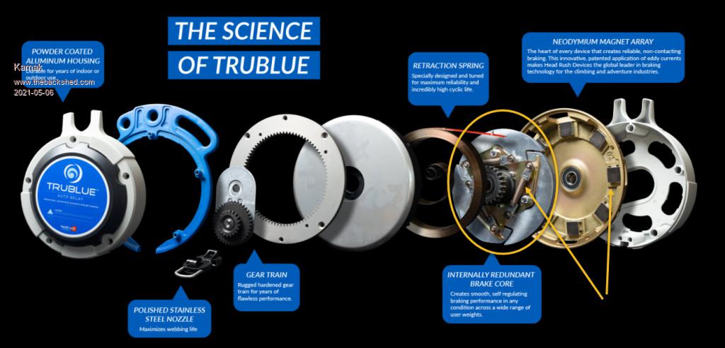 I think I would prefer to pursue an investigation into the use of linear actuated magnetic proximity. Based on the rpm. This way the turbine rotor would have zero applied brakings until a threshold was reached, thereafter, real-time fast response of the linear actuator would maintain rpm, very accurately. This approach would only accommodate a small range of turbine generators of a maximum size of X. If it could be used for 2KW and smaller I would be interested in investigating. 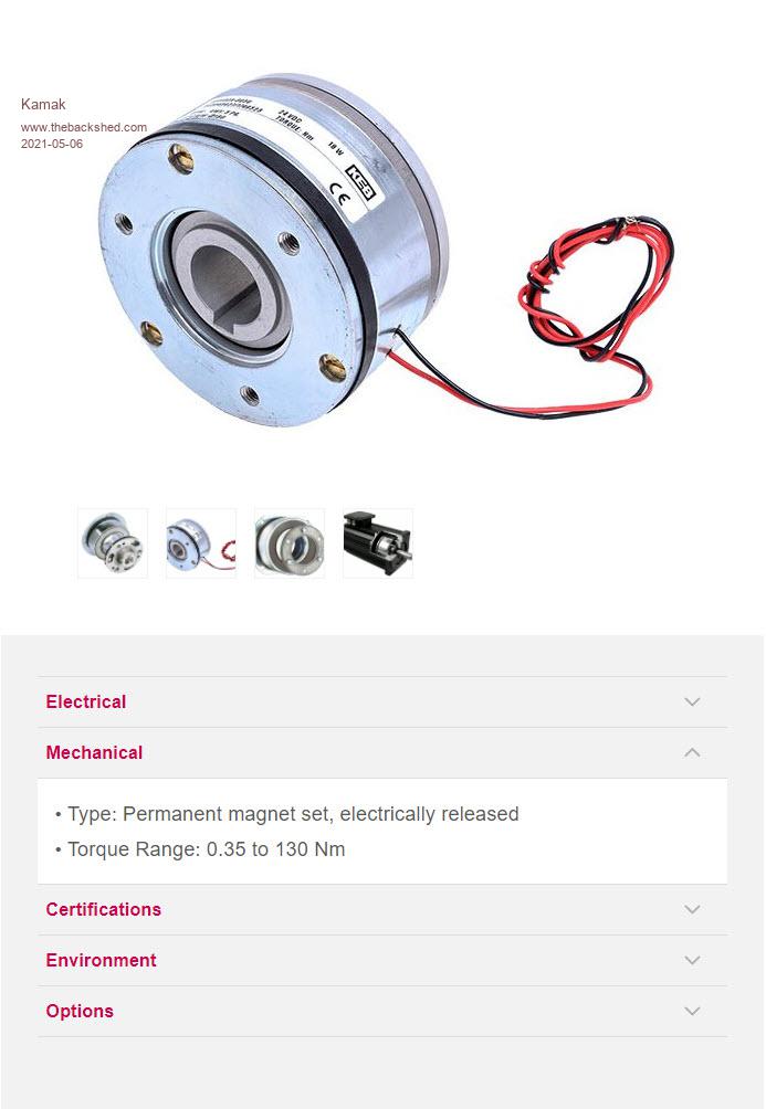 This off-the-shelf design is either on or off. I want proportional I don't want to use the generator, "regenerative braking" because I don't want to interfere with its purposeful usage. I want it to be either generating power to charge batteries or heating water, or it's off. A stand-alone speed controller/brake, is the best option. Edited 2021-05-06 02:52 by Kamak |
||||
| Kamak Senior Member Joined: 13/04/2021 Location: CanadaPosts: 150 |
Ozwindengineering https://www.thebackshed.com/forum/ViewTopic.php?FID=2&TID=6884#72475 This is just a physical friction-style brake, with a physical pull/application leaver, ie rope. I would only use such a device for "locking/stoping" the rotor, not for proportional speed control. Edited 2021-05-06 04:26 by Kamak |
||||
| Kamak Senior Member Joined: 13/04/2021 Location: CanadaPosts: 150 |
Eddy Current Absorber Brake/Clutch |
||||
| Page 1 of 2 |
|||||