
|

|
Forum Index : Electronics : Power Supply Upgrade.
| Page 1 of 4 |
|||||
| Author | Message | ||||
| Phil23 Guru Joined: 27/03/2016 Location: AustraliaPosts: 1664 |
Hi All, Planning on upgrading the old power supply I built as a teenager.... Plan on using a DPH3205 Module I've bought. Don't really remember the size of the transformer, just that it's good for at least 5 amps & the rectified DC is about 25V. The Cap after the Bridge is 20,000uF; probably because that was impressive to a teenager, (not sure where I got it). Don't recall the actual circuit, but there's an LM317, a TIP32 & a pair of 2N3055's on a heat sink. I do remember the 2N3055's were an essential as I like the look of a pair of them on a heat sink. (Nerd version of a set of wide shiny wheels). Main question I have, is can I just drop the new module in across the bridge & cap & leave the old stuff in place. Sort of like the immediate control you get from a Pot in some circumstances; quick changes & instant analogue feedback on the gauges... Thanks Phil 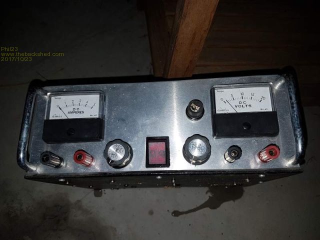 And Opp's I left it out & it rained yesterday; standing draining.... The left Pot does nothing; I was going to be current limit, but that never happened. 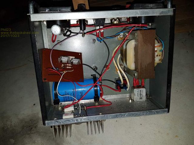 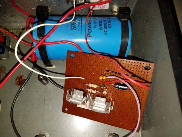 That big fat Cap was irresistible as a Teenager... But still needed a couple of T-03 packages on a heat sink for external Bling... 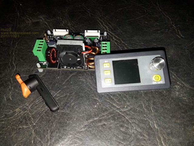 Earpiece is just there to indicate the size of the two modules. |
||||
| Alastair Senior Member Joined: 03/04/2017 Location: AustraliaPosts: 161 |
Phil, Why do you want to change it? What can't it do the you need? The advantage of what you have is that it is linear and should be free of switching noise. If you add the device you are proposing it will have noise that you will have to watch. Like you I built a simple linear power supply as my first real project when a teenager. Transformer, variable regulator, 3055 booster, big output cap, dual sweep meter for volts/current ex aircraft from surplus store. Later added current limiting with a 317. Recently added fixed slave linear regs for 3.3/5/12v and digital meters all mounted in plastic boxes on the outside of the original wooden boxes. Works well but I had to put a lot of work into filtering out the noise from the digital stuff I had added. Not pretty but functional. I have a couple of new clever supplies but still reach for the old one first. My point is think carefully before changing it. Perhaps make a secondary box with the new bit that just links to the old box so you still have the clean linear when needed. I hate hash on supply lines and have been caught in recent times by issues from el cheapo power supply modules from you know where. cheers Cheers, Alastair |
||||
| Warpspeed Guru Joined: 09/08/2007 Location: AustraliaPosts: 4406 |
Have to agree... The old brute force linear regulators are pretty bullet proof, and if it does melt down, very simple and easy to fix. A super super high tech switching power supply and microprocessor controller are fine, until the smoke comes out. What are you going to do then ? Cheers, Tony. |
||||
| Ralph2k6 Senior Member Joined: 24/09/2017 Location: AustraliaPosts: 129 |
You can certainly use the newer module in tandem with the old system. Of course its likely expecting pretty clean DC, so a couple of smaller caps on the input as well as the huge one would help ensure smoothing. The new unit I think will be stand alone only, unless you hack into its controls. Despite the HF noise they appear to be very nice units. Wonder if a ferrite on the output leads would smooth the output much. Ralph |
||||
| Phil23 Guru Joined: 27/03/2016 Location: AustraliaPosts: 1664 |
It does have a fairly big toroid on the output; LHS in the above pic. Phil. |
||||
| Warpspeed Guru Joined: 09/08/2007 Location: AustraliaPosts: 4406 |
I am in the market for a couple more bench power supplies right now. I looked at these fairly low cost 30v 5A supplies on e-bay. They look pretty good until you scroll down and start reading all the warnings about how easy they are to blow up. http://www.ebay.com.au/itm/Precision-DC-Power-Supply-Variable-Digital-Lab-0-5A-0-30V-Adjustable-Voltage/351833409526?epi d=6005526243&hash=item51eae7c7f6:g:CGUAAOSwdzVXt1dv A further look at what was on e-bay came up with these simple kits. The advantage of a kit is you get a full schematic, its all made from very common low cost through hole components, and the ICs can be fitted into sockets. If it does blow up it should then be pretty simple to repair. https://www.ebay.com.au/itm/0-30V-2mA-3A-Adjustable-DC-Regulated-Power-Supply-DIY-Kit-Precision-Variable-Lab/40116717086 6?hash=item5d676d3d32:g:qdMAAOSwtnpXqEMi Cheers, Tony. |
||||
| Alastair Senior Member Joined: 03/04/2017 Location: AustraliaPosts: 161 |
Tony, following your links shows just how many power supplies there are on the market. Many are really very cheap for what they purport to offer. The warnings you noted highlight a common issue for me, that most supplies have a single on/off switch which turns off the mains. I wish they would also have an OUTPUT on/off so you can have the unit powered up, voltage set and then switch the output as required. This would also solve the problem noted as a risk for these supplies. The kits you found look quite good and are attractive because they appear to be largely linear as far as I can tell. The downside is you don't get the nice box, meters and switch gear which is hard to make to the same standard at home. What about modifying the original one with a small relay so it does not enable the output on power up and can be arranged so that it disconnects the output quickly and avoids any reverse voltage? Cheers, Alastair |
||||
| Warpspeed Guru Joined: 09/08/2007 Location: AustraliaPosts: 4406 |
Yes they are a linear regulator and will require an ENORMOUS heatsink and possibly a fan to work properly. I am fortunate that I already have a couple of dead power supplies that have the enclosure, transformer, meters and so on already there. Just needs the blown up circuit board repairing, which is a really ugly inaccessible mess and for which I have no schematic anyway. Its all just too much trouble to trace it all out and fix. Its going to be much easier for me to just rip all the existing guts right out and replace it all with one of those kits. Bench power supplies take a hell of a beating. At least they do around here. It would be sad to spend eighty bucks or more on something that dies fairly quickly and then is not repairable. I don't know how large the enclosure of those e-bay switching power supplies is, but probably far too small to rebuild it as a linear supply with a transformer and large enough heatsink. If I was starting completely from scratch, I think I would build two or three of those linear supplies into an old computer case with an aluminium front panel. Panel meters are pretty cheap, add some ten turn potentiometers, and monster heatsinks across the back, and it could end up looking rather nice. Cheers, Tony. |
||||
| Alastair Senior Member Joined: 03/04/2017 Location: AustraliaPosts: 161 |
Tony, We have the same genes   I am growing to dislike switchmode power supplies as much as Grogster is developing antibodies to Win10 !! I recently built a near copy of a digital gadget that I made last year. The first work flawlessly. The new one was flaky and the logic was miss triggering. Ended up being spikes on the 5v supply. Same little power module as I had used before but the recent one had different brand caps on the output which were rubbish. Cheap fix but wasted a lot of time. Now it is the first thing I check. Slow learner. cheers Cheers, Alastair |
||||
| Warpspeed Guru Joined: 09/08/2007 Location: AustraliaPosts: 4406 |
I used to design commercial switching power supplies before I retired. They are truly wonderful things, as long as the loads they work into are clearly defined. They can also be noisy and fragile and can go *BANG* very easily causing catastrophic damage that can then be difficult or impossible to repair. These days with really small unmarked surface mount components, and multilayer circuit boards, tracing out a non functioning circuit can be just about impossible. So whatever goes bang can then become a disposable throw away item. A bench power supply needs to be simple, easy to repair, and built like brick dunny. End of rant ! Cheers, Tony. |
||||
| Tinker Guru Joined: 07/11/2007 Location: AustraliaPosts: 1904 |
My bench power supplies are linear, home made ones. I do have a DC/DC converter add on that boosts 12V in to up to 80v out, great for inverter testing. But, regarding the output switch idea, my supplies do not have one. I just disconnect the load. Too simple?? Klaus |
||||
| Alastair Senior Member Joined: 03/04/2017 Location: AustraliaPosts: 161 |
Klaus, Fair point and it is what I do with a supply that does not have a switch. Typically when I am using a bench supply it is for prototyping and I usually have a rat's nest of wires on and around a breadboard and other bits. Easy to make a mistake with many wires or disturb something. My last project I had 3 supplies going - 3.3v for the MM+, 5v for the relays and 15-20v to simulate a solar panel. Only one supply, my home made old one, had a switch. Just a preference not a big deal. alastair Cheers, Alastair |
||||
| Warpspeed Guru Joined: 09/08/2007 Location: AustraliaPosts: 4406 |
I just use the mains on off switch on my linear supplies to disable the outputs when testing. Cheers, Tony. |
||||
| Alastair Senior Member Joined: 03/04/2017 Location: AustraliaPosts: 161 |
I worry about transients and settling with the switchmode units. I have tried measuring them with a scope - the reality does not seem too bad but .... My old linear is fine but I have a switch there anyway. Cheers, Alastair |
||||
| Pete Locke Senior Member Joined: 26/06/2013 Location: New ZealandPosts: 181 |
My first power supply I built from scratch, was when I was picking apples. Many hair cuts ago, when I used to have hair. As an ex T.V tech, the locals soon found out I used to fix broken shi...er....electronic things. The stack of car radios and the like meant a supply was needed. So into Dick Smith to supplement the second had stuff I had on hand. It was only a 1 amp supply, but enough for small things. That was 1984. It's still going and my main small supply for bench work. Just went out and took the lid off it to see what I had made. Regulator is based on a 741 op-amp. Not sure of you can still get those. Volt meter was an old V.U meter re purposed. Outlet cables are an old multi meter. The only new things bought were the box, the pot and the main smoothing cap. The main regulator transistor is from a dead TX-574 frame output (hands up if you know what that is  ) but it runs well. ) but it runs well.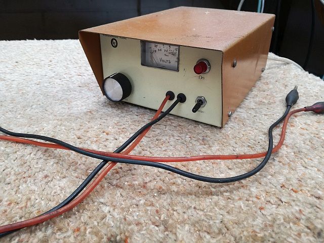 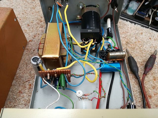 Sorry to hijack the thread, but 'Bush Construction' of such things should be proudly shown off  |
||||
| Warpspeed Guru Joined: 09/08/2007 Location: AustraliaPosts: 4406 |
Great effort there Pete, and I bet it has been as faithful and reliable as an old dog. I believe that is definitely the best way to go. The postman just delivered my two $12.50 do it yourself thirty volt three amp e-bay bench power supply kits. It looks like pretty good value, although no schematic or detailed instructions were included. All I received through the post was a bag of bits and nothing else. Component values are printed on the circuit board, so it's no trouble to assemble. There are even plugs and sockets and extender wires included for the potentiometers. It all looks to be rather good value. I am in the process of tracing out the circuit and reverse engineering it right now before I start to assembling it. Initial impressions are highly positive. Cheers, Tony. |
||||
| Warpspeed Guru Joined: 09/08/2007 Location: AustraliaPosts: 4406 |
O/k I have assembled one of my two e-bay linear power supply kits, and am pretty impressed with how well it works. The only reservation I have is the enormous power dissipation under continuous short circuit conditions, which amounts to about 32v dc at the full three amps rated current limit. The single NPN bipolar power transistor supplied with the kit (2SD1047E) will struggle, even with the largest fan cooled heatsink. Its rated at only 100 watts dissipation at 25C junction temperature. Its toes are right on the line for safe area operation, the dc curve limit is 3 A at 32 volts. It really requires two devices in parallel, but that is going to be a physically very messy solution. I did blow up one transistor torture testing it to destruction, it shorted unsurprisingly, and also took the 0.47 ohm 5W current shunt with it. A much better solution would be to use a really large mosfet instead of the 2SD1047. Its a direct physical swap without any other changes. The advantage is that mosfets do not suffer from second breakdown effect like bipolar transistors, they don't go into terminal thermal runaway when they see both high voltage and high current together. Any hot spot goes high resistance in a mosfet, and so the current spreads very evenly through the mosfet die. The hot spot causes current to crowd in a bipolar transistor, so the hot spot gets hotter and smaller, and hotter still. Then it just melts and shorts out. Its a highly unstable condition. One moment its just running a bit hot, then it suddenly fails shorted. Both the 2SD1047E and my mosfet use the same TO-247 package, it drops straight in, and it works great ! Just about any large mosfet will work, it needs a high power dissipation rating, meaning a large silicon die, but the actual voltage, current, and Rds on are not really relevant. As long as its a big Mutha, with lots of rated watts it should be ideal. I used an FDA50N50 which is 50A, 500v and rated 625 watts dissipation (at 25C junction). Something I already had here and not too expensive on e-bay. That should be pretty well indestructible. Now about half way through assembling the second kit. The big advantage of these kits are that they are a basic easy to repair linear supply, with a robust double sided circuit board, large pads, tracks and holes, easy to trace out the schematic, and simple to work on, using large common garden variety through hole components. These days commercial power supplies are very likely to use a fiendish switched mode board, with multilayer surface mount construction, and small unidentifiable difficult to source components, and the chances of fixing it without a parts list and schematic would be just about zero. Home brewing is not going to save you dollars if you need to buy everything. But it can definitely be quickly resurrected if the smoke escapes. Cheers, Tony. |
||||
| Alastair Senior Member Joined: 03/04/2017 Location: AustraliaPosts: 161 |
Tony, Looking good. I like the idea on swapping out the bipolar for a mosfet. Good that it was such an easy swap. I have been waiting for you to comment on the end product. Whilst I do not need another power supply now, I am wondering if in a few years something like you bought may not be around. Might buy one for a rainy day. Cheers, Alastair |
||||
| Warpspeed Guru Joined: 09/08/2007 Location: AustraliaPosts: 4406 |
Its not bad. It regulates well and has good transient response, and no vices at either turn on or turn off. The output goes right down to zero, in fact down to about -50mV. The kit would be quite usable as is, provided the load is very quickly disconnected if/when it shorts out if the current limit is screwed all the way up to the full three amps. It only has a problem if you want to use it as a three amp current source feeding a very low impedance load continuously. There is also provision on the board for a three terminal regulator. They supply a 7824 +24v regulator in the kit, as a fan supply. But that could be replaced with a 7812 for powering a couple of digital panel meters (plus the fans). Its all there, it just needs a 24v 3A transformer, big heatsink, fan, and panel meters and you are set to go. Cheers, Tony. |
||||
| Alastair Senior Member Joined: 03/04/2017 Location: AustraliaPosts: 161 |
OK - sold. Cheers, Alastair |
||||
| Page 1 of 4 |
|||||