
|

|
Forum Index : Electronics : OzInverter OzCntrl PCB rev12 Sept2017
| Page 1 of 13 |
|||||
| Author | Message | ||||
| Clockmanfr Guru Joined: 23/10/2015 Location: FrancePosts: 429 |
Hi 'Oztules' and guys. September 2017 and the New PCB has all the latest up-to-date modifications. Thanks to Madness for asking 'Oztules' some clarification questions. Here are some screen Photos of my latest OzControl Number 12 PCB board, with all 'Oztules' and gangs amendments. My boards are slightly different than Oz's original's as in the very beginning I wondered away on a different path. But its pretty well Oz's design. Its 5mm higher/width and 18mm longer, so now 90mm by 187mm. Longer for getting that big extra 2uf capacitor on neatly, with flexibility on deferring sizes with the AC voltage sence transformer. 'Oztules' a couple of questions..... I see with your latest board, 12v supply and 5v supply, you have changed 4.7uf to a 10uf any reason?. ....... Up near the Thyristor there is a diode to the LED, fr101, is this critical? If you can check my circuit over for howlers it would be appreciated. If okay I will have some made up and put one on test. Then I will post the Gerbers Zip File on here. Nice design Oztules and thanks. 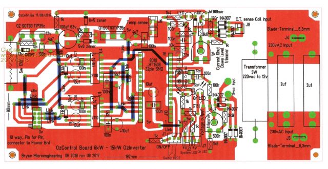 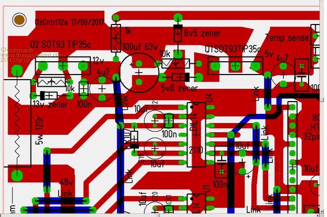 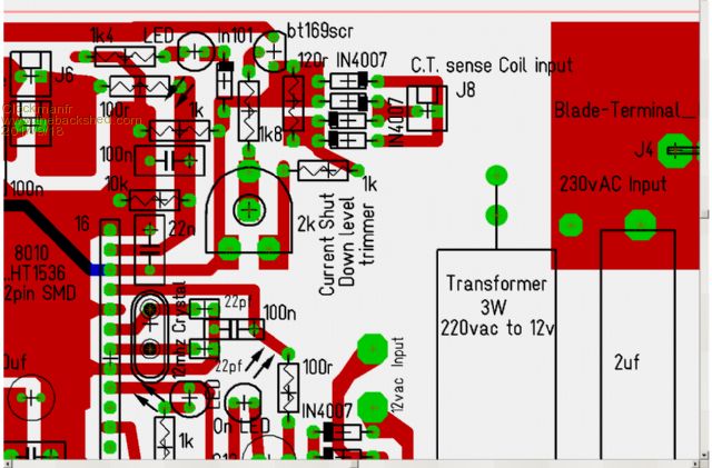 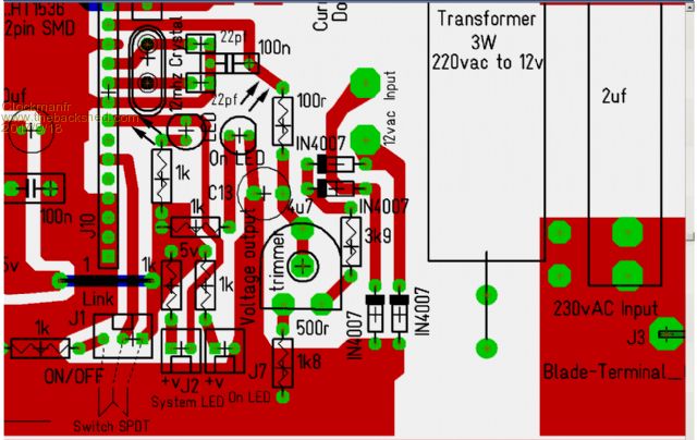 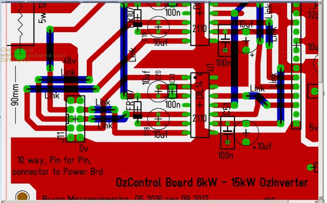 Everything is possible, just give me time. 3 HughP's 3.7m Wind T's (14 years). 5kW PV on 3 Trackers, (10 yrs). 21kW PV AC coupled SH GTI's. OzInverter created Grid. 1300ah 48v. |
||||
oztules Guru Joined: 26/07/2007 Location: AustraliaPosts: 1686 |
A quick look seems to show it is ok. The 3k9 may need changing depending on the tranny. Diode may be anything you have , it is only blocking from memory. 4u7 10uf ... whatever you wish, bigger is better perhaps ... I had a lot of 4u7 left over from something else. Just cannot get any time at the moment to progress on things.... to many island breakdowns for various things.... no not inverters thank goodness, although did fix up a 5kw HF Samil GTI inverter the other day.. interesting, blown output stages, and then a dc inj high fault.. all good now.... looks like they clamp the fets at zero crossing to stop any DC getting into the mains.... just a guess really, but fixed anyway. Mad, I had to back off the 25 pwm... it pulled the battery up to 57v in the end... had to go to 5. I also stuffed up the addition of your code, and moved a brace one position... then the absorb used the last pwm setting if the voltage dropped below 57v... sad syntax me. All good now... but it did not show up on sunny days.... so took a while before I noticed it. Clockman... a few small changes in the solar pwm board, to do with power supply damping, and getting the divider better...better fet driving conditions etc... will get there soon I hope with a final board. Folks who spice everything...... miss out on a lot of fun I reckon.... why spice it when you can get hours of fun blowing things up  ..........oztules Village idiot...or... just another hack out of his depth |
||||
Madness Guru Joined: 08/10/2011 Location: AustraliaPosts: 2498 |
Hi Oz, Yeah I had issues with the code too sorted it yesterday, I will post on that thread. Tomorrow I have some time to try out the new control boards, the transformers I have are 9V so will start out with a 2K resistor and see how that behaves. You really should be reported to the RSPCM! There are only 10 types of people in the world: those who understand binary, and those who don't. |
||||
oztules Guru Joined: 26/07/2007 Location: AustraliaPosts: 1686 |
This is the wrong thread to do it.... but ...Clockman may be interested too. When I fixed the 5kw Samil tls inverter.... it was my first chance to try a transformerless GTI inverter on an ozinverter..... so just hooked it up and waited for the bang.... it started perfectly, and climbed up to 1450 watts on a 1.5kw array... did not make any faults or any queer start up or fusing problems... just worked out of the box so to speak.... no matter what I tried with them, they worked flawlessly together. It never ceases to amaze me just how solid these inverters have become... your initial foibles not with standing.. they are just rock solid no matter what you throw at them, I am continually amazed at what they will do for a a $1.50 chip.... absolutely gobsmacked really. I have not killed a single HY4008 as yet... simply amazing considering how I treat them. ........oztules Village idiot...or... just another hack out of his depth |
||||
Madness Guru Joined: 08/10/2011 Location: AustraliaPosts: 2498 |
I posted the GTI stuff on the other thread as I thought this one is about inverter control boards. My initial problems with the HF GTI was I did not have the correct size breaker on the AC (this is prior to trying to control it). The HF GTI I am using runs completely silent and cooler than the Aero-sharp. Much easier to mount on the wall too. Clockman please look here for further info regarding Charge Control. There are only 10 types of people in the world: those who understand binary, and those who don't. |
||||
| Tinker Guru Joined: 07/11/2007 Location: AustraliaPosts: 1904 |
My experiments found that the EG1810 is looking for a voltage between 2.5 - 3.0V at the VFB input. Anything outside that and it blinks a fault. So, any small transformer from 4.5VAC to 12VAC secondary voltage will do. Just select the first dropping resistor so the pot input sees a max of 4 Volts. You certainly would not want to accidentally feed more than 5VDC into VFB. Looking at the board Clockman posted above I see there is a 1K8 resistor from the low end of the pot to ground. This complicates the dropping resistor calculation. If it was me I would short this 1K8 resistor so the low end of the pot is at ground level. For example, I use a 15K dropping resistor from the rectifier (12VAC in) to the 5K/15turn trim pot input and a 100R series resistor at the wiper to VFB track. A multiturn pot gives a much finer control here. You'd have to put nail polish on the single turn pot adjust screw to make sure it stays locked to the chosen setting. Klaus |
||||
Madness Guru Joined: 08/10/2011 Location: AustraliaPosts: 2498 |
Thanks Tinker, I plan to try it first with just AC power into it and no EG8010, I can then get it close to 3V without releasing any smoke. Oztules/Clockman is it worth redesigning the board o get it within the 100 X 100 MM to reduce costs? I know this only matters with PCBWAY for 10 boards. There are only 10 types of people in the world: those who understand binary, and those who don't. |
||||
oztules Guru Joined: 26/07/2007 Location: AustraliaPosts: 1686 |
"So, any small transformer from 4.5VAC to 12VAC secondary voltage will do. Just select the first dropping resistor so the pot input sees a max of 4 Volts. You certainly would not want to accidentally feed more than 5VDC into VFB." No, it is not possible to inject 5v into the 8010. This is a negative feedback circuit, and the transformer can be any voltage at all, even 300v... makes no difference to the 8010. It will regulate the output voltage so that it never exceeds it's set point. Before I added the isolation tranny, it had 320v or so on the input divider, but with the divider the 8010 made sure to keep the voltage on it's VFB input was what was intended. The divider is only there to get the output voltage up over 3.5v or more, not to protect the VFB input... it won't let it rise. The consequence of this is that the output voltage is driven by this relationship, not the other way around. By fixing the fixed resistors in a decent combination, we make the voltage range of the trimmer quite small, and so a multiturn ( which I hate) is not necessary,nor is the nail polish. That combination would be a result of poor resistor selection, and excessive range being required to be set by the trimmer. I can't say the same for the current limiter, there I should have spent more time on the divider values..... but it is what it is, as the range there goes from a few kw to up to 16kw. Over 270 degree range, it is a bit more in the territory of multi turn. May give this some thought one day... and maybe not. ........oztules Village idiot...or... just another hack out of his depth |
||||
| Clockmanfr Guru Joined: 23/10/2015 Location: FrancePosts: 429 |
Thanks 'Oztules' for having a peep at the revised No12 version, and your comments, gosh how we have progressed/lept forward in 2 years. The rev12 Ozcontrol board has the anti blow up if the AC is shorted. ? ........ And the correct Pin 6 start for stable and soft starting correctly without the worry of very short cables to the On/Off button.? yes? Thanks for your comments about the AC input sense system. As a matter of interest some one is talking about 3000 Ovinverters in Africa, add the 'OzGTIcontroller' and some good but cost effective GTI's, PV panels, a few batteries and we can illuminate a bit more. Part of my comments were ...... " A good electronics /electrician and a good mechanical engineer could lead a team of assemblers and put OzInverters together for less than $500 each, probably less if you get good quantity deals. The OzInverter gives empowerment to normal folk around the World, and is designed to be simple yet very robust, with the PCBs having through hole components and wide tracks and large solder pads for ease of assembly or/and future repair. Regards the GTI PWM board, yes, I look forward to seeing your final version. Its a very cost effective way of getting GTI's under control for correct battery charging. As regards the HF GTI's I haven't tried one yet. But if a good cheap one comes up, I will give it a go, its been what neary 10 years that they have entered the market place, so the manufacturers should have got there act together? Here in Europe the LF, (torroid type) are still available, cheap, old fashioned, used, old stock, but its good for me. Everything is possible, just give me time. 3 HughP's 3.7m Wind T's (14 years). 5kW PV on 3 Trackers, (10 yrs). 21kW PV AC coupled SH GTI's. OzInverter created Grid. 1300ah 48v. |
||||
| Clockmanfr Guru Joined: 23/10/2015 Location: FrancePosts: 429 |
Madness, I Like It  The formation of the Oz RSPCM The formation of the Oz RSPCMThanks for that link. I look at most things related to the OzInverter on a daily basis, and now that I have wiz bang internet thingyny bob,  I don't have to get up and look at the PC etc before 07.00hrs. I don't have to get up and look at the PC etc before 07.00hrs. Madness, Regards the 100 x 100mm PCB boards. In the bigger picture of the OzInverter, PCB size is not an issue, but yes cost is, so there is a trade off and I do really try to keep the boards as small as practically possible. I also think, "what if that type and size of component, etc, is unavailable, is there space for something else"? I am a Micro engineer, mechanical manipulation to 4 micron, so I come at this from a diffrent angle. For me, with this OzInverter, simplicity, robustness and longevity, comes ahead of cost effectiveness on PCB size. My Power board has large tracks and peculiar shape solder pads for load spreading. My FET's from the word go, have there gate components as close as possible, normally just a few mm. On all my PCB boards I have deliberately designed them with larger than normal component pads and tracks that can be soldered, unsoldered and repaired with minimal substrate separation problems. (I remember my Heathkit modification days, and trying to repair modern PCB's yuk!) With this project Sub board connections are kept minimal,I hate weak mechanical electrical links. With this OzInverter operating at 24/7, and in all sorts of harsh environmental conditions, the PCB boards must be seen as a critical issue, especially if we are looking at a good 10 to 30 year period of longevity for this Inverter. Anyways, hence my old fashioned, through hole component, chunky design so anyone with competence can make a OzInverter anywhere in the World, and anyone with competence can do future repairs with ease. I Climbs of my horse and goes for coffee and back to work  Everything is possible, just give me time. 3 HughP's 3.7m Wind T's (14 years). 5kW PV on 3 Trackers, (10 yrs). 21kW PV AC coupled SH GTI's. OzInverter created Grid. 1300ah 48v. |
||||
| Tinker Guru Joined: 07/11/2007 Location: AustraliaPosts: 1904 |
Thank you Mr oztules, for sharing your superior knowledge on how these EG 1810 chips work. I accept what you say but you missed the fact that madness & myself feed in 12VDC to the Vfb pot *instead of the little tranny*, for testing purposes. That lets us check if this chip and the 2110's are working correctly without having the toroid transformer connected. So I stand by my statement that in that case feeding in more than the supply voltage may not be a good idea. As to you knocking my multi turn trimpot idea, I think that is unfair. Just because *you* do not like them does not mean they cannot be used successfully here. The whole idea of this forum, IMO, is to exchange ideas. We all are forever grateful to you for initiating this build yourself an inverter idea. It has brought many hours of fun to me and not a little knowledge besides. So, for me it is trying things differently to see if that also works. You never know, there might be an easier way to build this type inverter. Certainly anything that makes them cheaper still, and that includes smaller PCB's. Klaus |
||||
oztules Guru Joined: 26/07/2007 Location: AustraliaPosts: 1686 |
Clockman, yes it has the current limiter, and the on/off works as you say. I have not stuck a screw driver into it to test the short circuit capability as yet, so can't say yeah or nay.. it should... just have not had the balls to do it. The single failing it has is not to shut down from low battery... an over sight that can be fatal with the right combination of load and battery voltage. Have seen two go down from this, as when the battery volts go down, the primary current goes up, and with enough load, and low enough voltage........well, if the low AC does not kick in, then the primary current can go silly..... I must get around to fixing this. Apart from that they seem to be rock solid from the near ten inverter years they have run so far. If they weren't so easy and cheap to fix, I would have done something already. I might just use a nano and connect it to the driver inhibit pins, and that would cause the 8010 to signal low voltage as well for an indicator.... hmmm... .....oztules Village idiot...or... just another hack out of his depth |
||||
oztules Guru Joined: 26/07/2007 Location: AustraliaPosts: 1686 |
Clockman, I would also follow closely Mads GTI moves. He is much more likely to have something very good very soon than me.. I have no real use for it, so not a lot of interest other than trying it out originally. I may do something later, but really Mad looks to have it well under control, and has a day to day use for it.... so will find the short comings too. I only have the one HF inverter to play with, and will give that away tomorrow to another bloke who had 2 sunny boys that died.... may fix them up too who knows. Today was fix up bldc controllers... twice. It was for a solar pump, fixed the controller, was ever so pleased as there are 1000 cattle on that system......but it only lasted 3 seconds or so...totally crest fallen..... so did it again, but his time checked the actual BLDC motor before trying it out.... shot motor, bearings totally blown apart. Moral of the story... it is not always what you think it was... I though it was shoddy repair at first..... but no..... it's always something over here. Africa..... wow....who knew? Be tough for them to find a tougher or easier to fix unit than these.... and dead easy to build. I have never had low batteries... so never gave it any attention at all, but needs to be addressed for general use. ..........oztules Village idiot...or... just another hack out of his depth |
||||
| Clockmanfr Guru Joined: 23/10/2015 Location: FrancePosts: 429 |
Hmm, I don't have low batteries either, and I forgot about the Low battery voltage issue. I have purchased these latest voltage comparators, for a look see, there a good price and seem to do what we want. http://www.ebay.co.uk/itm/Voltage-Relay-Module-Charging-Discharge-Monitor-Switch-Control-Tester-Comparator/311620281830? ssPageName=STRK%3AMEBIDX%3AIT&_trksid=p2057872.m2749.l2649 http://www.ebay.co.uk/itm/Voltage-Relay-Module-Charging-Discharge-Monitor-Switch-Control-Tester-Comparator/311620281830? ssPageName=STRK%3AMEBIDX%3AIT&_trksid=p2057872.m2749.l2649 I was going to use them as a DC voltage rise shut down of the AC output from the GTI. But will now look at them for a add on to the OzControl board arrangement, for seeing a low battery voltage and then operate a relay for ON/OFF along side the manual ON/OFF switch. Haven't really tested them yet though. Yes, I think Madness has got there, and looking at his latest boards and code, he has a working system. Will chat with him and ask him nicely to see if I can purchase one of his boards with component list, but, but that code, crikey back to school for me.!  Everything is possible, just give me time. 3 HughP's 3.7m Wind T's (14 years). 5kW PV on 3 Trackers, (10 yrs). 21kW PV AC coupled SH GTI's. OzInverter created Grid. 1300ah 48v. |
||||
oztules Guru Joined: 26/07/2007 Location: AustraliaPosts: 1686 |
I would not use that for two reasons. 1. it is more expensive than the nano by 6:1...woopie... 2. you have no real control of the shutdown reasons.... and this is important to me. Did the voltage slip down because of a high load transient... look and monitor, or did it drop slowly, and looks like flat battery, rather than 10kw surge. ie with the nano we get to choose what kind of low volt issue we care about, just an instantaneously low voltage may not tell the story..... so we can look at current and voltage, how it got there etc..... and it can interface directly with the control boards workings, so as to get full control of the reconnect sequence . Plus in the spirit of our own destiny, we control the issue completely. The code is simple, and well documented at the moment, and works a treat. You will get the hang of it when you read it slowly... I wrote it slowly  It is very possible that Mad will do another version, as it is, it will do fine for what I wanted..... however.... I suspect Mad has much greater things in mind for the code, so that his monitoring systems will be incorporated... thats beyond my requirements.... simple, so once again, Mad may be the man. ......oztules Village idiot...or... just another hack out of his depth |
||||
Madness Guru Joined: 08/10/2011 Location: AustraliaPosts: 2498 |
Will there be a day when an Arduino replaces the 8010? Oz perhaps this circuit with a delay might be helpful. Clockman it may be easier to just turn off the voltage sense input to one of those modules as your on off switch. As a relay in parallel to the switch is going to cause conflict. Learning Arduino is not difficult (unless you tell yourself it is) endless examples online, university of youtube is a really good resource now you have fast internet. I am working on a completely new version of the code, Oztules works but is harder to workout set points and times. New version will allow putting in the voltages for each set point and time in minutes. Also there will be temperature compensation which can vary quite a bit with extreme hot and cold conditions. Another function which is needed for FLA is equalization. This will be easy to enable or disable for other types of batteries. End result will be much easier for the novice user to setup for their batteries. There are only 10 types of people in the world: those who understand binary, and those who don't. |
||||
oztules Guru Joined: 26/07/2007 Location: AustraliaPosts: 1686 |
No Mad, the nano is simpler and way more powerful. We can sample the voltage and the current to get an idea if it is flat battery problem, or just a big load. Just reading voltage is as useless as just reading the voltage to tell you your battery state. I know most of the world does it, but they are only fooling themselves without a current measurement to give it context. At low loads, 48v is 50% flat, at high ( 5-6kw on my system) loads, 48v is very good, if no solar available at that time. Without context it is a stab in the dark. ..........oztules Village idiot...or... just another hack out of his depth |
||||
Madness Guru Joined: 08/10/2011 Location: AustraliaPosts: 2498 |
Probably better to work with actual state of charge also, my charge controllers I am using at the moment do that, very easy to implement with just a shunt. I am sure you will come up with a good functional version I still want to build a more complex version with data logging and web server. Like what have currently, the white line is state of charge.  There are only 10 types of people in the world: those who understand binary, and those who don't. |
||||
| Clockmanfr Guru Joined: 23/10/2015 Location: FrancePosts: 429 |
Okay Oztules your 2 comments are noted. Yes you are correct a quick heavy load may cause the batteries to go low, and we would not know the reason. So yes Arduino would be ideal for also monitoring. But for the time being I will use a LVD, low voltage disconnect, set on the batteries voltage to operate the TEMP sense ON/OFF on the OzControl board, as I left the two molex connectors for Temp sense on OzControl board No8 on the New No12 board. Thanks Madness, you jogged my memory regards the Temp sense as another safe ON/OFF method for the OzInverter. But will need some more thought on settings when I start testing the LVD. Oztules, For its own protection what do you reckon is the base low voltage that the OZInverter should not run at ? 45 46v? I did have 10 years a go a 48vdc 5000va APC UPS inverter its internal LVD was 40v, but I suspect at that low voltage a few times and your batteries will be stuffed. For those reading this that UPS was using nearly 200w on idle arggh! Sure would be nice to have a Nano working with LVD, for the OzInverter incorporating state of charge, and battery monitor as a single, simple, robust, unit.? Everything is possible, just give me time. 3 HughP's 3.7m Wind T's (14 years). 5kW PV on 3 Trackers, (10 yrs). 21kW PV AC coupled SH GTI's. OzInverter created Grid. 1300ah 48v. |
||||
| brac321 Regular Member Joined: 30/11/2016 Location: SloveniaPosts: 54 |
Clockmanfr, one more link for 48v system OffGrid 24/7: 250w black mono solar panels 6.4kWp, 1x Midnite Classic 150, 1x MorningStar MPPT 60, battery bank 840 Ah @ 48v, modified LF-8K inverter, DC/DC, hot water harvesting, etc. |
||||
| Page 1 of 13 |
|||||