| |
Page 1 of 3   |
| Author |
Message |
Mulver
Senior Member

Joined: 27/02/2017
Location: AustraliaPosts: 160 |
| Posted: 12:36am 18 Jul 2017 |
 Copy link to clipboard Copy link to clipboard |
 Print this post |
|
Long story short I am about to start winding my first toroid! YAY!!
Then will follow the path to build my first Ozinverter 48v.
I have 2 x OD 190mm x ID 100mm x 70mm high toroids from 3kw Aerosharps they have been glassed together (another first for me too) and are almost ready for a mylar wrap and then the first winding.
I cant seem to add pictures ATM i will as soon as i can.
So from Oztules awesome work and Clockmans awesome book thanks guys!
I have a cross section of 6300mm2 / 2800 = 2.25 volts per turn.
Now I'm aiming for a 230v system as it has been mentioned everything 240 will run fine and it takes a little extra load off the batteries.
I do not understand saturation yet (I'm still on a steep learning curve) but i should aim for 260v so 260/2.25 is 115 turns. correct?
So if i aimed for 114 secondary and 13 or 14 primary would this be okay?
Also, I have plenty of mylar tape from unwinding the toroids, can i just use sticky tape for the start and finish? Is Adhesive Mylar tape needed considering it will be coated in epoxy and wont be running extreme temperatures?
Pictures to come. Cheers Edited by Mulver 2017-07-19 |
| |
Madness

Guru

Joined: 08/10/2011
Location: AustraliaPosts: 2498 |
| Posted: 01:24am 18 Jul 2017 |
 Copy link to clipboard Copy link to clipboard |
 Print this post |
|
I used Kapton tape, it handles quite high temperatures. There is a video on Youtube from the Philippines and they wound a Toroid for an amplifier using cardboard and masking tape in place of Mylar. I don't know how long it lasted.
There are only 10 types of people in the world: those who understand binary, and those who don't. |
| |
oztules

Guru

Joined: 26/07/2007
Location: AustraliaPosts: 1686 |
| Posted: 02:14am 18 Jul 2017 |
 Copy link to clipboard Copy link to clipboard |
 Print this post |
|
114:13 should be fine.
stick tape would be all I use.... it is not going to get hot hot... just 60C at most I would expect 40c short of boiling water.
You won't saturate at those figures... in a hurry so may explain later if some one else does not.
.........oztules
Village idiot...or... just another hack out of his depth |
| |
Mulver
Senior Member

Joined: 27/02/2017
Location: AustraliaPosts: 160 |
| Posted: 12:43pm 18 Jul 2017 |
 Copy link to clipboard Copy link to clipboard |
 Print this post |
|
Thanks Guys
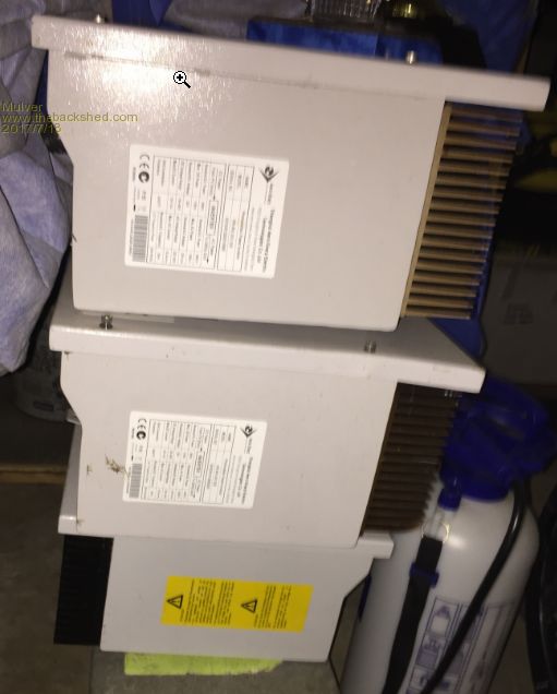
The beast!
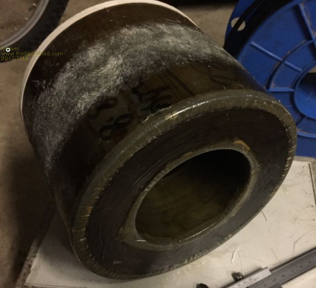
2x 3kw not yet tested, and a 1.5kw that faults out, its done a few hours so will probably be gutted.
My winding guide.
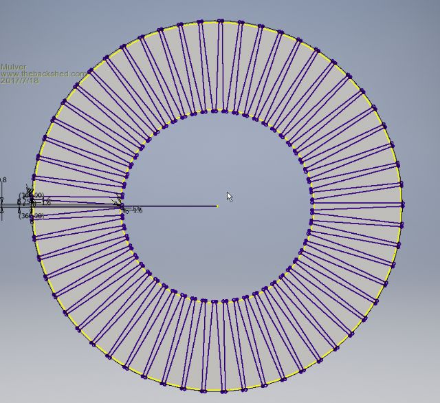
|
| |
Madness

Guru

Joined: 08/10/2011
Location: AustraliaPosts: 2498 |
| Posted: 01:51pm 18 Jul 2017 |
 Copy link to clipboard Copy link to clipboard |
 Print this post |
|
That is where I was a year ago, I stripped out 6 3KW Aerosharps as soon as I got them and then pieced one back together. It works fine but I am using a 5KW Zeversolar now mainly because I have a 5 KW solar array to connect to it.
Now I have 2 working home brew Inverters, one with a double core which runs the house and a single core as a backup.Edited by Madness 2017-07-19
There are only 10 types of people in the world: those who understand binary, and those who don't. |
| |
Mulver
Senior Member

Joined: 27/02/2017
Location: AustraliaPosts: 160 |
| Posted: 06:06pm 18 Jul 2017 |
 Copy link to clipboard Copy link to clipboard |
 Print this post |
|
I'm now even more excited with oz's controlled grid tie back charging, wont need to buy a dedicated charger as i see it. More money for panels!! |
| |
Madness

Guru

Joined: 08/10/2011
Location: AustraliaPosts: 2498 |
| Posted: 07:40pm 18 Jul 2017 |
 Copy link to clipboard Copy link to clipboard |
 Print this post |
|
There is Oztules DIY DC charge controller also, I have yet to do that, works much the same as the GTI control using 30V MPP panels in strings of 2 for a 48V battery and a bank of MOSFETs driven the same way by the PWM from the controller.
No reason you can't have both, I think the GTI is most efficient while powering AC loads directly and the dc to dc would be more efficient for charging. Having both gives you the best of both worlds. You can save 1 or 2 grand on charge controllers and save that and more on an inverter leaves you enough money to buy a truck load of second-hand panels.Edited by Madness 2017-07-20
There are only 10 types of people in the world: those who understand binary, and those who don't. |
| |
Warpspeed
Guru

Joined: 09/08/2007
Location: AustraliaPosts: 4406 |
| Posted: 12:10am 19 Jul 2017 |
 Copy link to clipboard Copy link to clipboard |
 Print this post |
|
Mulver, the 2.25 volts per turn value is not set in stone, you can design to have fewer volts per turn, and perhaps gain some significant advantage in doing so.
The first thing to realize is that all commercial transformers are designed to be sold for a profit. The transformer designer tries very hard to use the smallest amount of iron and copper to create a transformer that is pushing the safe limits of core saturation and temperature rise.
A professional transformer designer might select the smallest core, and the fewest turns of the thinnest wire he can possibly get away with. That will produce a small low cost transformer that runs hot, possibly hums, and draws a significant no load current. It will also usually create a massive turn on inrush surge current when it is first switched on.
We are doing this for ourselves, not trying to push the absolute limits of cheapness minimum size, and nastiness.
The trade offs are, fewer volts per turn will reduce the flux density in the core.
This has several advantages including much lower idling power which is very important for an inverter application. This is not a linear relationship, typically reducing the volts per turn by half might reduce the no load current to one sixth. So a little bit makes a very big improvement.
Fewer volts per turn will make for a more silent transformer, and it will reduce the turn on surge current problem that can sometimes lead to occasional inverter "blow ups".
The disadvantages are that a higher turns count increases the wire length that also increases the winding resistance, and hence heat generation. That is only a problem at sustained flat out maximum power, which few inverters ever see in practice.
Commercial mains connected transformers often run absolutely flat out to supply a fixed load continuously, but an inverter application rarely needs to do that.
A second disadvantage of a higher turns count is voltage regulation. More turns with higher resistance will produce a greater voltage drop under full load. That can sometimes be a problem with a conventional mains connected transformer, but an inverter usually has voltage feedback to compensate for changes in battery voltage, so it can also compensate for a slight reduction in transformer regulation.
Just because the Aerosharp cores originally used a fairly high flux density that works out to 2.25 volts per turn (for two stacked cores) there may be advantages to reducing that figure in a fresh new home brew inverter design, provided there is sufficient room to fit any extra turns on the core.
Even dropping to 2.0 volts per turn will be an advantage if you can do it.
Your inverter will probably spend most of its time running at 10% load or less, particularly at night. And see very occasional flat out peaks for only brief intervals. So designing for greater low load efficiency will pay dividends even if absolute flat out operation produces a bit more heat input because of higher dc resistance in the windings from the extra turns.
Cheers, Tony. |
| |
Mulver
Senior Member

Joined: 27/02/2017
Location: AustraliaPosts: 160 |
| Posted: 02:18am 19 Jul 2017 |
 Copy link to clipboard Copy link to clipboard |
 Print this post |
|
Thanks Tony! I've read and re read and understand "most" of what your saying. Really appreciate it!
I believe I'll have plenty of space.
So say I wind a 130 turn secondary, I plan to run at 230v so that's 1.77v per turn.
This would put my primary at 17 turns for 30v or should I still keep this down around the 15 turns ?
Or am I best to wind the secondary and test to find the best number of primary turns ? |
| |
Warpspeed
Guru

Joined: 09/08/2007
Location: AustraliaPosts: 4406 |
| Posted: 10:46am 19 Jul 2017 |
 Copy link to clipboard Copy link to clipboard |
 Print this post |
|
Probably the best practical approach is to just wind the secondary on first in one full complete layer, not being too concerned about the exact final turns count.
If it ends up having three turns less, or five turns more, its not a big deal.
Suppose it does end up at exactly 130 turns as you anticipated, that would be 1.77v per turn for 230v output. That would be excellent.
Once that is done, the next thing to think about would be the primary turns.
We design that for the minimum expected battery voltage, which might be 30v in this example. A lot depends on the battery type, and how far you wish to punish it.
The absolute maximum peak voltage the primary can ever see from 30v dc input, will be when the PWM value tops out at 100%, but the rms value will only be 70.71% of that, perhaps 21.2 volts rms.
So the primary will require 21.2 volts divided by 1.77 volts per turn, or 11.97 turns.
Twelve turns might be about right, although there will be unavoidable voltage drops within the system at full flat power that will mean 230v output is not achievable with only 30v input, but only at full load.
But that is asking rather a lot at absolute minimum battery voltage. Twelve turns would be about right over the normal expected operating range and should work fine. Edited by Warpspeed 2017-07-20
Cheers, Tony. |
| |
oztules

Guru

Joined: 26/07/2007
Location: AustraliaPosts: 1686 |
| Posted: 12:08pm 19 Jul 2017 |
 Copy link to clipboard Copy link to clipboard |
 Print this post |
|
As Warp says, wind your preferred secondary with your 130 turns.
For a 48v system, your aiming for about 28vrms primary.... so you can run the secondary on the 240vac ( with ballast for start up ) and see how many turns will be required for that.
The power jack boards can handle a wider voltage and so are normally wired for a 30-32v primary, but the 8010 has a less dynamic pwm, and 28v seems right to get high power put of it.
Yes it is exciting watching it come together. Once the tranny is done, it is all easier.
.......oztules
Village idiot...or... just another hack out of his depth |
| |
Mulver
Senior Member

Joined: 27/02/2017
Location: AustraliaPosts: 160 |
| Posted: 01:14am 20 Jul 2017 |
 Copy link to clipboard Copy link to clipboard |
 Print this post |
|
Thanks guys! Time to start winding, Ill get the first one on and take some readings. Just need some free time!
|
| |
Mulver
Senior Member

Joined: 27/02/2017
Location: AustraliaPosts: 160 |
| Posted: 02:25am 22 Jul 2017 |
 Copy link to clipboard Copy link to clipboard |
 Print this post |
|
I managed to get some time and wound the first layer secondary 130 turns.
Then wound on a test primary then powered up the secondary with a variac below are my results.
13 turns 230v = 22.3v 240v = 23.2v 250v = 24.3v
14 turns 230v = 24.1v 240v = 25.1v 250v = 26.2v
15 turns 230v = 25.8v 240v = 26.9v 250v = 28.0v
16 turns 230v = 27.4v 240v = 28.7v 250v = 29.9v
I tested the current on the 240v when powering the toroid and all I could get was 1.2 milliamperes. Is this right? My meters are not great and my good current meter is flat.
Next a coat of epoxy and keep winding. LOL] Edited by Mulver 2017-07-23 |
| |
oztules

Guru

Joined: 26/07/2007
Location: AustraliaPosts: 1686 |
| Posted: 12:01pm 22 Jul 2017 |
 Copy link to clipboard Copy link to clipboard |
 Print this post |
|
You have about 16 turns to do on the primary from the looks of it.
You are mile and miles away from saturation, it is really a 290v transformer, so at 230 it will be just ticking over. As warp has advised, your current should be small... not sure just how small, but 1.2ma seems low. There won't even be any hum I would think.
........oztules
Village idiot...or... just another hack out of his depth |
| |
Mulver
Senior Member

Joined: 27/02/2017
Location: AustraliaPosts: 160 |
| Posted: 02:02pm 22 Jul 2017 |
 Copy link to clipboard Copy link to clipboard |
 Print this post |
|
Awesome thanks! Yeh it was dead silent, no hum at all.
Also I plan on using Clockmans boards with the 8010. |
| |
Warpspeed
Guru

Joined: 09/08/2007
Location: AustraliaPosts: 4406 |
| Posted: 02:24pm 22 Jul 2017 |
 Copy link to clipboard Copy link to clipboard |
 Print this post |
|
Just for fun I connected up a 1.5Kw Inspire grid tie inverter transformer to my variac. This transformer has a 130 volt primary winding and a 230 volt secondary winding, with 130 and 230 turns.
At 0.9v/turn (207v) I measured 64mA magnetizing current.
At 1.0v/turn (230v) it was 73mA. Thats about 16.8VA which sounds about right.
As my variac only goes up to whatever the incoming mains voltage is, I made some fairly quick and dirty measurements using the 130 volt winding.
0.7 volts/turn (91v) 36mA
0.8 volts/turn (104v) 42mA
0.9 volts/turn (117v) 52mA
1.0 volts/turn (130v) 65mA
1.1 volts/turn (143v) 181mA
1.2 volts/turn (156v) 1.98amps wow !
Most commercial transformers in this size typically are designed to run about 1.0 to 1.1 volts per turn and its really pushing the limit.
If we design our inverter for that same flux level of 1.0 volts per turn, we could be looking at a no load idling power of something like 17 watts just due to the transformer no load magnetizing current. That would be about the best we could probably hope for.
If we added ten percent more turns to get us down to 0.9v per turn, (using the figures I measured on the 130 volt winding) the magnetizing current falls from 65mA to 52mA a drop of twenty percent.
If we add twenty percent more turns down to 0.8v per turn, the magnetizing current falls from 65mA to 42mA a drop by roughly one third.
The lower we go, the bigger the prospective improvement in inverter idling power.
Cheers, Tony. |
| |
Mulver
Senior Member

Joined: 27/02/2017
Location: AustraliaPosts: 160 |
| Posted: 09:43pm 24 Jul 2017 |
 Copy link to clipboard Copy link to clipboard |
 Print this post |
|
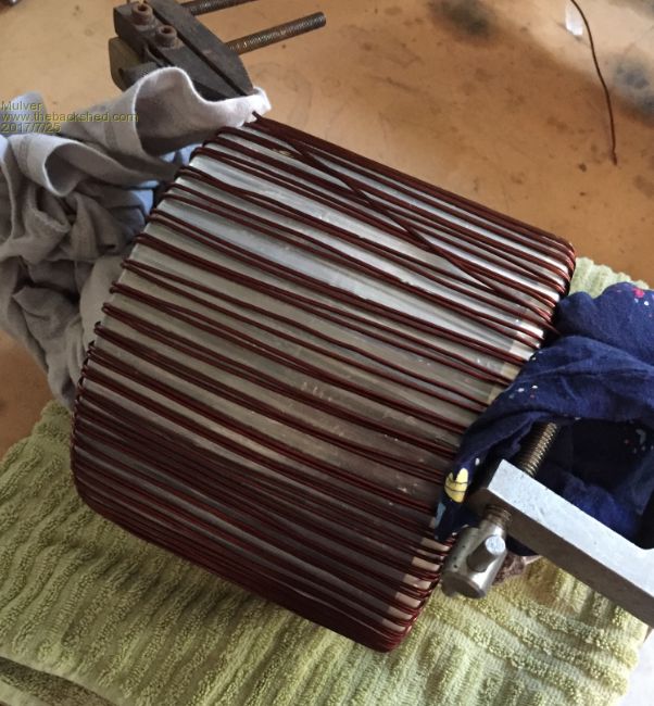
2 layers of Mylar, Heat gun works a treat for removing crinkles in second hand mylar after winding it on.
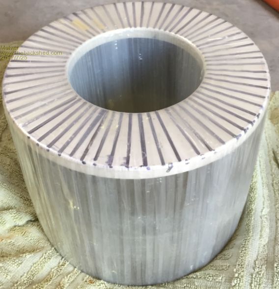
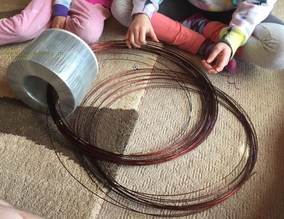
My winding helpers, yes that's how i wound it on, a little tricky! You must back bend to get the wire laying on the toroid. It did wear my hands out after completing 130turns
Finished first layer of 130 turns, starting to epoxy the winding.
Oztules/Clockman its stated that you use chalk powder to thicken the epoxy.
Are we talking ground up white blackboard chalk? or string line chalk? or something else?
Cheers
|
| |
Clockmanfr

Guru

Joined: 23/10/2015
Location: FrancePosts: 429 |
| Posted: 10:16pm 24 Jul 2017 |
 Copy link to clipboard Copy link to clipboard |
 Print this post |
|
Hi Mulver,
Fiberglass folk use a very fine chalk powder. Mix it with the resin first.
Its used as a thickening agent by weight proportions 20 grams of resin, max of 20 grams of chalk.
The chalk stops the resin from overheating and cracking if used in moulds, but it takes longer for the resin to set.
Everything is possible, just give me time.
3 HughP's 3.7m Wind T's (14 years). 5kW PV on 3 Trackers, (10 yrs). 21kW PV AC coupled SH GTI's. OzInverter created Grid. 1300ah 48v. |
| |
Madness

Guru

Joined: 08/10/2011
Location: AustraliaPosts: 2498 |
| Posted: 10:41pm 24 Jul 2017 |
 Copy link to clipboard Copy link to clipboard |
 Print this post |
|
I thought the epoxy on the windings was to be as thin as possible or I have gone completely mad?
There are only 10 types of people in the world: those who understand binary, and those who don't. |
| |
oztules

Guru

Joined: 26/07/2007
Location: AustraliaPosts: 1686 |
| Posted: 12:32am 25 Jul 2017 |
 Copy link to clipboard Copy link to clipboard |
 Print this post |
|
I just use west systems epoxy neat... no thickener.
I want max adhesion to the lacquer/wire to fill the tiny micro holes I cant see... but assume are there somewhere because of the horrible time I have given to the wire. The enamel is good, but I don't know how good.
However, the thickener may not be a bad idea if you are trying to shape your creation.
It looks good so far.... and I am in awe at your training ability... two little helpers that actually help.... thats abnormally good.
.........oztules
Village idiot...or... just another hack out of his depth |
| |
| |
Page 1 of 3   |

