
|

|
Forum Index : Electronics : VFD Running off Inverter
| Page 1 of 3 |
|||||
| Author | Message | ||||
Madness Guru Joined: 08/10/2011 Location: AustraliaPosts: 2498 |
Has anybody had any experience using a Variable Frequency Drive off of a off grid Inverter? I am looking at buying one of these to run a combination wood saw table/planer/spindle moulder. The machine is 3 phase and has 3 motors so just changing the motor is not so easy. For this machine, I am not concerned about variable speed but the inbuilt braking function of the VFD would be nice. There are only 10 types of people in the world: those who understand binary, and those who don't. |
||||
oztules Guru Joined: 26/07/2007 Location: AustraliaPosts: 1686 |
no problems at all. The desalinator out on one of the islands runs one of these things at 1.5kw all day, as well as the house loads ( inc 2.5kw hot water )... so no problems anticipated. For full power remember this is only 240v... so hopefully the motors are naturally star, and can be converted to delta. I have had a few that were naturally delta.... so needed coil surgery to get the voltage down from 415v to 240v Mod sine, or pure sine will all do it, as it rectifies the power as soon as it comes into the VFD... so waveform is not critical. ..........oztules Village idiot...or... just another hack out of his depth |
||||
Madness Guru Joined: 08/10/2011 Location: AustraliaPosts: 2498 |
Thanks Oz, I will have to have a closer look at the woodworking machine before buying it. It is made in Belgium and is about 30 years old, if the motors are hard wired as delta I won't be trying to modify it. There are only 10 types of people in the world: those who understand binary, and those who don't. |
||||
Bryan1 Guru Joined: 22/02/2006 Location: AustraliaPosts: 1344 |
Hi Madness, I've been running VFD's in my shed for years off that 3Kw sinewave inverter I bought in '05. Both my lathes and my bridgeport mill are powered by them and oneday I'll bring my surface grinder back to life as I do have a 1/2hp 2 pole 3 phase motor and new VFD put aside for it. Now with the VFD one can program them so a 2hp motor thinks it's a 3hp motor by changing a few parameters. Also one can set the Hz to 100 so double the motor speed and by doing a simple 3 wire circuit one can have a 5K pot for speed control, On/Off, forward/reverse and if fitted to the VFD Jogging. As far as current when I use my big lathe doing a 3mm cut the current draw shown on the VFD is about 7 amps ( on a 2hp motor). As far as voltage drop on my 735AH traction battery 0.1 volt drop under load. Cheers Bryan |
||||
Madness Guru Joined: 08/10/2011 Location: AustraliaPosts: 2498 |
Hi Bryan, Just got the machine home yesterday that I plan to use the VFD on, it has 3 4 hp motors. There is a selector switch for each function and one of the motors has 2 speed selections. What I am hoping is that I can use one VFD to run each motor via the selector switch. The 2 speed motor runs a spindle at either 3000 or 6000 RPM via a belt drive. I have purchased the VFD in the link on my original post but it has not arrived yet. The VFD is rated for up to 5HP and the seller assures me it will do that continuously, not that it is possible to feed wood into it nonstop. Nor would it be working at full load most of the time, the machine was built in 1985 and is designed for commercial use so I suspect the motors would be overrated anyway. So my plan is to see if the VFD can run each motor via the selector with the same setting for each one, obviously, it needs to be shut down before changing the selector. Here is a wiring diagram I found. 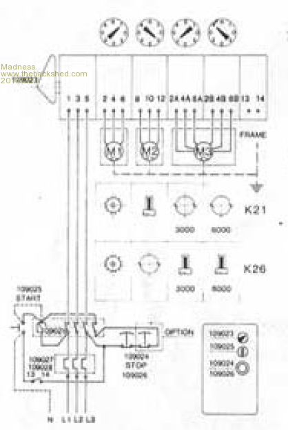 There are only 10 types of people in the world: those who understand binary, and those who don't. |
||||
oztules Guru Joined: 26/07/2007 Location: AustraliaPosts: 1686 |
"obviously, it needs to be shut down" Yes ONLY the vfd should turn on or off any motor... you must not turn on the VFD and then turn on a switch to any mpotor/s This means that bypassing any on/off switching is very desirable so you cannot switch it of by any other means than the VFD itself. It may be possible to run the main motor and then turn on and off a secondary motor of smaller size, as the main motor will help the start current.. but still not at all desirable. Ideally the VFD should be in control of all aspects of start/ stop/running. It you need emergency stop, then interrupt the single phase inputs, not the three phase outputs. In short the vfd should be HARD wired directly to the motor/s and switched on and off by the vfd only. It will probably suffer a single phase input shut off.... not recommended but have not seen it cause any problems ever.... and I do it a lot more than I should. If you want multiple switching, then multiple vfd may be the best way to go in the end..... may get tedious doing full shut down for each motor change. DO use the ramp up acceleration liberally. Thats as I have learnt to live with them anyway. ...........oztules Village idiot...or... just another hack out of his depth |
||||
Madness Guru Joined: 08/10/2011 Location: AustraliaPosts: 2498 |
Hi Oz, Having to shut down between functions would not be a big deal, I am thinking if I made a cover to go over the selector switch that triggered the emergency stop when opened it will make it impossible to switch functions while running. The existing start-stop switches can be rewired to operate the VFD remote connectors. There are only 10 types of people in the world: those who understand binary, and those who don't. |
||||
| Warpspeed Guru Joined: 09/08/2007 Location: AustraliaPosts: 4406 |
[quote]In short the vfd should be HARD wired directly to the motor/s and switched on and off by the vfd only. It will probably suffer a single phase input shut off.... not recommended but have not seen it cause any problems ever.... and I do it a lot more than I should.[/quote] Yes, this is very important. Most modern VFDs detect motor problems, including no motor connected, and will shut down with a fault code. The way I have seen this dome is to use a large rotary multi pole cam switch, to select the required motor. Place this switch under a hinged transparent cover, where the cover has a "cover closed" switch that enables main power. It can be connected to the emergency stop input to the VFD. No power to the motor if the cover is open. But you need to open the cover to change over motors. Its pretty fool proof even if you are very busy, get distracted, or are sometimes a bit absent minded. Cheers, Tony. |
||||
Madness Guru Joined: 08/10/2011 Location: AustraliaPosts: 2498 |
Hi Tony, Yes, that is exactly what I had in mind, the machine already has the rotary switch. I have some 5 mm clear polycarbonate sheet offcuts to make the cover and fit a sealed microswitch so that it does not get wood dust in it. The VFD has provision for remote switches and speed control. So I can wire the stop buttons located around the machine to the VFD. For ramp up time, I thinking 3 seconds would be a practical amount of time. There are only 10 types of people in the world: those who understand binary, and those who don't. |
||||
| Warpspeed Guru Joined: 09/08/2007 Location: AustraliaPosts: 4406 |
Ramp up time mainly has to do with motor inrush current, and any inertia associated with the motor load. Woodworking machinery should accelerate pretty fast at startup, and three seconds sounds about right. Sounds like you have it all pretty much figured out. Microswitch sounds good, or you could use a magnet and a reed relay contact. Cheers, Tony. |
||||
| yahoo2 Guru Joined: 05/04/2011 Location: AustraliaPosts: 1166 |
I use vfd units from automation direct and have had no problems in any off grid workshops yet. https://www.youtube.com/watch?v=nFPX1pW3Sl8 quick video of Jeff showing conversions on a drill press and lathe for anyone interested in that sort of thing. I'm confused, no wait... maybe I'm not... |
||||
| Warpspeed Guru Joined: 09/08/2007 Location: AustraliaPosts: 4406 |
Its definitely a handy thing, especially for woodworking, but it has its limitations for heavy duty metal cutting drills and lathes. The basic problem is that, sure you can slow it right down, but you don't get the torque multiplication that belts or gears give when set to a much greater mechanical reduction ratio. So for something like a large metal cutting lathe run at very low speed (with a gearbox) a massive torque multiplication comes naturally with the slow speed. A slow speed set on a VFD means you cannot use a deep cut, the motor will just stall. Same with large hole saws in a drill press. If you are cutting a three inch diameter hole through half inch steel plate at 20 rpm with coolant, you need torque. And a VFD simply will not give it to you. Should work great for large diameter hole saws in soft material like thin plywood or plastic, so you don't burn up either the job or the hole saw. So it really depends what you want to use it for. Cheers, Tony. |
||||
Madness Guru Joined: 08/10/2011 Location: AustraliaPosts: 2498 |
Still waiting for the VFD to arrive via Fastway was sent Wednesday tracking says still between Melbourne and Sunshine Coast. From past experience, Slowway might be a better name for them. 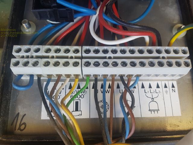 All 3 motors are setup differently, first motor on the planer was dead simple to change to Delta. 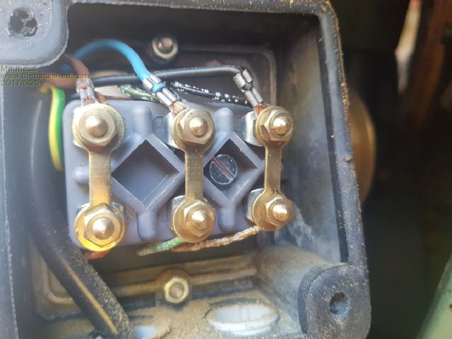 Next the saw motor took slightly longer to figure out, it simply has 6 wires coming out with 3 joined together, I separated them and just need to rewire them correctly for delta. 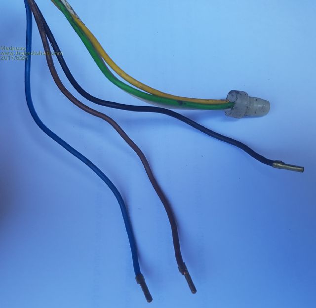 Brown - Yellow = 1 winding Black - Green = 2nd winding Blue - White = 3rd winding. The 2 speed motor for the spindle moulder is a bit more involved, from what I can figure out it is a Dahlander configuration like this. 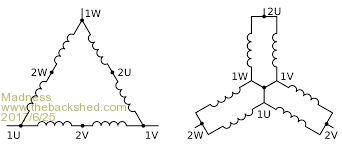 There is no simple external way to change it to 240V Delta from what I have found. It needs to have each of the Delta windings legs changed from series to parallel, as per this diagram. 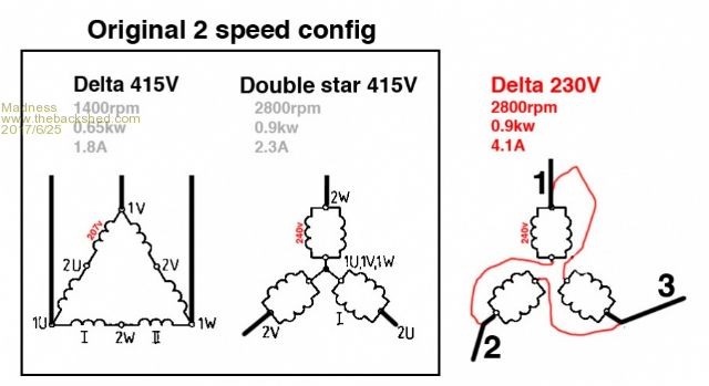 These are the connections of my motor 6.8 ohms on each winding, it seems odd that the W2 and U2 seem to be swapped around. 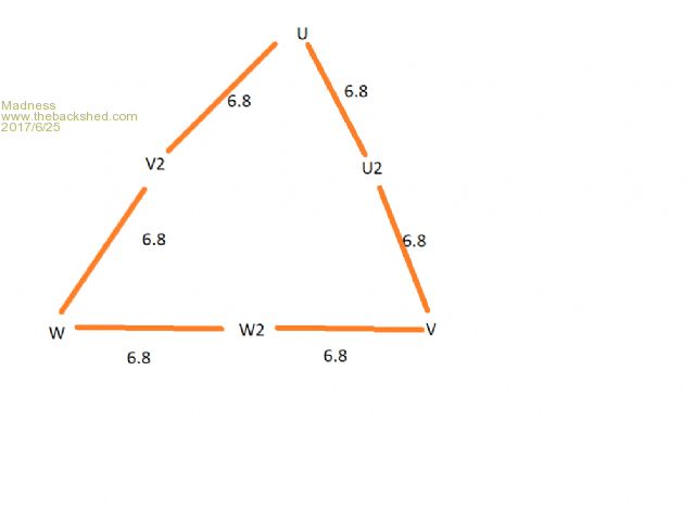 This is the resistances I get between terminals U - U2 6.8 U - V2 6.8 U - W2 12.2 V - V2 12.2 V - W2 6.8 V - U2 6.8 W - W2 6.8 W - U2 12.2 W - V2 6.8 Next step is to get the motor out and disassembled to see if I can perform the required surgery on it. Changing it to 240 Delta will eliminate it's 2 speed capability which is no problem as the VFD will provide variable speed. There are only 10 types of people in the world: those who understand binary, and those who don't. |
||||
| Warpspeed Guru Joined: 09/08/2007 Location: AustraliaPosts: 4406 |
Most VFDs you can set the required nominal output voltage, it does not need to be set to 415v, although that is very likely the VFD default setting if its an Aussie delivered unit. Whatever voltage the motors were used at originally, you could possibly return to that and tweak the VFD appropriately. That may be a giant step backwards, but just thought I would mention it as something to consider. Cheers, Tony. |
||||
oztules Guru Joined: 26/07/2007 Location: AustraliaPosts: 1686 |
I'm guessing 6 wires on the left of the first picture are the ones in question.... it looks simple to just connect the wires coming from the motor at this junction, the wires coming from the dual switch are confusing the issue. so just using the wires coming from the bottom of the pic, and throwing away the ones coming from the top. ie if you connect at the white multi terminal block say 1W to 2V and 1V to 2U and 1U to 2W... then the 3ph from the vfd to 2W,2U and2V, you should have what you want right there. Warp, I suspect his is 240v 1phase in 240v 3 ph out. I would use 5 seconds start up at least. ..........oztules Village idiot...or... just another hack out of his depth |
||||
| Warpspeed Guru Joined: 09/08/2007 Location: AustraliaPosts: 4406 |
240v three phase out is 415 phase to phase. It probably cannot reach that, but it might get to 230v three phase out with 240v nominal single phase input. Input voltage goes to a rectifier that generates +340v dc and -340v dc (the peak mains voltages reached with 240v single phase input). That is PWM'd to produce three nominal outputs of probably around 230v rms. Cheers, Tony. |
||||
oztules Guru Joined: 26/07/2007 Location: AustraliaPosts: 1686 |
No, the ones I have worked on are not like that. I spent $700 on a bigger unit, and proceeded to blow it up in the first 5 mins. It used a big intergrated H bridge ( 1200v 40 amps ) and incorporated the bridge as well in the same package.... learnt a lot from that  I could only make 1.414X the input AC rms voltage... it's package was this thing 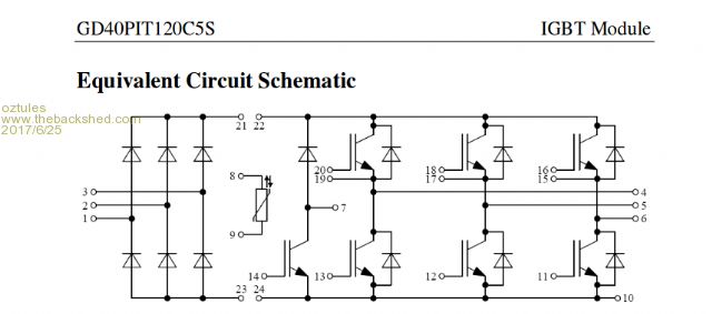 So it is only the 340vdc not + and - rail.... thus only 240v 3 phase was possible. My 240v 3 phase is 240v phase to phase. There is no neutral available unless you use a transformer..... sorry for any mix up, but I thought thats how we would use the terminology. ........oztules Village idiot...or... just another hack out of his depth |
||||
| Warpspeed Guru Joined: 09/08/2007 Location: AustraliaPosts: 4406 |
I understood this was going to be run off 240v single phase from an off grid system ? Now you are talking about a high power VFD driven from a three phase supply. Anything more than about 2Hp will require a three phase input. If all you have is a single phase supply coming from an inverter, the way I suggested is the ONLY way it can possibly work. My own VFDs I use at home all run from 415v three phase without a neutral exactly as you suggest. I used to work for a company as a field engineer repairing VFDs, so I do know something of how they work. Cheers, Tony. |
||||
Madness Guru Joined: 08/10/2011 Location: AustraliaPosts: 2498 |
I am going to be running from a single phase 240V supply, all the information I have seen on this type of VFD say you must change the motors to 220/240V delta configuration. To run at the 380/415 requires 3 phase supply of the same voltage or a step up transformer. All 3 motors in this machine are rated at 2.2KW, the VFD I have coming is 3.7KW. The seller has assured me it will handle it's full rated power continuously. Oz I have been trawling through the net and see a lot of talk of lathes with the same type of 2 speed motor, I have read that you can run it without rewiring but with 29 hz as the base speed. However, this results in reduced HP. But you can believe everything you read on the Internet, so I welcome any input. There are only 10 types of people in the world: those who understand binary, and those who don't. |
||||
| Warpspeed Guru Joined: 09/08/2007 Location: AustraliaPosts: 4406 |
Ah, yes now I see what you are doing. That will certainly work. Its a bit unusual because it requires non standard voltage motors. I have seen very small drives run the way I suggested to use standard motors but only up to about 2HP because the single phase current becomes too high for a normal power outlet above that. Cheers, Tony. |
||||
| Page 1 of 3 |
|||||