
|

|
Forum Index : Electronics : BigOzInverter
| Page 1 of 3 |
|||||
| Author | Message | ||||
| Clockmanfr Guru Joined: 23/10/2015 Location: FrancePosts: 429 |
Hi, Some of you may have already seen some of my OzInverter posts, the OzInverter Book and the OzInverter PCB’s, (OzControl, OzCooling, and my Big Power Board). Here I will post differences that occur with this BigOzInverter Build. My 6kW OzInverters work flawlessly and do everything I want of them. Yes, they are robust, simple and very cost effective. However, next year we will be having guests here to stay, and energy control and its use, is a moot point with most modern normal folk. The BigOzInverter build will push the boundaries a bit. So I am looking at a constant 8kW to 10kW output with large surges. My present battery bank is 48v 1300ah, so most of the time I have GTI’s, (Solar Grid Tie Inverters) putting their power into my OzInverter created Mini Grid. But, there will be times in the future where the BigOzInverter will be required to step in. I talked about my BigOzInverter design here…… http://www.anotherpower.com/board/index.php/topic,1117.0.html?PHPSESSID=h7jd5l4edljl6k4ls18pgfj4i1 So I have a 38kg core, at 230mm OD, 100mm centre hole and 140mm thick/high. 80 turns of 6 off, 1.8mm diameter secondary and 10 turns of 1 off, 75mm/2 for the primary. The 38kg core is heavy and awkward to lift and turn without damaging the enamelling on the windings. The first photo shows an amended winding table with sufficient space to safely get my fingers under the core and cleanly lift. There are 6 rubber mats cut out, each at 1.1mm thick taped to the table. This works well as the rubber gives and spreads the weight without collapsing or being to stiff. 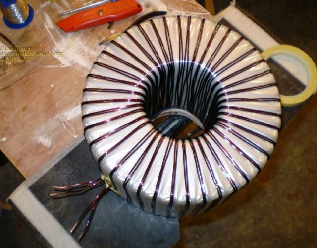 Differences with Testing the Secondary windings. My normal 25w 230vac test bulb that I use on the 6kW OzInverters was just too small a wattage for the torroid to step up to full 230vac on each winding, and my workshop 20 amp MCB would trip out. However, replacing the 25w with a 100w 230vac test bulb works fine, as the interim step for the each secondary taking a full 230vac. But be warned the 100w bulb will not illuminate, the toroid seems to want everything. These first 2 secondary windings are fine and each gives the same Induced voltage readings. The Photo shows the 100w bulb that is now bypassed with that insulated croc clip, so the toroid first secondary winding is taking the full 238vac Mains, and inducing 238vac in the second secondary winding. And Yes, I will tidy up the windings before I resin coat them, but I always test first. 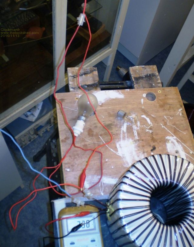 WARNING. Yes I should no better! 230vac is serious and will probably KILL you, so be very very careful. Check and double check. Everything is possible, just give me time. 3 HughP's 3.7m Wind T's (14 years). 5kW PV on 3 Trackers, (10 yrs). 21kW PV AC coupled SH GTI's. OzInverter created Grid. 1300ah 48v. |
||||
oztules Guru Joined: 26/07/2007 Location: AustraliaPosts: 1686 |
Yup... thats serious. ........oztules Village idiot...or... just another hack out of his depth |
||||
| Tinker Guru Joined: 07/11/2007 Location: AustraliaPosts: 1904 |
Clockman, if you can source a VARIAC (Variable voltage output transformer), this would eliminate the bulb you use for startup completely. Only a small one is required - mine only has a 0.5A capacity and works very well for the expected idle current of a dual stack core. You power the secondary initially from zero V AC and slowly wind the voltage knob up to your expected mains voltage. You can meter the AC voltage and current as you go. Since there is no inrush current you can connect a multimeter set to AC mA range for the current. Well worth while if you do some experimenting. But take care and REMEMBER, most VARIACS are Auto transformers and hence, the output winding has a direct connection to the input winding. You will get a shock if you are earthed and touch just one of the test wires. Klaus |
||||
| Clockmanfr Guru Joined: 23/10/2015 Location: FrancePosts: 429 |
Hi Tinker, Thanks for the tip re VARIAC, however as rare as rocking horse poo here, but your comments noted. Everything is possible, just give me time. 3 HughP's 3.7m Wind T's (14 years). 5kW PV on 3 Trackers, (10 yrs). 21kW PV AC coupled SH GTI's. OzInverter created Grid. 1300ah 48v. |
||||
| Clockmanfr Guru Joined: 23/10/2015 Location: FrancePosts: 429 |
Hi Oztules, Just some clarification required, regards my new 60 amp EMI Filter on the 230vac output from my BigOzInverter. I have been happy with the 4 unit arrangement and this works well on the 6kW OzInverter. 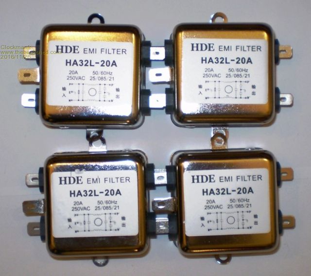 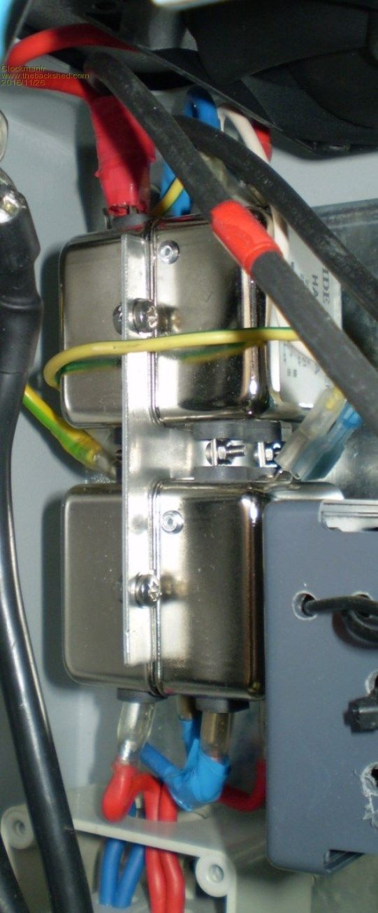 Here is my Block diagram regards the design of the triple unit, 9off, and connection system. This okay? 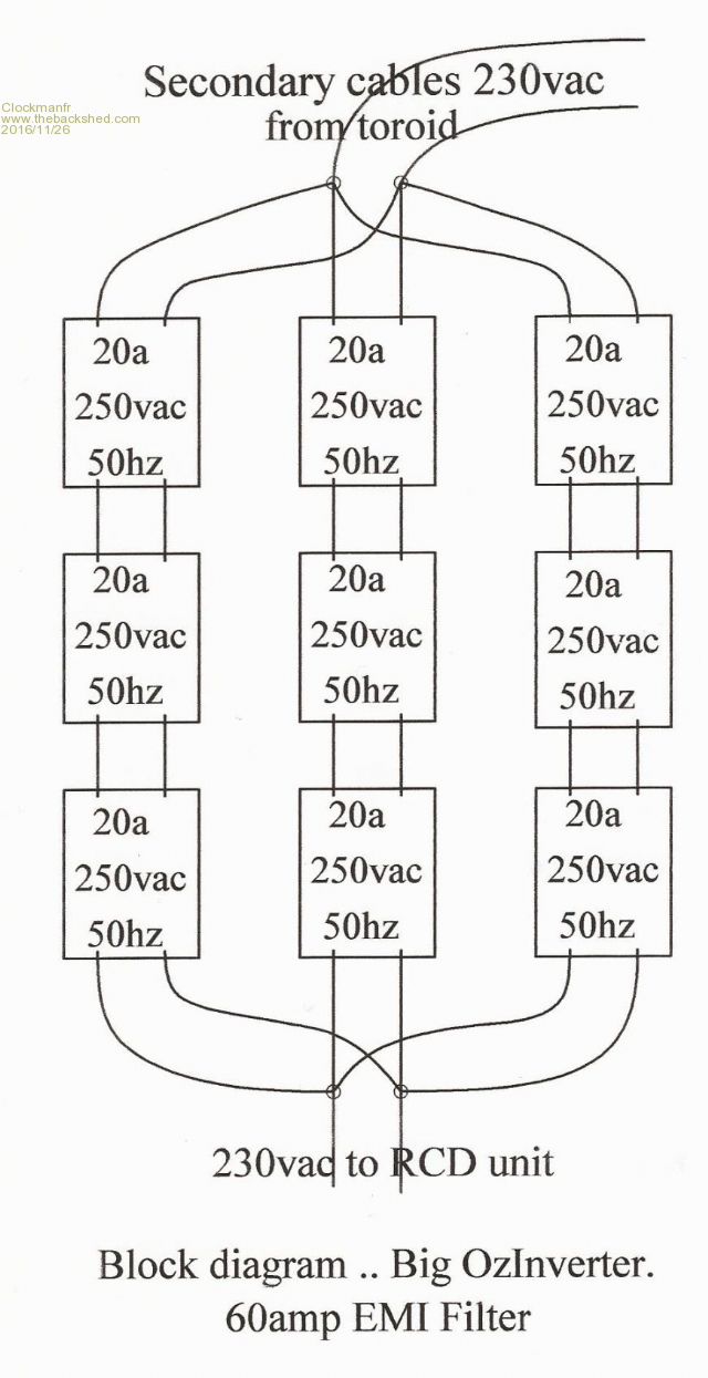 Everything is possible, just give me time. 3 HughP's 3.7m Wind T's (14 years). 5kW PV on 3 Trackers, (10 yrs). 21kW PV AC coupled SH GTI's. OzInverter created Grid. 1300ah 48v. |
||||
| Clockmanfr Guru Joined: 23/10/2015 Location: FrancePosts: 429 |
For clarification, here is my Block diagram for the 230vac side of the OzInverter. I will amend and add this into the OzInverter Book. 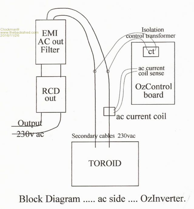 NOTE, those 20a 250vac 50Hz EMI Filter units are about $7 each, 9off for my big filter unit would be about $63, which is not to bad. Everything is possible, just give me time. 3 HughP's 3.7m Wind T's (14 years). 5kW PV on 3 Trackers, (10 yrs). 21kW PV AC coupled SH GTI's. OzInverter created Grid. 1300ah 48v. |
||||
oztules Guru Joined: 26/07/2007 Location: AustraliaPosts: 1686 |
Well that should filter out some noise. Front loader washing machines with older series wound motors need a filter on the output so as to run their spin cycles properly.... and yep, that would do it. ......oztules Village idiot...or... just another hack out of his depth |
||||
| Clockmanfr Guru Joined: 23/10/2015 Location: FrancePosts: 429 |
Thanks Oztules. Everything is possible, just give me time. 3 HughP's 3.7m Wind T's (14 years). 5kW PV on 3 Trackers, (10 yrs). 21kW PV AC coupled SH GTI's. OzInverter created Grid. 1300ah 48v. |
||||
| Clockmanfr Guru Joined: 23/10/2015 Location: FrancePosts: 429 |
The Ferrite core. On one of the two Primary cables from the Toroid. Brings the idle power loss right down, for a 6kW about 35watts. My Primary cable for this BigOzInverter is 70mm/2 and here I am using very flexible welding cable at 18mm/ 3/4inch diameter, wrapped around the 20mm x 40mm x 56mm long centre section of the ferrite core. 3 complete turns is ideal, 4 is a little better but not worth the extra hassle involved. Here I am using 2off these cores stuck together with super glue or resin…… .. http://www.ebay.co.uk/itm/370683164776?_trksid=p2057872.m2749.l2649&ssPageName=STRK%3AMEBIDX%3AIT http://www.ebay.co.uk/itm/370683164776?_trksid=p2057872.m2749.l2649&ssPageName=STRK%3AMEBIDX%3AIT 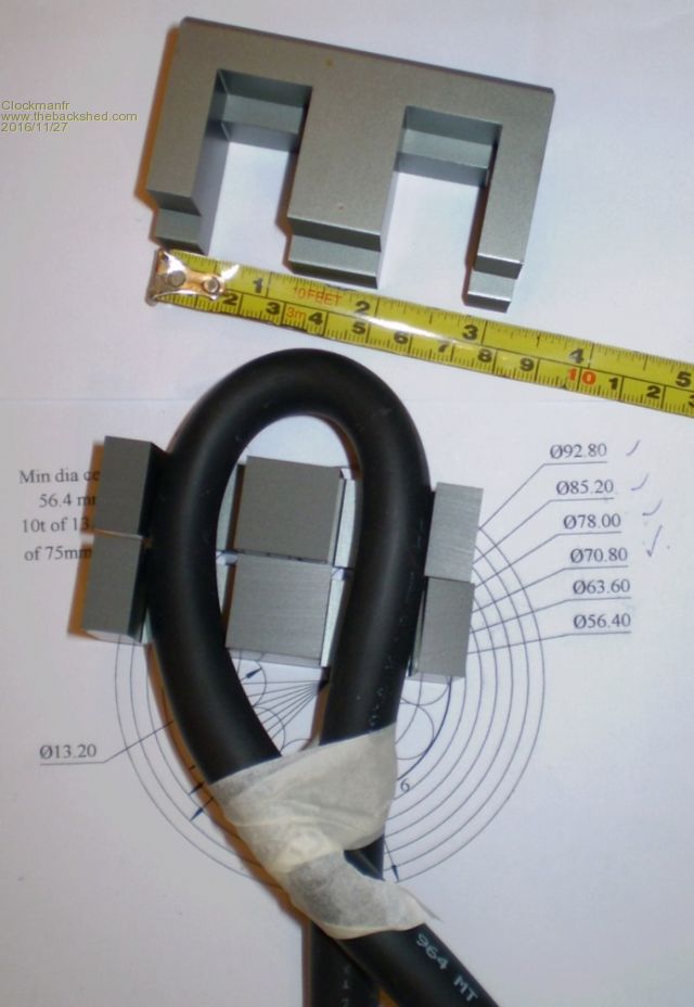 Everything is possible, just give me time. 3 HughP's 3.7m Wind T's (14 years). 5kW PV on 3 Trackers, (10 yrs). 21kW PV AC coupled SH GTI's. OzInverter created Grid. 1300ah 48v. |
||||
| mason Regular Member Joined: 07/11/2015 Location: CanadaPosts: 86 |
Hi Clockman, Just wondering if you have the unit together yet, I'm building a pj unit and my toroid cores are about the same size as yours maybe 1/2 inch taller. I did my first winding and I got 2.32v per windings so 112 will give 259.84v. Just wondering what your readings are when you have the unit up and running. Thanks |
||||
| Clockmanfr Guru Joined: 23/10/2015 Location: FrancePosts: 429 |
Hi Mason, As 'Oztules' remarked....(I keep all his words of wisdom, nearly 100,000 now). "We want the primary to be about 30 to 32v for the PJ style processors, and 28-30 for the 8010 chips for a nominal 48v system." So I have a 38kg/83lbs core, at 230mm/9inch OD, 100mm/4inch centre hole and 140mm/5 1/2inch thick/high. "Lemme see...... I make that as about 9100mmsq cross section... so ... and here I can only go rule of thumb....9000/2800=3.25 So I figure about 3.25 volts per turn. So the secondary will be about 73 turns, and the primary will be about 9 turns. How that would be worked out mathematically I can only postulate, but the in the real world measurements I have done, it would seem to indicate that roughly 2800mmsq of cross section at 50hz will yield about 1turn/volt.... so 9000mmsq would be about 3.25 volts/turn. If we wind for a few more volts than we want, our saturation is further away... so say 240 or 260v for a 220v system gives us leeway and lower magnetising current ... from there about 1:8 primary : secondary.. and we have a workable start point.... at least that how I would tackle it. ..... ' Oztules '" So going from my experiences with the 6kW Ozinverter .... the BigOzInverter will be 80 turns of 6 off, 1.8mm diameter secondary and 10 turns of 1 off, 75mm/2 for the primary, basically the magic 8 to 1 ratio. I am looking for a test 28v - 30v on the Primary when I put 230vac on the secondary. Interestingly my first PJ OzInverter windings gave me 28v on the primary, but as 'Oztules' said, "You will get better headroom at lower battery voltages", and yes I do. Yes, I will do readings and show them here, but this is a spare time job at present, well at present early mornings. Its very frosty -5c and the ground is hard to dig until the sun gets going after midday. Other considerations should be noted regards the core material. My core supplier company reckons that to much varnish getting into the 0.3mm thick 3% silicone Iron alloy laminations, has a considerable magnetic degradation of 15% with varnish, and 40% with epoxy. Everything is possible, just give me time. 3 HughP's 3.7m Wind T's (14 years). 5kW PV on 3 Trackers, (10 yrs). 21kW PV AC coupled SH GTI's. OzInverter created Grid. 1300ah 48v. |
||||
| Clockmanfr Guru Joined: 23/10/2015 Location: FrancePosts: 429 |
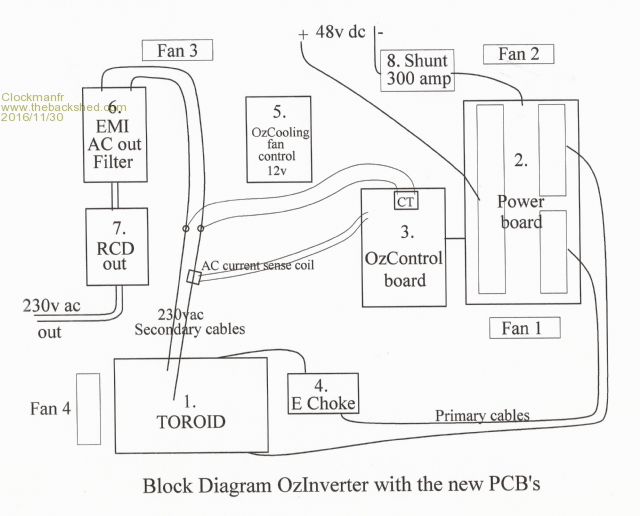 Everything is possible, just give me time. 3 HughP's 3.7m Wind T's (14 years). 5kW PV on 3 Trackers, (10 yrs). 21kW PV AC coupled SH GTI's. OzInverter created Grid. 1300ah 48v. |
||||
| mason Regular Member Joined: 07/11/2015 Location: CanadaPosts: 86 |
My calculations are way off, I'm getting 3.18v per turn, so I have way to many turns on my secondarys, wondering if you can reduce the number of primary turns? |
||||
| Clockmanfr Guru Joined: 23/10/2015 Location: FrancePosts: 429 |
At 3.18v per turn, then for a 240vac that would be 75 turns, however push it to 260vac, see 'Oztules' explanation my previous post, then its about 82 turns in the real World. Using the 8 to 1 ratio then the primary would be 10 turns, but depends on how good your cores are, so allow for 11 turn primary. Its a lot easier to remove than add. Just temp wrap a primary, any size of cable for the test, around your first secondary, apply 240vac to secondary using the step up test with the light bulb, put the meter on the primary and see what you get. You are looking for between 30v and 32v. Just running your present 112 turns secondary would be about 14 turns primary, but then that equates to running at 356vac, I am not sure about that. ? Perhaps 'Oztules' can clarify? Everything is possible, just give me time. 3 HughP's 3.7m Wind T's (14 years). 5kW PV on 3 Trackers, (10 yrs). 21kW PV AC coupled SH GTI's. OzInverter created Grid. 1300ah 48v. |
||||
| mason Regular Member Joined: 07/11/2015 Location: CanadaPosts: 86 |
Thanks Clockman, Have you did a test primary on yours? I thought it was 15 primary turns for PJ setup My core is 9"od x 5"id x 7" high # 200 from Alpa core. Yeah maybe Oztules can chime in on this Mason |
||||
oztules Guru Joined: 26/07/2007 Location: AustraliaPosts: 1686 |
Simple rules say 3.16v/turn... you found 3.18/// so close enough. If we wind for 260v then 260/3.16=83 turns for the secondary, probably 10 or 11 turns for the primary would be worth a try. ..........oztules Village idiot...or... just another hack out of his depth |
||||
| Clockmanfr Guru Joined: 23/10/2015 Location: FrancePosts: 429 |
Here you are Mason, 'Oztules' calculations work in the real World...... This is for the 8010 OzControl Board where we want 28v to 30v. Test.....234vac going in to the secondary windings 80 turns, and 29.4vac coming out of the 10 turn Primary. 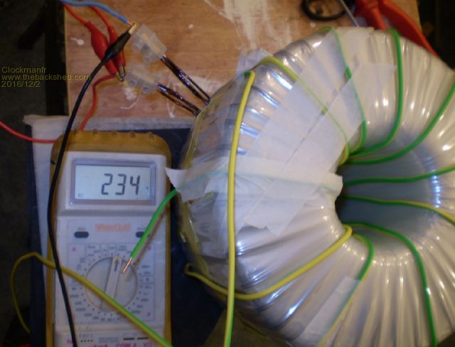 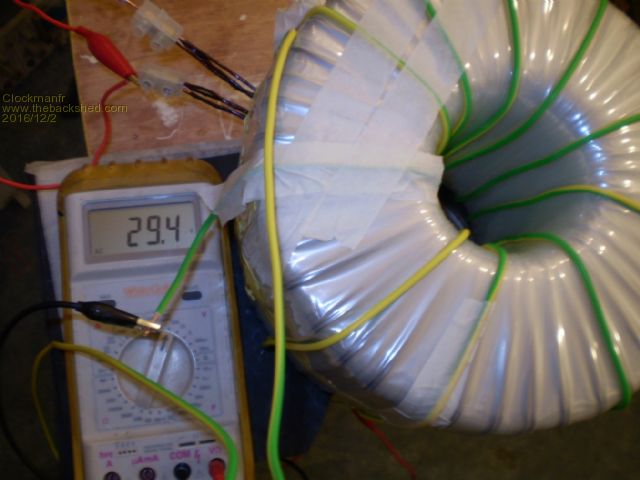 Oztules, I think Mason has got the calculations wrong and wound a 112 turn secondary's. He said above, 'secondary's', so I presume he has done a few.? Rather than remove excess turns and go to 83 turns. I think he wants to know if he can adjust the Primary turns to 14,with 112 turns? and will this higher number of turns on the secondary and primary cause any ramifications. ? Everything is possible, just give me time. 3 HughP's 3.7m Wind T's (14 years). 5kW PV on 3 Trackers, (10 yrs). 21kW PV AC coupled SH GTI's. OzInverter created Grid. 1300ah 48v. |
||||
oztules Guru Joined: 26/07/2007 Location: AustraliaPosts: 1686 |
In a word.... yes. It will have less magnetising current required, so less iron loss, but more copper loss. My experience is that the transformer spends most of it's time at low power... in the sub 500 watts range.... so the copper loss will be less important than the gains to be had with less idle current.... ie probably not a bad thing in the scheme of things. If he wanted to run hard a lot of the time, then it would be better to lower the copper loses, and live with the higher iron less. So for extended high power, get the secondary turns down to 83 ... and for normal off grid, then you will do fine with your 112 and 14.... you may then consider an extra layer of secondary, and get the copper loss back down as well... then best of both worlds. .........oztules Village idiot...or... just another hack out of his depth |
||||
| mason Regular Member Joined: 07/11/2015 Location: CanadaPosts: 86 |
Thanks Guys, I only have two layers done so I'll cut back to 82 turns leave the left over ones there and use them as my 3rd layer. Mason |
||||
| Clockmanfr Guru Joined: 23/10/2015 Location: FrancePosts: 429 |
Thank You 'Oztules', another fine understandable explanation. Will add it to your 'words of wisdom'. Everything is possible, just give me time. 3 HughP's 3.7m Wind T's (14 years). 5kW PV on 3 Trackers, (10 yrs). 21kW PV AC coupled SH GTI's. OzInverter created Grid. 1300ah 48v. |
||||
| Page 1 of 3 |
|||||