| Author |
Message |
domwild
Guru

Joined: 16/12/2005
Location: AustraliaPosts: 873 |
| Posted: 05:54pm 20 Oct 2016 |
 Copy link to clipboard Copy link to clipboard |
 Print this post |
|
Hi,
So I can make an informed decision with a licensed electrician I'd like to ask a few questions. I have two choices of switching on a pump (2 HP, 15A running), a solenoid for filling the tank from another source and level sensing to stop overflowing via a solenoid.
One choice is to have the switch board containing
1. two timers,
2. floatless level switch,
3. solid state relay for switching pump as timers are 10A max.,
4. fuses,
5. master switch,
6. mobile phone 5V USB charger for driving the relay,
7. transformer to convert 240VAC to 16VAC for the solenoid
under a covered veranda near the external power outlet, or
15m outside near the tank and pump and covered?
Q 1.: If mounted on the wall under the veranda only one 240VAC supply to the "pump house" and board is required. The solenoid has a 16VAC supply, so would one 15m underground conduit for the pump and the solenoid (board under veranda) be good enough or would there be inductive interference?
Q 2.: Some of these items are on a DIN rail and are safe but others would show live contacts like the relay. In such a case is a lockable small supply cabinet (switch board) acceptable?
Taxation as a means of achieving prosperity is like a man standing inside a bucket trying to lift himself up.
Winston Churchill |
| |
joebog1
Senior Member

Joined: 07/11/2015
Location: AustraliaPosts: 114 |
| Posted: 01:39pm 21 Oct 2016 |
 Copy link to clipboard Copy link to clipboard |
 Print this post |
|
The first question I will fire back at you is
How far away is this "other source" where you will fill the tank from?
You can "push" water ( pump close to source) a lot easier and more efficiently than you can "pull" water ( pump located far from water supply, and VERY largely depending on rise from the source water to the tank.
Joe |
| |
oztules

Guru

Joined: 26/07/2007
Location: AustraliaPosts: 1686 |
| Posted: 07:22am 22 Oct 2016 |
 Copy link to clipboard Copy link to clipboard |
 Print this post |
|
Too complicated. for my taste...... run your cable to the pump site from your power point.
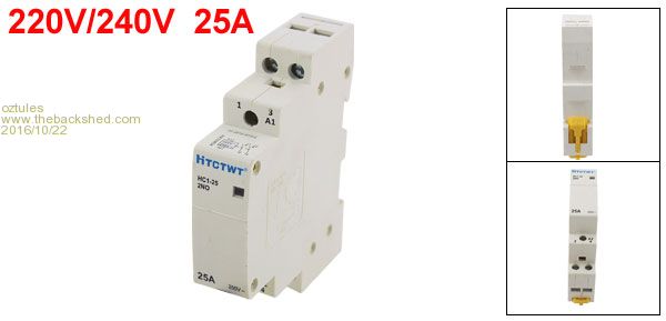
I would use this sort of relay...

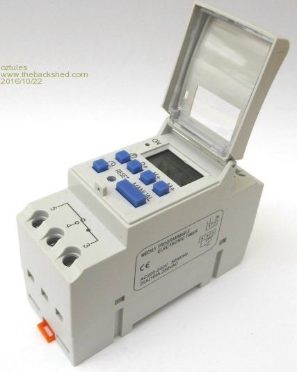
This sort of timer .... should only need one as it has multiple multiple programming. and does not forget programming when power goes off for some reason... self resets when power resumes.
I note there are some of this design that claim 20 amps, and this would mean no relay required for a 2hp centrifugal pump motor

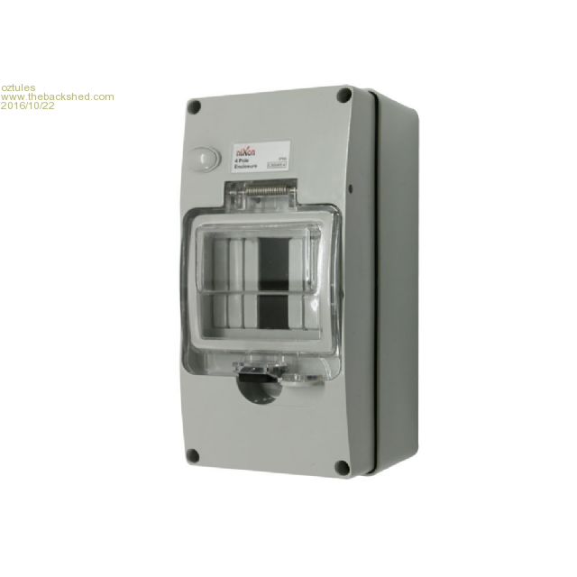
I would keep all components in this style enclosure ... and all at 240v not 12 or 24 etc.
This sort of box has water proof ratings, and it has the din rail so all the stuff will all just clip in. There is room under the rail for wiring as well between items, and gland exits too.

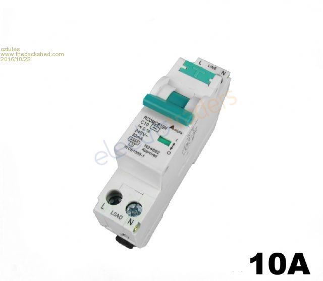
and a 1 pole rcd.... just because you can 

Mount on a stand pipe/pole next to pump, and a float switch of your choice to suit in another weather proof box same style would look nice.... but I would use this sort of float with no box required, and will never fail. They have natural hysterisis which may suit your requirements

This will only require a single lead from your power point at the house.
I would not use solid state relay in these circumstances... they fail "on".. and with an inductive load like that... failure is a distinct possibility sometime.
This would be robust and very unlikely to fail, simple to implement, and very neat and safe.
............oztules
Edited by oztules 2016-10-23
Village idiot...or... just another hack out of his depth |
| |
domwild
Guru

Joined: 16/12/2005
Location: AustraliaPosts: 873 |
| Posted: 08:11pm 22 Oct 2016 |
 Copy link to clipboard Copy link to clipboard |
 Print this post |
|
Thanks for answers, especially the extensive one from oztules.
joebog1: The tank is filled from the roof and also from the next-door quarry as compensation for the dust we are eating.
There is one solenoid where the pipe enters my block as the garage next door has power and that solenoid opens the quarry supply via a time switch. The supply pipe is also used as the delivery pipe should I need the pump for more pressure. Hopefully the solenoid will stop the water from going back to the benefit of the quarry as those irrigation solenoids have the nasty habit of opening in the reverse direction if the pressure is too high. But the quarry pressure comes off a hill and should be even greater than pump pressure.
To stop the tank from overfilling with the quarry water during the filling time as given by the timer in the garage I have a solenoid at the tank and unfortunately these solenoids run at 16VAC. There may be 240-16VAC DIN-rail mounted transformers available, I have not looked so far.
My SSR is built for 45A for the pump but you do not trust those SSRs then? The Indian-built pump has a 10A plug on it, which looks illegal and gets hot even during test running.
Thanks for the photo of those float switches, I had my eye on them but could never find out if those tiny reed switches in them can carry the 15W (?) at 16VAC those solenoids require.
Thanks for photos.
Taxation as a means of achieving prosperity is like a man standing inside a bucket trying to lift himself up.
Winston Churchill |
| |
joebog1
Senior Member

Joined: 07/11/2015
Location: AustraliaPosts: 114 |
| Posted: 08:54pm 22 Oct 2016 |
 Copy link to clipboard Copy link to clipboard |
 Print this post |
|
The "stuff" oztules has described is all fine. AND as far as I can see, is legal.
16 volts AC works, but is very amateur-ish. By adding transformers or wifi chargers reduces reliability, complicates things, and makes it double difficult should "someone else" ( fire department, friend, etc etc) need to debug the system in emergency. Remember the KISS principle !! ( er hhmm without any offense intended,
KEEP IT SIMPLE, STUPID)
The MOST reliable, the most functional, and USUALLY the cheapest way, is also the simplest.
Pressure controlled non return valves ( very similar to a foot valve ) are cheap, and VERY effective for "back pressure/ over pressure, and some can be setup so that the best pressure is always the feed point used. As far as "float" switches are concerned, today there is a multitude of systems available, from fancy wifi, battery operated disasters, to capacitive sensors that are VERY reliable, use almost no power, and consequently require small control cables to operate.
The BEST way to position the pump would be to place the pump AND its power supply ( power cable, dare I mention an extension cord  ) at the source of the water, and pressure feed the water to where its required, EVEN if its only a few pounds pressure ( what pounds is expressed in, with kilograms per centimetre squared wasnt taught at my school in the 1950,s) BUT electricity travels the SAME speed today, as it did when I was a kid ) at the source of the water, and pressure feed the water to where its required, EVEN if its only a few pounds pressure ( what pounds is expressed in, with kilograms per centimetre squared wasnt taught at my school in the 1950,s) BUT electricity travels the SAME speed today, as it did when I was a kid  , so hence my attempt to offer some help. , so hence my attempt to offer some help.
If the tank is filled from the roof ( like mine) it uses gravity and doesnt need a pump. BUT the water from the irrigation channel uses a Davies unit, and the power supply ( 4mm^2 ) is underground in orange underground conduit.
ALL the sensors and ancillary equipment is also fed from this supply, which services five houses with all water OTHER than drinking water ( as I listen again to that bastid in his airplane spraying who knows what into the open channel while the banana growers drink champagne )
Joe |
| |
oztules

Guru

Joined: 26/07/2007
Location: AustraliaPosts: 1686 |
| Posted: 09:35pm 22 Oct 2016 |
 Copy link to clipboard Copy link to clipboard |
 Print this post |
|
Those float switches are rated @ 15amps 380vac
I think they are most probably mercury switches.
1500w motor can use it's 6-7 amps running, but will use peaks of 40 or more amps on start up. The triacs in the ssr will carry this, as their surge is very high, and triacs are very rugged, so the short surge will mostly be fine..... should the bearings get a bit tight or foreign material in the pump head slows the start then the high current may persist beyond the ratings of the ssr.... it should be fine.... but I trust a relay more long term on a big motor as the failure will likely be motor off not motor on and maybe struggling to start.. or with the ssr.... we get going... and empty the tank, and cook the dynamic seals.
Personal choice.
You may find that the coils on the irrigation relays/solenoids are replacable with 240v one with a single nut releasing the coils for replacement.
A 2 or 3 watt transformer will fit one of those boxes easily anyway, but gets more expensive with more stuff.... don't use 16vdc (eg cheap led "transformer... which is really a pwm supply or modern wallwart... also dc). All the modern wall warts are pwm now... much cheaper to manufacture, and voltage stable like transformers never were... so DC as a generality
The solenoid valves are normally only suitable for high pressure to low pressure in one direction only. They use the water pressure differential to open the valve... this allows a small magnetic field to move a small billet/piston over a tiny pinhole to initiate stop or start... reverse flow does not need to be very much at all to leak backwards.... when working with the salt water reverse osmosis unit I built for an outer island, I found the brass chinese valves worked better than the expensive american plastic ones ( made in Mexico actually for an american brand name) that came with the membrane and pump from USA... I replaced them all.... it was trying to find out why they were erratic, that I became fairly familiar with their mode of operation.. or lack thereof.
.............oztules
Edited by oztules 2016-10-24
Village idiot...or... just another hack out of his depth |
| |
domwild
Guru

Joined: 16/12/2005
Location: AustraliaPosts: 873 |
| Posted: 12:53pm 23 Oct 2016 |
 Copy link to clipboard Copy link to clipboard |
 Print this post |
|
Thanks joebog1 and oztules for the many tips. Looks like a 240VAC coil and a mercury-based float switch is the simplest way to go and gets rid of a DIN-rail 16VAC transformer or separate bulkier one on a socket and a floatless level switch.
Have thought a SSR switching on at zero voltage and switching off at zero Amps is the way to go but I bow to your experience of fixing everything up that has failed around Burnie Island and other islands!
Taxation as a means of achieving prosperity is like a man standing inside a bucket trying to lift himself up.
Winston Churchill |
| |
oztules

Guru

Joined: 26/07/2007
Location: AustraliaPosts: 1686 |
| Posted: 09:28pm 23 Oct 2016 |
 Copy link to clipboard Copy link to clipboard |
 Print this post |
|
This is just an aside really,
"Have thought a SSR switching on at zero voltage and switching off at zero Amps is the way to go"
If you think about whats going on, we can see that a stationary induction motor is really the same as a short circuited transformer.... hence the very high start currents.
From previous discussions you may have read on here, zero cross over is the very worst place to start a transformer on the sine wave.... it is much preferable to start it on the peak voltage of the sine wave, and then it will behave as the idle current of the transformer..... at zero crossing start, a decent sized torroid will always blow every fuse in the line, as it tries to use about 60 times it's idle current... and thats with no load... I don't know the figures for short circuit start, but assume they would look terrible. A motor is very leaky compared to a torroid, but you get the drift.
To add insult to injury, we usually wind transformers/motors close to saturation, to keep costs and weight down, so at zero crossing, current is at maximum ( x 15 for normal transformers, x60 for torroid... with no load applied!). so when we start at zero crossing we saturate for part of the cycle/s ( quite a few cycles until it stabilises)...now we are non-linear..... and this produces it's own problems with spurious harmonics that can cause havoc with silicon components... every start will be slightly different, and the saturation will last for different periods.. can you see where the problems start to become more than just inconvenient load spikes.
Looked at another way, if we are saturated ( and we will be), then it is the resistive component that will dictate the current, so a 2hp motor may be in the range of 4-5 ohms so I = in excess of 50A at that point... not including the start field which will be out of phase too.......
The rotor is a shorted turn of many thick copper bars....until it gets rotating about 2/3 of the slip speed, when currents start to get back under control.
A resistive load works as you presupposed, but not a transformer/ induction motor.
There has/had been a sea change around the turn of this century to solid state starters instead of centrifugal switches, and even in fractional horsepower sizes.. it is/was very common that the starter pack had failed.. and they are purpose designed not to.
I have not seen them recently... maybe they have stopped using them now.... don't know, just have not seen them in the last 10 years over here. Maybe others can comment.
If you could get it to start on the peak of the wave, things would be very different I suspect.
...........oztules
Edited by oztules 2016-10-25
Village idiot...or... just another hack out of his depth |
| |
joebog1
Senior Member

Joined: 07/11/2015
Location: AustraliaPosts: 114 |
| Posted: 11:00pm 23 Oct 2016 |
 Copy link to clipboard Copy link to clipboard |
 Print this post |
|
A toroid started at zero with full load "can" take 400X its rated full power current!!
about 2 cycles worth. A toroid is not really a good example as its "almost" 100% efficient, in fact @ 2 HP or thereabouts ( 746 X 2, assuming perfect example, without losses)1500 watts divided by 240 volts.
There are "soft start" devices to prevent this, BUT taking oztules examples of,
1 tight bearings
2 crap in the pump rotor
the resistor used usually burns out. There are solid state ones, but I havent seen one. Yet !!!.
Relays are still around after more than 125 years for a reason. Simple and bloody reliable! Cheap and very easily replaced.
hhmmm I did quite a study on toroids when they were first released, for sound duty, as I am pretty much an audiophool, and was looking for perfect valve derived sound. Perhaps why I still use EI laminations in audio, albeit bloody big ones.
oztules meanderings about SSR switching is spot on however.
Joe
|
| |
oztules

Guru

Joined: 26/07/2007
Location: AustraliaPosts: 1686 |
| Posted: 01:23am 24 Oct 2016 |
 Copy link to clipboard Copy link to clipboard |
 Print this post |
|
"
hhmmm I did quite a study on toroids when they were first released, for sound duty, as I am pretty much an audiophool, and was looking for perfect valve derived sound. Perhaps why I still use EI laminations in audio, albeit bloody big ones."
This is off topic... but I can't help it.... I like valves.
I expect torroids for the power supply would be a straight forward project, good regulation, and half the mass of an EI for the same power...as you don't need supporting steel around the core... there is only the core.... so an obvious improvement.
I would expect the problems to begin when we go to output transformers, as the torroid takes no prisoners, so perfect bias balance would be needed, and drive, but saturation would be a ever present threat at low frequencies, so the mass of the torroid may well be near as great as the EI version...to avoid saturation at low frequencies.
The torroid would not allow for any imbalance of the AC or DC in the windings..... but if you could trim it up properly.... would be the best transformer for the job.. . perhaps the C core would be the best/simplest practical solution.
I would not like to try to wind a torroid with the interleaved windings and balance for a williamson ultra linear any time soon.
And this is pure insanity... but gee I like it.....

..........oztules
Village idiot...or... just another hack out of his depth |
| |

