
|

|
Forum Index : Electronics : ozinverter improvements
| Page 1 of 2 |
|||||
| Author | Message | ||||
| jdevine82 Newbie Joined: 01/09/2016 Location: AustraliaPosts: 13 |
Hi All I recently saw a self destruct mode of a powerjack powerboard when some wires were fried in a fire Graham had in his shed connected to one of our inverters. I know oztules has commented that the current limit mode of these inverters is a little slow and since we have torroids instead of e-core leading to over-current events before the shutdown of the primary drive in a secondary short event. The question is what could be done to stop this kind of event. I am thinking a 75mv shunt between the mosfets and the transformer and some instrumentation amp. Then some direct feed into the drivers (currently the ir2110 but that may need to change).. It will get complicated in startup events and the like I assume.. What does everyone (&oztules) think? Is this the correct way to go about it? Jason |
||||
oztules Guru Joined: 26/07/2007 Location: AustraliaPosts: 1686 |
Yes, when the pj blows, it usually takes a few bits from the mother board as well. I have not had anything happen to the controllers of the current units I build... not even the drivers so far. I have blown a few up now trying to find out about the current shut off schemes... so an expert blower upperer now. None have failed in normal use happily. I purchased a few of the commercial 002 units ( 5000w 48v) for about $100 a piece, and thought they may provide the answer because they run a pulse by pulse primary side current limit circuit.... and with a torroid, they still blow the fets up just as well as AC side current limit... and for the same reason, the CFB pin can be fooled easily enough... so any comparator on the ac or dc side that shuts it off unequivocally on any pulse over setting will work...so really a diode between the output of the comp, and the input sense pin will work... then it needs to be reset manually... like an at style power supply ( that uses scr ... same effect ) ..........oztules Village idiot...or... just another hack out of his depth |
||||
| jdevine82 Newbie Joined: 01/09/2016 Location: AustraliaPosts: 13 |
Hi umm I see. I think a actual scr will have a forward voltage of over .5v that the CFB pin is looking for so maybe a simple transistor cicuit added to your current feedback network like this.. amended circuit with CFB latch Jason |
||||
Grogster Admin Group Joined: 31/12/2012 Location: New ZealandPosts: 9308 |
Now would be an exceptionally good time to know what to do with this, as I am designing my own controller board. 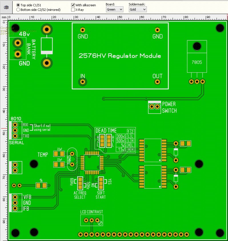
This is still a work in progress and is not finished, but it is on a 100x100 PCB, which are cheap as chips to have made. The current and voltage feedback are on another board: 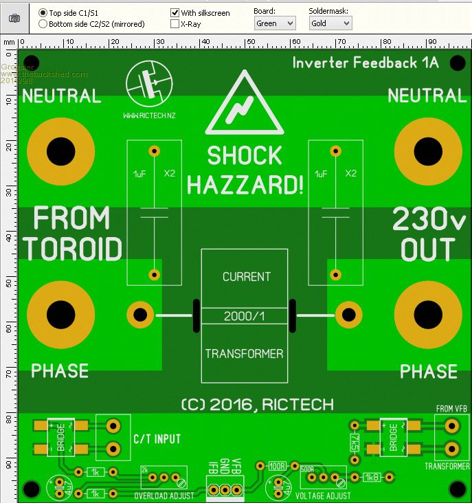
This controller board design has the ST7920 LCD module mounted on the front-facing side, so the board will display the vitals of the inverter without needing additional external voltage and current sense boards or modules: 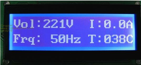
I am using the IFB input as-is now, but if this is a potential source of problems, it would be nice to be able to design this transistor buffer into the PCB layout if it works. I can design the layout to accomodate it, and have some solder-blob pads to bypass it I suppose, but it would be nice to incorporate an improvement in the design if you guys have come up with one. 
Have you tried it? Smoke makes things work. When the smoke gets out, it stops! |
||||
oztules Guru Joined: 26/07/2007 Location: AustraliaPosts: 1686 |
Jason, That should do it..... but... " I think a actual scr will have a forward voltage of over .5v that the IFB pin is looking for so maybe a simple transistor cicuit added to your current feedback network like this.." Well no... for 2 reasons. 1. We can use IFB, we can use TFB, we can use pin 6 IFB is probably the nice one to use as it will indicate over current event.... but adds extra set time to the event triggering shut down... built in the chip... may not be fast enough for us. 2. However, if you look at your circuit, we actually have a floating drive supply made from the CT and rectifiers, so we can use the SCR channel A-K to pass current to the ?pin on trigger signal (eg. between +5v and the IFB pin irf you want to ...), and we can use an isolated supply from the CT to be the trigger .... and a press switch across the SCR for reset.... so really only 1 extra component.... and a reset switch. I like simple and robust, however your solution is valid too. I will use the temp pin for first tests ( gun shy of the IFB pin at the moment ), and then if that works, the IFB pin next. ( but the built in timer has me bothered, this is a catch all over load we are talking about, I think virtually instant is required) EDIT I changed CFB to IFB as Grog has indicated correctly... what was I thinking.... .........oztules Village idiot...or... just another hack out of his depth |
||||
Grogster Admin Group Joined: 31/12/2012 Location: New ZealandPosts: 9308 |
We all knew what you meant by CFB I expect. 
So you like the SCR idea, Oz, so sounds like you are going to do some tests there, so please do let the thread know if it works or not, as it would be awesome to include that into the layout if I could. The board is still a week or two away from being finished as I only do a little on it when I feel like it, so no rush but it would be fantastic to know that this works if it does, and incorporate it into the overall layout. Smoke makes things work. When the smoke gets out, it stops! |
||||
| jdevine82 Newbie Joined: 01/09/2016 Location: AustraliaPosts: 13 |
Ok, I see that running the scr to the ct is a novel idea! What do you recommend for this? You know repeatable testing and all. Unfortunately all my torroids are in use at moment so will be a few weeks at least before I have another up for testing.. Jason |
||||
oztules Guru Joined: 26/07/2007 Location: AustraliaPosts: 1686 |
Grogster, If and when we get this o/load business idiot proof, then the inverter will really be ready for prime time. It is the only thing holding it back from being excellent rather than very acceptable. It can drive all loads, has very high power output, if we can just get a safe way of limiting it from shorts, I will be very very happy.... pretty darn happy now. Yes I like the SCR idea, has a crowbar feel about it, and it is the crowbar of choice in millions of AT and ATX power supplies.... it just works. Jason...there is no easy way of saying this... we build it, we blow it up It needs to have a grunty torroid there, so we can see how the back MMF and EMF are going to operate.... it is easy to get the leaky transformers to work , it is getting the torroids to work on the same page thats the challenge. Perhaps a power board with 4 fets will do, as they will be frail and easy to intimidate....... and replace. .........oztules Village idiot...or... just another hack out of his depth |
||||
Grogster Admin Group Joined: 31/12/2012 Location: New ZealandPosts: 9308 |
My power board will use the HY4008 MOSFET's in TO247, just cos I like those packages better then the TO220 ones lots of other people have been using. This is NOT to speak ill of the TO220 devices - they seem remarkable considering what they are doing! 
I plan to use two banks of these(eight in total), as my inverter is only designed to provide about 3kW total output, usually much less even then that. I will probably end up using three banks(twelve MOSFET's) just for a bit of extra headroom and capacity over and above what I will ever need, to make the power board a bit more bullet-proof. I doubt I would need more then three banks, but Oz would be the person to chime in now if he thinks I should be using more, but when my inverter project is not quite as juicy as the rest of you guys' 6kW versions....... Smoke makes things work. When the smoke gets out, it stops! |
||||
Grogster Admin Group Joined: 31/12/2012 Location: New ZealandPosts: 9308 |
This is how I see Oz's SCR idea: 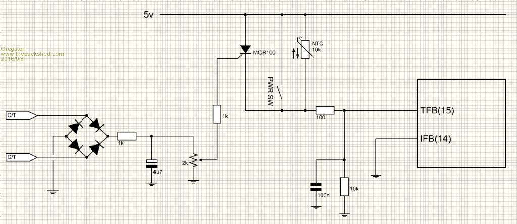
As per the 8010 manual page 13, if we ground IFB pin-14, then that disables that aspect of the 8010 controller chip, and then you would just use the SCR across the power switch and NTC temperature sensor. In an overload situation, the SCR gate voltage would rise above 0.62v or so(the gate trip threshold for an MCR100), which would fire the SCR, and pull TFB pin-15 high, which would immediately force the 8010 controller to think there was something seriously hot, and it would shut-down the inverter. From what I can see, this is EXACTLY how you guys are actually turning your inverter design off and on anyway - the power switch just shorts out the NTC, and thus "Open is on" kind of thing. IE: If the power switch is open, the inverter is on. If the power switch is closed, the inverter is off. I expect the LED is also blinking it's temperature alert sequence with the inverter off. I will probably have a master 48v supply line power switch to completely isolate the 48v from the circuit for my on/off. Smoke makes things work. When the smoke gets out, it stops! |
||||
| Tinker Guru Joined: 07/11/2007 Location: AustraliaPosts: 1904 |
Not quite so with my inverter. I used pin 6. Pin 6 to +5V = on Pin 6 to ground = off This require a SPDT switch, most of them are anyway. Klaus |
||||
| jdevine82 Newbie Joined: 01/09/2016 Location: AustraliaPosts: 13 |
Grogster wouldn't you need to make the current sense circuit float at the potential of the switch as to not interfere with the temp sense? I think that is what oztules was suggesting... Not sure how a negative gate voltage works on a scr.. like this more scr drive Tinker this is direct into the EG8010 not on the EGS002 board so the chip doc says high is off and low is on for temp shutdown pin.. Jason |
||||
Grogster Admin Group Joined: 31/12/2012 Location: New ZealandPosts: 9308 |
@ Jason - You may well be right - it is 1:30AM here, and I need sleep. 
I don't tend to think that well at this time of night, so time for rest. Catch ya all on the flip side...... Smoke makes things work. When the smoke gets out, it stops! |
||||
Madness Guru Joined: 08/10/2011 Location: AustraliaPosts: 2498 |
The board Tinker mentioned is a later version as attached, it has the on off switch attached to pin 6 of the 8010 chip. You can read more about it here 2016-09-08_211322_80109f_1.pdf There are only 10 types of people in the world: those who understand binary, and those who don't. |
||||
oztules Guru Joined: 26/07/2007 Location: AustraliaPosts: 1686 |
Jason, thats the simple addition I had in mind. The floating CT supply is very handy here. As I stated on another thread, it is to be seen if the temp pin is fast enough... ie how often is it polled... or is it an interrupt etc. If too slow, then the inhibit of the driver 2110 can be driven via isolation diodes from the scr to the 8010 and 2110 simultaneously.... The temp pin will have needed to be pulled high too, so soft start will occur when you hit the reset switch. This means the filter caps in the CT circuit will control time to shut down, as everything else is instant. .........oztules Village idiot...or... just another hack out of his depth |
||||
Grogster Admin Group Joined: 31/12/2012 Location: New ZealandPosts: 9308 |
How about something like this:(copying from jdevine82's idea) 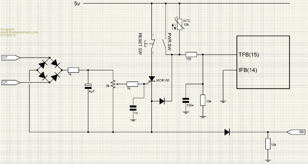
C/T floating supply triggers the gate of the SCR when it's gate voltage goes above about 0.62v(for the MCP100 SCR), which causes the SCR to turn on, which pulls both SD pins of the 2110 driver IC's high via a gating diode, which inhibits the drivers. At the same time that happens, the TFB pin on the 8010 is pulled high via another gating diode, which stops it flat in it's tracks with what it thinks is an over-temp issue. The diode idea is Oz's, and I think I have that right in what he was thinking? With the SCR now turned on, there will be a constant potential on BOTH leads of the C/T(via the bridge with the SCR on), but with no path to circuit ground, that won't matter I don't think(because no current can flow). With the SCR in the off state, the 10k on the SD line pulls the SD lines of the 2110 driver IC's low to enable them in normal use. Do we need the 1n on the SCR gate? To reset, you just press the reset button, which interrupts the 5v to the SCR, and it will "Reset", the voltage will vanish from the cathode of the SCR, and the NTC will allow the 8010 to restart, and the 10k pulldown on the 2110's SD lines will re-enable them. Thoughts? Smoke makes things work. When the smoke gets out, it stops! |
||||
| jdevine82 Newbie Joined: 01/09/2016 Location: AustraliaPosts: 13 |
Looks good to me.. I wont have a transformer to test with though for a little bit though. Jason |
||||
Grogster Admin Group Joined: 31/12/2012 Location: New ZealandPosts: 9308 |
Cool. I will run with this then, but waiting for Oz to chime in with his thoughts.... The datasheet for the 2110 driver IC's says that the SD pins will effect an inhibit of the drivers within 140ns maximum, which is just a tad faster then relay contacts take to open or close, it has to be said. 
I cannot find any details on how long it takes for the SCR to conduct via the A-K path once the gate threshold voltage is reached, but if I find that out, I will post it. The MCR100 datasheet does not specify the propagation time, only the gate threshold voltage. I might look for another datasheet for that device, but I expect they are probably all the same. Smoke makes things work. When the smoke gets out, it stops! |
||||
oztules Guru Joined: 26/07/2007 Location: AustraliaPosts: 1686 |
Yep, an scr, two diodes and a pull down resistor will do it ... looks like a plan.....now, who's jamming the screw driver in there to test this 
But, if that does not shut it down fast enough and deliberately enough, I'm not sure what will. The 2110 has a pull down internally I think, so maybe even no R required... ie SD does not require a connection if not used ( from looking at the internal schematic)... not sure of the value though... will have to find the sheet again. 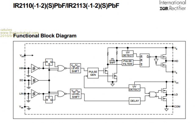
...........oztules Village idiot...or... just another hack out of his depth |
||||
Grogster Admin Group Joined: 31/12/2012 Location: New ZealandPosts: 9308 |
I have the 2110 datasheet, so am looking at the same block diagram you posted above, but nowhere in the datasheet does it specify what those pulldown resistor values are. I guess it would be easy enough to find out by measuring the resistance of that pin to ground of an uninstalled chip. I expect it would probably be in the area of 100k or so. Although, that is not a rock-solid test either, as any other current paths via the chips' internals to ground could affect that reading. It would have been nice if they had stated what that value was, but I could not find it anywhere in the datsheet. 
In the other threads where you talk about bypassing the op-amp on the 002 module by removing the op-amp chip and installing a link between pins 1 and 4, you are pulling the SD lines down to ground in doing that. Obviously it was necessary at that time - do you think you could get away with removing the op-amp and NOT installing the link wire on the 002 module? Just curious about that now....... For now anyway, I will design the layout to incorporate the SCR and diodes plus one pulldown resistor on the SD lines of the 2110 drivers, as everyone seems to agree that this is an OK idea in theory. I had to get the approval of the master(Oz!) before I included that, as he is the Inverter Guru here.  Smoke makes things work. When the smoke gets out, it stops! |
||||
| Page 1 of 2 |
|||||