|

|
Forum Index : Electronics : Charge Controller with Grid Tie criticism
| Author | Message | ||||
| arpolis Newbie Joined: 04/08/2010 Location: United StatesPosts: 26 |
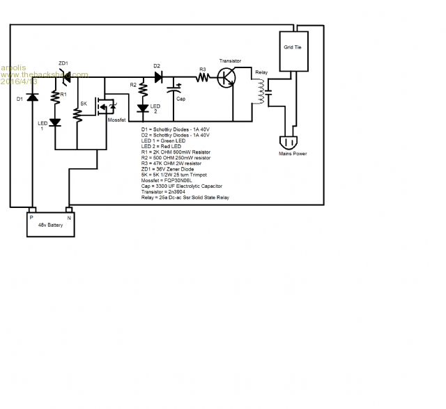
Hello everyone I am very novice when it comes to electronics with no proper schooling. But I like to tackle hard subjects, deconstruct other projects and reconstruct into my own ideas. I wanted to build a charge controller with a few things in mind. After about a week of studying I came up with the following. Everyone feel free to be brutal and correct anything I do not have down correct. First off there was a few things I wanted to center this around: 1) 48V charge controller 2) Does not disconnect wind turbine or solar from batteries but rather connect a load. 3) Uses one trim pot for a set voltage to start draining battery. 4) Runs the load on a timer for 4 - 6 minutes that starts counting down once battery gets below trip voltage. 5) Takes advantage of grid tie inverter. Here is my circuit diagram: 
The idea is that the 48V battery bank is reduced down to the proper voltage to activate the mossfet via the Zener and trim pot. LED1 to show in charge mode. Mossfet then opens up 12v circuit to capacitor that holds charge. LED2 shows dump in progress. While mossfet is open the relay connects the positive sides from grid tie power cable so the grid tie starts pulling watts from the battery bank and injecting into the grid. This assuming the grid tie has proper "island protection" so that when it is off it is not drawing watts when the mains power is not connected. When Battery voltage drops and the mossfet shuts down power the capacitor now bleeds energy to the relay until depleted. I understand to get proper timing to the specific battery bank so as to not over discharge the capacitor or R3 values may need to be adjusted but I choose these for just ballpark guesses based on videos watched. Anyone see any issues with the circuit? Am I over complicating things? Am i under complicating things? Any thoughts or criticism will be greatly appreciated. Will it work? Well lick your fingers and touch the two leeds. PZZZZZZZT |
||||
| Gizmo Admin Group Joined: 05/06/2004 Location: AustraliaPosts: 5078 |
The circuit has a number of faults in the drawing, especially around the mosfet and the transistor. You would be better using an existing working circuit and start from there until you get a better idea on how things work. Google voltage controlled relay. Glenn The best time to plant a tree was twenty years ago, the second best time is right now. JAQ |
||||
| arpolis Newbie Joined: 04/08/2010 Location: United StatesPosts: 26 |
Thank you Gizmo I am still trying to get the hang of this. The circuit is a near copy and paste of other circuits pieced together. I know there is a lot more I need to learn. I am just trying to get pointed in the right direction as to what faults I need to correct and what to learn. For sure I will start with a known charge controller when I go bigger in my shop. I have been playing with home built wind generators with varying degrees of success and built a couple solar panels on my fathers shop. The system I built for him keeps some cokes in a mini fridge cool for him. It is using a cheep solar charge controller from ebay. I found a 48V version of the Ghurd controller online sold in a DIY kit that looks promising to turn on a bank of resistors the way I want. So I will not try and be a magician and make any magic smoke any time soon. Just while in between projects my mind wanders off into uncharted territory and wants to start learning. I'll start googling again. Thanks a lot. Will it work? Well lick your fingers and touch the two leeds. PZZZZZZZT |
||||
sparksandsmoke Newbie Joined: 14/05/2015 Location: IrelandPosts: 12 |
Hello arpolis Your specification is very vague, would you expand on it, and/or reword it? I suggest that you break your spec. (and your project) down into smaller "subsections" initially. It'll be easier to understand and you'll be in a better position to diagnose (fault-find) as you will be taking a more methodical approach. One thing I feel obliged to say, though. Please stay away from anything "grid tie" until you've mastered the basics. A long and active life may well depend on it. |
||||
| KarlJ Guru Joined: 19/05/2008 Location: AustraliaPosts: 1178 |
grid tie bit is a piece of cake, simply buy a pair of Enphase microinverters. They happily run 24V batteries (i have a pair running RIGHT NOW in parallel off a 24V lithium battery) connected in series will run 48V should be no worries although i haven't tested this config. plenty of other 48V to grid inverters out there but i dont think OZ has done too much with GTI stuff, preferring slip angles (ie squirrel cage motors) to dump power to the grid for sh*ts and giggles. correct me if im wrong! (aside from missing "r" as my keyboard is tempremental with that letter) RE charge controller DC-DC converters do a great job of AUTO MPPT but! you can buy charge controllers on ali/ebay for utter peanuts thus not worth your time K Luck favours the well prepared |
||||