|

|
Forum Index : Electronics : building an Inverter from scratch
| Page 1 of 25 |
|||||
| Author | Message | ||||
| Tinker Guru Joined: 07/11/2007 Location: AustraliaPosts: 1904 |
Oztules and others have done all the pioneering work about how to build a really good pure sine wave inverter using the EGS002 inverter driver board. I decided to build one too and have ordered that EGS002 board. But I do not want to copy oztules PCB (I don't have that program anyway), I rather do my own layout. And I can see a few not so good features with the PJ style power board so I do not want to copy that either. But circuits for a complete inverter with the above driver board seem to be non existent in a simple form. I found lots of relevant info on that Otherpower site and from that I have drawn up this circuit: 
Now, I'm sure there is something I have overlooked so I like to ask if those who know more about inverters than I do would check this circuit for me. I am aware that I only drew one mosfet per leg, in reality there would be up to six. I did not want to clutter up my drawing like some that I have seen. Thanks. Klaus |
||||
| Clockmanfr Guru Joined: 23/10/2015 Location: FrancePosts: 429 |
Hi Tinker. Have fun and I will chip in where I can. I have changed the 4r7 resistors for 5r6, diode is okay on the IRFB4110 Fets. Sorry about lack of schematics, but I just draw the bits first and route as I go. The Control Board with the EG8010, and must have HT1536 on the last of the serial number on the chip. The complete EGS002 board has these chips, but it seems there are about 20 other numbering sequences for sale, and each is programmed differently. On the EGS002 board remember to disable those amps with a sharp knife, see Oz's notes. Power boards, I have gone for the full 15kW board. My copper on the board will be subject to 250 amps at 50 volts DC. Now that's in Heavy engineering and not normal PCB's. PJ had problems with there staff assembling soldering and now go for Sub boards so PJ Staff skill is not so important...... Cooling is very important so the Power board and Control board should, in my opinion, be laid out to assist forced/fan Air flow over the complete Boards. I have, we Oz, have done away with the CT, its a weak link and I hate mixing AC with DC on the same card. Like your schematic, We Use a sense coil around one of the AC output cables and duly rectified on the control board. No need for stonking great AC connections as PJ stuff. Everything is possible, just give me time. 3 HughP's 3.7m Wind T's (14 years). 5kW PV on 3 Trackers, (10 yrs). 21kW PV AC coupled SH GTI's. OzInverter created Grid. 1300ah 48v. |
||||
oztules Guru Joined: 26/07/2007 Location: AustraliaPosts: 1686 |
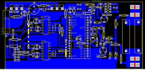
Nice to see this turn up here...... I was going to do a full how to, but may not have to now. Yes that circuit will ( for all it's simplicity ) do a perfectly good job.. every bit as good as the PJ, and anything else running around the world. Provides solid power, usually less than 1 volt drift (0-5kw), and clean sine wave.... but to do that you still need the 2uf across the AC out. Further filtering for those who like clean airwaves ( Ham radio guys) is necesary, but your inspire innards can contribute that. I would go one further and just use three chips and the fets, and this works equally as well, and no 002 boards required..... feels more like you own it... mine plug in so if the worst happens, I just unplug 3 chips, and replace, and were away too. I admit the 002 board is every bit as simple, and has anti cross over protection. The suffix clockman refers to is for uvlo. It does not exist in the HT1533 chips I bought, but does in the HT1536 ones... I cold not et mine to uvlo... and wondered why. I think the PJ power board could be better, too, but in reality, it is hard to beat it, so a simple rework is all that may be required... I have thought long and hard at all the different styles I cold use for the H bridge..... but I keep comng back to that general layout, or a planer version... ie flat heat sin style.... but still the elegant way of using the heat sinks for solid connections is hard to pass up.... so I will stick to the PJ style.. My latest one is this one.......well it was to be but the upload does not take .png (Maybe that windowcentric owner will finally give in and give us linux folks a chance) Anyway, pictures are on the anotherpower site eg different styles here: http://www.anotherpower.com/board/index.php/topic,1116.120.html This has been running for a week or so too. It is amazing to think it can be so easy. .............oztules Village idiot...or... just another hack out of his depth |
||||
| Gizmo Admin Group Joined: 05/06/2004 Location: AustraliaPosts: 5078 |
I'll have to look into this. The image resize routines never had the ability to handle png files. I guess png wasn't that common when I put it together. Glenn The best time to plant a tree was twenty years ago, the second best time is right now. JAQ |
||||
oztules Guru Joined: 26/07/2007 Location: AustraliaPosts: 1686 |
maybe look at small pdf as well... for circuit prints. ok I persevered and did the jpg conversion so here it is now 
Note the there is only three chips, all plug in. The 8010 can be replaced by the folks on the mite board.... they are smarter than me, but a i figure a jump table and scaling is really all that is required to make a useful chip.... but at $1.50 and less per 8010... I just could not justify the programming on even a nano... I cant get a burnable chip for that kind of money. This route is a close to home brew as you can get without programming a chip yourself. A proper buck converter or similar would be better so as you can drive the fans..... but also a tiny 240v transfromer will do fine too. .........oztules edit... there is a pic similar on anotherpower, when you click it, and it will blow up full size so you can see it properly Village idiot...or... just another hack out of his depth |
||||
| yahoo2 Guru Joined: 05/04/2011 Location: AustraliaPosts: 1166 |

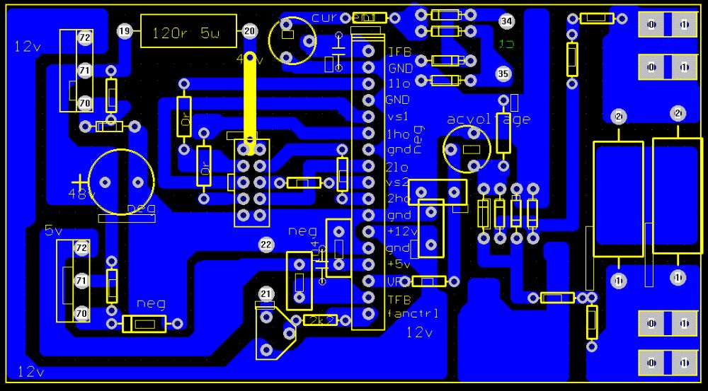
the *.gif file type works OK for detailed viewing I think this is the last version of the ESG002 pcb for comparison. what does VS1 and VS2 do? are they sensing the crossover point? there are no components just wondering if it is important that they have similar paths. I'm confused, no wait... maybe I'm not... |
||||
oztules Guru Joined: 26/07/2007 Location: AustraliaPosts: 1686 |
VS1 and VS2 are simply the floating "source" points for the 1Ho and 2Ho gate drives ... ie gate voltage reference point/s. The charge pump pushes the voltage beyond b+ to drive the gates of the high switches, and this is the gate reference at the source of those high side fets... ie when the fet turns on, there is no potential between drain and source, so source will be at b+ when turned on... so we need higher voltage to hold the gate on. The low sides use ground for this reference. I believe normal analogue practice is not required here, and ground loops are acceptable... you want 1's and 0's @ 12v.....so noise on the line is of no interest.... within reason.... so earth points everywhere are best. Yes that is the last version I think... works perfectly well, but I have swapped to 8010 alone now. Got more drive boards than I can poke a stick at really... .............oztules Village idiot...or... just another hack out of his depth |
||||
| Gizmo Admin Group Joined: 05/06/2004 Location: AustraliaPosts: 5078 |
You can upload png's now. Thats should keep all those weird Linux guys happy 
Resized the same as jpg, to 500 pixels wide. I think I might review that 500 pixel sizing, maybe 640 pixels for JPG/PNG and 1024 for GIF. Glenn The best time to plant a tree was twenty years ago, the second best time is right now. JAQ |
||||
oztules Guru Joined: 26/07/2007 Location: AustraliaPosts: 1686 |
Thanks Glen 
..........oztules Village idiot...or... just another hack out of his depth |
||||
| yahoo2 Guru Joined: 05/04/2011 Location: AustraliaPosts: 1166 |
the only thing I can see Tinker is your +12v and +5v supply to pin 14 and 12 is not in your circuit. Where are they sourced? It is no good me looking at the component values, I am hopeless without a reference to prompt me. I'm confused, no wait... maybe I'm not... |
||||
| Tinker Guru Joined: 07/11/2007 Location: AustraliaPosts: 1904 |
Yes, the sources are not shown deliberately for drawing clarity reasons. I will use one of these e-bay buck converters from 48V nom. battery voltage to 12V to drive the fan(s). And then a 7805 or similar to get 5V from the 12V, like oztules did. Yes, no output capacitors or other suppression parts are drawn either for the above reason. I plan to insert them where they are most effective later, after all this will be a prototype board. When I finished drawing it up it looked too simple so I thought better ask here... Thanks folks, your input is much appreciated. What I do *not* like with the PJ board is the life heat sinks, too easy to have a magic smoke accident. I have two of those gigantic 3Kw Aero=Sharp heatsinks, one of them should be more than adequate to handle the power I am aiming for. The plan is to insulate each mosfet and mount them on 6mm x 50mm alu sub carriers which in turn are bolted to the big heat sink. There will be no power PCB tracks, I plan to use copper busbars which I cut from that 1mm copper sheet I happen to have. I will tin it of course. It should be easy to connect the big cables to the busbar ends. I will post some pictures here if I'm a bit further along, at the moment this project just exists inside my head. I also anticipate that my assembly method makes it easier to mount the heat sink inside a housing and the fan placement is less critical. Does anybody know a good source for these big 10,000uF/100V low ESR capacitors? I think the IRFB4110 mosfets others used came from Aliexpress, I will have to join them soon and order some. Klaus |
||||
oztules Guru Joined: 26/07/2007 Location: AustraliaPosts: 1686 |
Actually it is not possible to over heat the unit.... it has shut down for that. Also, from tests so far.. today for instance, 1kw load for 30 mins, no fan...20C increase to 30c... so 10C shift 3kw load 120 mins with a fan running 4.6v 125mm fan... silent and slow... Heat sink temp got to 32C.... skinny leads on the transformer got to 80c. So the PJ power board is very useful. ( with mods), as this unit runs cooler than the PJ control cards runs the thing in my testing. I have a stack of those heat sinks from inspire and aerosharps.... so be interested in your final shape. Caps from aliexpress are the best I have seen pricewise...... Built a fet board with 4 fets/bridge today... not finished yet..... not proud of it either...... I don't think you can beat this kit here though for price.... http://www.yoycart.com/Product/528093395667/ 
..............oztules Village idiot...or... just another hack out of his depth |
||||
| yahoo2 Guru Joined: 05/04/2011 Location: AustraliaPosts: 1166 |
that makes a lot of sense to me, if the heat dissipation is below a magic number then direct contact mosfet to heatsink should not be necessary. One flat heatsink with the mosfets bolted or clamped is going to be a lot less fragile than the PJ style with them sticking up in the air and the fets on the bottom edge. I'm confused, no wait... maybe I'm not... |
||||
Grogster Admin Group Joined: 31/12/2012 Location: New ZealandPosts: 9307 |
So, am I correct that the board that oztules linked to at the bottom of page 1 of this thread, is a complete sine-wave solution? Buy this board, wire it up to your batteries and toroidal transformer that you wind as per other threads here, and you have a complete inverter ready to go? Yes? I might be missing something...... EDIT: I seem to remember in the other threads, there was a bit of inverter board hacking needed and there were also different boards that could be had, and I was starting to get confused.  Smoke makes things work. When the smoke gets out, it stops! |
||||
| Tinker Guru Joined: 07/11/2007 Location: AustraliaPosts: 1904 |
Yes, it would appear to be a complete solution as you put it. Maybe you could be the first poster here to tell us just how good it is  . .
I prefer to build an inverter as described above because: I like doing that and have the time (retired) and skill to do it. I like a little challenge to keep the grey matter upstairs active. I get great satisfaction if something I'd built actually works. And it certainly is better than sitting around and getting bored. Klaus |
||||
Grogster Admin Group Joined: 31/12/2012 Location: New ZealandPosts: 9307 |
I've just about bought one of those modules(48v/6kVA), but I was waiting till I had confirmation that I was thinking the right thing. That's one vote from you, Tinker, that this board just needs the toroidal on it(and battery bank, naturally!) to make a complete unit. Based on the Chinese diagram in that link from page 1, it would seem that you have a 5uF cap on the 230v side of the tranny, and that comes back to the board too - that makes sense - so the board can know what the output voltage actually is. If I can just get confirmation from at least one other member - oztules seems to be the inverter guru here - then I will get in one of these setups and build a unit to play with. The price is certainly good for those ones oz linked to....... Smoke makes things work. When the smoke gets out, it stops! |
||||
oztules Guru Joined: 26/07/2007 Location: AustraliaPosts: 1686 |
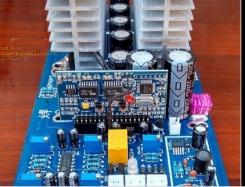
You mean like this one I did yesterday Tinker? Yes Grogster... add tranny and batts and box.... should make a very useful little unit. You may still need to render the 393 inoperable for torroid use..... they don't tolerate spurious pulse waves from the current shutdown system they employ. .........oztules Village idiot...or... just another hack out of his depth |
||||
| Tinker Guru Joined: 07/11/2007 Location: AustraliaPosts: 1904 |
Nah Oztules, mine looks nothing like your idea above  . .
Give me a day or two and I'll post pictures of it assembled but without some of the parts I'm still waiting for. I would imagine there are many ways to do what I mentioned earlier. I see that you now have 5 turns around that ferrite choke, did you notice a worthwhile improvement from the 3 turn version (with obviously thicker wire)? Also, where does that ON switch connect to? Just applying +5V to the temp sense input to activate it? Klaus |
||||
Grogster Admin Group Joined: 31/12/2012 Location: New ZealandPosts: 9307 |
OK then, guys, I will get one of the modules in as linked to by Oz. While I wait for that, I had better make a start on winding up a toroid. Smoke makes things work. When the smoke gets out, it stops! |
||||
oztules Guru Joined: 26/07/2007 Location: AustraliaPosts: 1686 |
Keen to see your unit mocked up then... yes, I use the temp sense on that board for shut down, and the temp probe can be paralleled anyway, so you don't loose function either. The inhibit works fine too, just didn't incorporate it into the board because of the blow ups originally..... gun shy. But later tested it, and it does not cause the torroid to throw up. The 5 turns was because I had under sized wire, so it fitted.... it does help a little, three works fine, 5 works a little better, but not enough to chase unnecessarily. If I had the ecores in abundance, then I would use three turns around two formers.... Yes the transformer is the difference between a solid performer and a wannabe..... "ye shall know them by their weight" ..........oztules Village idiot...or... just another hack out of his depth |
||||
| Page 1 of 25 |
|||||