
|

|
Forum Index : Electronics : Tinkers inverter project
| Page 1 of 2 |
|||||
| Author | Message | ||||
| Tinker Guru Joined: 07/11/2007 Location: AustraliaPosts: 1904 |
Much has been written about modifying a large toroid transformer and using PowerJack boards to make an inverter with real power grunt. I too got the bug and when a forum member located a suitable donor inverter for me (thanks Karl)I jumped to make it mine. The deal was, beside the usual beverage barter exchange, that I remove the heat sink as the inverter's owner wanted to keep that. So when I arrived with my toolbox in hand to take the heatsink off I spotted a little challenge there. The very heavy inverter, sitting on a glass patio table, needed to be handled carefully to avoid wrecking the table. It was a 3Kw Aerosharp unit, these are very well built and make a very good donor for my inverter project. After removing a few parts from the box to get to the transformer I quickly saw that taking the transformer out (to make it to easier get at the heatsink mounting screws)was not something that could be done on a glass table. Removing the 12 or so Phillips heat sink screws with a stubby screw river had it still firmly attached to the side wall of the unit. This is the biggest heatsink that I have ever seen and the Aerosharp people saw fit to also use Silastic to attach it. Oztules describes on his site how he used a 60 ton press to take it off, I did not have one of these handy. So I started with my smallest screw driver, wedging it under the heat sink at a corner where there was a tiny gap. Progressively following this with ever bigger screw drivers, the heat sink was kind of peeled off. The top of the stainless steel box getting a bit dented by this process. But off it was and after packing my treasure in the car I headed to my workshop. 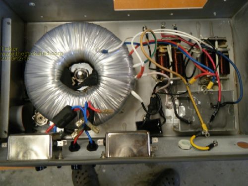
Now everything else still attached in the box was removed to get at that massive toroid. It had a webbing lifting loop at its centre but the toroid would not come off with that as it was stuck to the case bottom with some type of hard gunk. Fortunately the center hole was only filled to the halfway mark so 'persuading' the hard gunk to let go should get the toroid out. 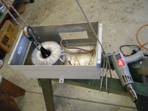
I suspended the toroid by the webbing loop and, using a heat gun, heated the box from the outside around the toroid'd mounting post. Getting it quite hot, but not discoloring the paint, it would not budge. So plan B was called for. I turned the still hot box upside down over a piece of carpet on the floor and heard a 'clunk', the toroid had simply slid off its center black resin support. I guess not much sticks to the mylar tape the toroid was wrapped in. The black resin was still firmly attached to the mounting bolt and to the box bottom. I heated that very hot with the heat gun and then used a pipe wrench to unscrew the resin core from the central bolt, tedious but doable. The now empty box was cleaned up and the dented back bashed flat again with a rawhide mallet and hardwood dolly , it came out as good as new. Next, getting the toroid ready for re winding. Klaus |
||||
| Tinker Guru Joined: 07/11/2007 Location: AustraliaPosts: 1904 |
Part two, readying the toroid. First a test needed to be done to determine the exact turns ratio. 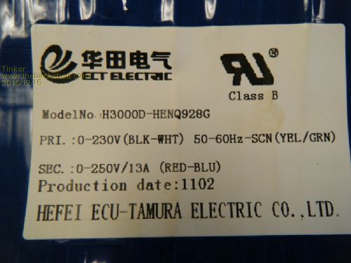
The label on the toroid showed a 230V secondary and a 250V primary winding. I wound on 10 turns of some wire I had handy, connected the multi meter to this and powered the 230V winding up from my Variac transformer. 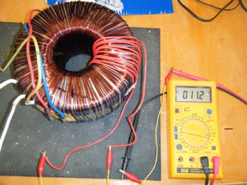
This showed a ratio of 1.113V per turn. The 250V winding was on the outside, 3 in hand of 1.5mm wire, so that needed to come off to enlarge the 60mm center hole. 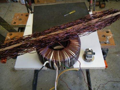
I used a 600mm long shuttle made from a strip of plywood to wind the wire onto. Plywood is kind to the enamel on the wire and 600mm is a manageable size, it could accommodate the 60+ meters of wire from one 'hand'. A mechanical tally counter kept track of the number of turns as they came off, the result showed my 1.113 turns per Volt measurement was spot on. I straightened the wire of each 'hand' as the shuttle was filled so it could be re used for the next 'hand'. My block is not long enough to use oztule's method of pulling the wire straight with the towball, another method in the energy matters forum, suggested pulling the wire around pliers handles did not appeal to me. But I remembered a wire straightening tool I made years ago when I built a full size 3 band cubical quad antenna using 2mm copper wire. 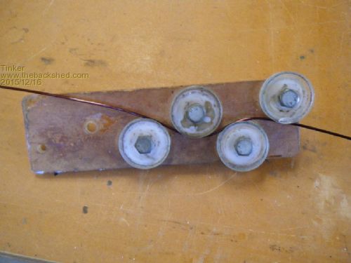
Its made of 6mm acrylic, the wheels have a shallow V groove turned on the rims. Note the odd wheel spacing, this is deliberate. Holding this gadget one way increases the wire bend as it is pulled along the wire, I did this for the first pass. Holding it the other way around decreases the bend as it is pulled along, I used it that way for the second pass. The wire was straight after that. I had only about 30m available to lay out the wire from the anchoring point so it had to be straightened in two go's. The last thing I wanted to do after that was winding the straightened wire tightly onto a bobbin tiny enough to pass through the toroid hole. Using a shuttle for rewinding was also not recommended. So I used an upside down plastic bowl to wind the straightened wire around, I could tie off half the wire on that bowl while I straightened the remaining half. This worked well to keep the wire coils tidy, I labelled each as it was done since they were of slightly different length each. 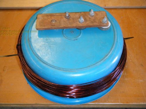
After the 3rd 'hand' was unwound a static screen became visible. This consisted of alfoil tape encased between mylar tape, I unwound this onto a shuttle as I did also to all the mylar tape insulation that came off, to be re used later. I used plywood shuttles around 250mm long for this, made several of them as there was a lot of mylar tape to store tidily. Then came decision time, should I stop unwinding there, add some turns to the 3 in hand secondary now visible (3 x 1.8mm wire) and get on with a new primary? Or continue taking off all the wire? Curiosity got the better of me, I really wanted to see what the core looks like  so I continued unwinding. so I continued unwinding.
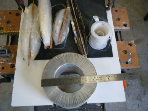
A nice big core with a 100mm hole sat now in front of me, it weighed 11kg. Core dimensions: 190 x 100 x 70mm From that, using a formula buried on page 85 (I think)of the EM forum, I could calculate the Volts for one turn at a conservative flux density. It came very close to 1 Volt per turn so I decided to use that figure for the re winding. The original 230V secondary of 205 turns of 3 x 1.8mm wire added up to 7.63mm sq. My calculated new secondary would have 232 turns of wire so there was not enough 1.8mm wire available for 3 in hand. I decided to use 2 in hand of 1.8mm wire and 2 in hand of 1.5mm wire, giving me a total of 8.62mm sq. A fairly hefty secondary, more copper less heat oztules recommends. Next instalment, rewinding my toroid core will follow shortly. Klaus |
||||
oztules Guru Joined: 26/07/2007 Location: AustraliaPosts: 1686 |
" Curiosity got the better of me, I really wanted to see what the core looks like so I continued unwinding. " Yep..... it's a sickness of some type. Tow ball was only to pre straighten.. then used three bearingssimilar to you.... only I used very much tighter path. Won't be happy until you tell me how tired your shoulders were after unwinding.... The last place I would have ever expected to find one of those 3kw units.... is on a glass table.... there's confidence for you.... I find it a struggle just to lift it up. ...........oztules Village idiot...or... just another hack out of his depth |
||||
| Tinker Guru Joined: 07/11/2007 Location: AustraliaPosts: 1904 |
Part three, rewinding the secondary winding. So I now had 6 coils of enameled wire, some of that was to be used for the rewind. 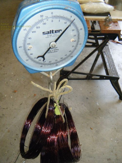
The question was how to go about that task? The bobbin method did not appeal to me, besides I would need a rather long skinny bobbin to accommodate 60m of wire. There must be another way to do this, a straight shuttle kinks the wire too much, what I need is a round shuttle. Hang on, I know just the thing - dashing off to the shops... I came back with this: 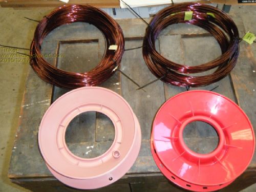
The red reel I got from a fishing tackle shop, the biggest they had at 240mm diameter and it cost less than 5 dollars. Then I went to BCF where I found the pink reel, with its bigger center it looks much more suitable. They had reels with fishing line on and plain ones, the plain ones are much cheaper but even so they were nearly twice the price i paid for the red reel. Anyway, a bit of butchery on my bandsaw gave me this: 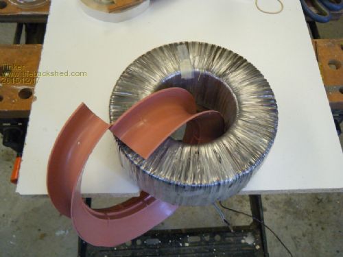
A radial cut got the blade into the center which was enlarged as much as practicable without weakening the rim. The outside diameter was also trimmed down to a size I hoped would hold 60m of wire - could have trimmed off more as it held that amount easily. Next job, place the reel around the toroid and load it with wire, quite easy actually. 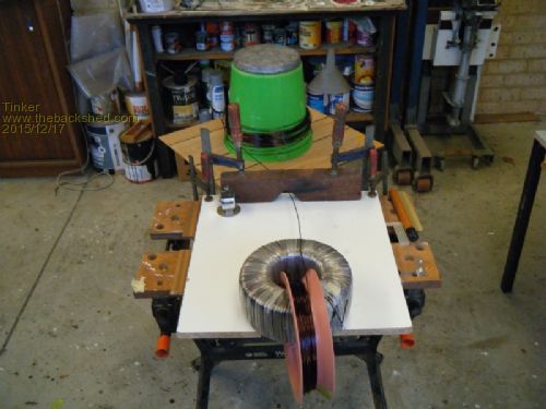
This is how it works, the green bucket on that square sheet of ply sits on a bearing thingie like they use for cake decorating turntables. The bucket had a lump of lead on top so it would not slide off. So I dropped a coil of wire over the bucket which held it nicely. The start of the wire was fed through the wooden guide and hooked into a hole I drilled in the bottom of the reel. The cut in the reel was taped shut with masking tape. All I needed to do was rotate the reel in my hands and the wire magically jumped onto it  . .
Now I had all the wire placed around the toroid, in the correct direction, for winding it. I am left handed so the sloped face of the reel faced to the right and the winding progressed in a clockwise direction around the toroid. I tinned the start of the wire and placed teflon tubing over it as it had to pass through all the following layers of the windings. The start of the wire pointed up on the outside of the toroid core and was held in place with tape. By sliding a bit of wire off the reel rim a loop formed around the core and this was gradually tightened to form a turn. With this method the reel only supplies the wire, it cannot be used to tension the wire. Tensioning was done by grabbing the wire that came up through the center and trying to lift the core up by it, at the same time pushing it with a stick against the core on the inside. One gets pretty strong fingers after doing this 928 times  . .
Anyway, this method of winding is pretty fast and in what appeared to be no time I had a full circle of wire around the rim of the the hole. I did not trace radial lines on the mylar tape, the idea only occurred to me after I finished winding the thing. Lines would have helped a lot, it is easy to lay the wire side by side in the hole but on the outer rim they must be spaced but by how much? its very easy to get the wire there leading or lagging from the radial ideal which compounds on subsequent layers. I tried to wind the wire on two by two a la oztules style but failed miserably. So now I had about 130 turns on the core and as I was going to epoxy and insulate each layer the wire was cut and the end taped on. The wire that was still on the reel was wound back onto the bucket, reversing the loading process. I now could remove the empty reel to give me space for epoxying. For this I turned a 19mm particle board disk to to a tight fit in the center hole and hammered this down to the middle, pressing the wire tightly against the core. That disk was re used for each following layer by turning it to the new size. As the first layer had quite sharp corners for the wire to wrap around and my finger tensioning method did not have the power of a mechanical toroid winding machine, the turns on the outside were now a bit too loose for my liking. Certainly they were refusing to lay two by two. So I did this: 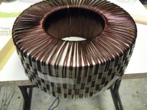
As far as tedious jobs go, this one takes the cake in my book but it did the trick. Needless to say I only did this weaving job on the first layer  . .
A word about epoxying, something I'd done lots of building my wooden boat. There are many types of epoxy, all formulated for different applications and having different mixing ratios. I prefer the 2:1 ratio boat building epoxy, its easy to mix and it does not cure rock hard. Wood contracts and expands a little with temperature changes (and so does copper wire) and we do not want the epoxy to crack as the rock hard curing type would eventually. For the small quantities required I weigh the epoxy resin and hardener, its far easier but not exactly correct as epoxy resin & hardener is supposed to be measured by volume. But its pretty close with the stuff I use and I never had a failure. 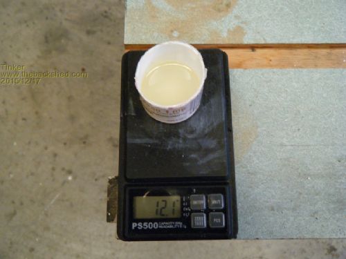
I use a cut off plastic pill container and a paddlepop stick for mixing. If the mixing stick is left standing in the epoxy dregs in the pill container, to go off, it then can be pulled out with the epoxy leftovers attached and the container re used. To apply the epoxy I use a 12mm brush, the cheap kind that come in packs of 3. They can be washed in acetone and re used a few times, I went through 2 brushes doing the whole rewind. The epoxy was applied in two go's on side at a time and taking great care not running any onto the plywood disk jammed in the center of the hole. This disk was knocked out after epoxying the first side. After this job one overlapped layer of mylar tape was wound on. I used cello tape to hold the start of the tape as this kind of tape was also used on the original. The shuttle method of stowing the mylar tape pays off here, the tape comes off the shuttle nicely if its fed through the hole correctly, it twists if not  . I had plenty of practice to find this out. But its no big deal if twists develop, just tie off the tape temporarily with masking tape and untwist the shuttle. . I had plenty of practice to find this out. But its no big deal if twists develop, just tie off the tape temporarily with masking tape and untwist the shuttle.
I found the best way of tightening the mylar tape is not by pulling on the shuttle but by sliding the tape around the winding between thumb and index finger. It can be wound much tighter without breaking it this way. Now the reminder of the 'hand' needed to be wound on. The wire I had wound off was not long enough for this (it only did 205 turns originally) so I wound a new bundle of recovered of wire onto my reel. They were soldered together so the join was on the outside. After pre tinning each end and feeding a bit of glue lined heatshrink tube over the wire then tying the wire ends, overlapping side by side, with thin copper wire the job was completed by soldering and heat shrinking the joint. The winding continued, there were now less turns remaining for a close spaced circle on the inside so I spaced the wires there a little to have the 232rd turn finishing about 3cm away from the start. One 'hand' done, three to go. I used the 1.8mm wire for the first two 'hands' and the 1.5mm wire for the last two. This worked out well so I could complete each 'hand' in two layers with the beginning and end located at the same place around the outer circumference of the core. Each layer was epoxied and mylar taped, this extra work paid off as the toroid was absolutely silent, not even the faintest hum, when I tested each 'hand'. 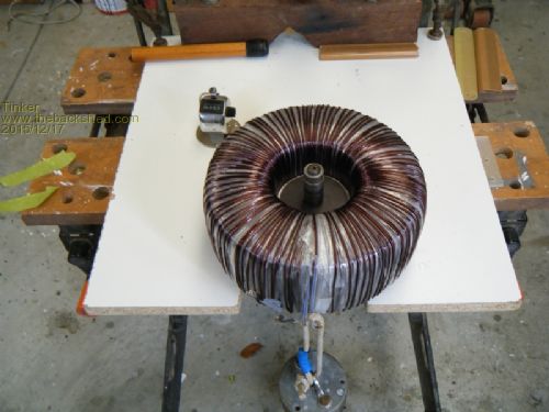
The magnetising current came in surprisingly low at 36mA with 230V applied. 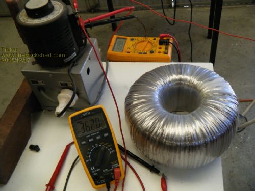
I used a variac transformer for all my tests, this let me use an AC multimeter on the milliamp scale without wrecking it by the inrush current on switch on. Each 'hand', of course, was tested for identical voltage and magnetising current to the other 'hands'. Now all that was left was to re wind the static screen on. It was originally terminated to the earth wire by soldering but this connection came off easily without heat, aluminium does not take solder very well. Its quite tricky to get the mylar insulation off on one side as the alu film within is very thin. I exposed about 15mm and taped tinned copper braid (with alminox connection paste in between) to the alu - no soldering. 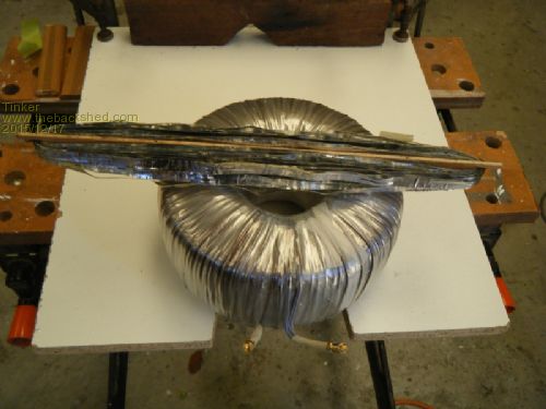
I then re checked the idle current of the windings, a shorted turn in the alfoil screen would increase that but all was well. 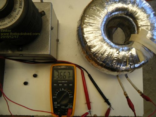
To be continued. Klaus |
||||
oztules Guru Joined: 26/07/2007 Location: AustraliaPosts: 1686 |
You have even more patience than me. It turned out fine from the looks... like the fishing reel, although no good for me as the core I use is far too long...( 2 or 3 stacked up) but fine for yours from the looks. Should give you years of silent power.... keep up the good work. I have too many high power inverters now.... but I will still give the eg8010 a shot... soon I hope. ..........oztules Village idiot...or... just another hack out of his depth |
||||
| Gizmo Admin Group Joined: 05/06/2004 Location: AustraliaPosts: 5078 |
Thats a work of art Klaus! The best time to plant a tree was twenty years ago, the second best time is right now. JAQ |
||||
| gpalterpower Senior Member Joined: 19/07/2009 Location: AustraliaPosts: 175 |
Nice job there Tinker.  Love your innovative fishing reel for winding. Wish I thought of that when winding mine. Inexpensive too! Love your innovative fishing reel for winding. Wish I thought of that when winding mine. Inexpensive too!
Marcus if it aint broke dont fix it!! |
||||
| Tinker Guru Joined: 07/11/2007 Location: AustraliaPosts: 1904 |
Thanks guys, I appreciate your approval. Keep watching for the next installment. Klaus |
||||
| Tinker Guru Joined: 07/11/2007 Location: AustraliaPosts: 1904 |
Part four, rewinding the primary. With the secondary completed the hole in the toroid's center had shrunk to 65mm. A bit smaller than I had hoped but then I will have a better & quieter transformer when it is finished. With the hindsight of my experience I would suggest to anybody starting with an identical toroid transformer to do only a partial rewind. Taking off all the 3 hands of the outer 250V winding to start with. Then removing the static shield to get at the 230V winding. Then either sourcing some 1.8mm wire and adding 27 turns, 3 in hand to the 230V winding. This would give a 7.63 sq mm secondary winding. Or re using some of the 1.5mm wire and adding 27 turns, 4 in hand, to the 230V winding. Job done, the 3 or 4 in hand could possibly be wound on simultaneously with my fishing reel method as there would be very few turns on it and little chance for the wire tangling. Anyway, I now had the task of fitting 29 turns of a decent size primary through that 65mm hole. I was aiming for 50mmsq at least. Not enough room for using 2 in hand of 25mm sq welding cable. Alternatives, 16 in hand of 2mm diameter wire - too hard for me. I visited the local motor rewinders and asked if they had any bigger enameled wire or even square wire, no, 2mm was the biggest they used. But he mentioned a place just down the road where they make square and rectangular wire. There I was told they make any size enameled wire I wanted, minimum order was 400m. This a lot more than I required and I then explained what I wanted it for. They were most helpful and told me the have leftovers of odd sizes they sell once a month to a scrap dealer for $8.- a kilo and I could have some for the same price. They had a size I could use and I went back home to calculate how many kilo's I need. About 7.5kg would do nicely and they told me it would be ready the next day for pick up. So I cam back with this: 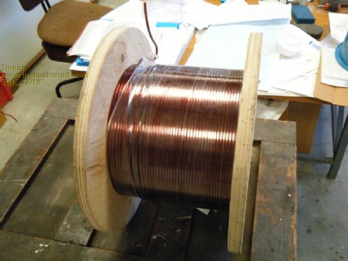
I was very happy to part with $60.-, the wire even came on a nice sturdy new reel. Its size was 3.2 x 4.5mm, giving me 14.4mm sq. So just 4 in hand would make a decent 57.6mm sq primary. Now the next challenge, how to wind that stuff around the toroid? Turned out easier than I thought at first. I did not want to straighten out this wire for measuring a 'hand' so I used my wind around the plastic bowl method, a calculated 13 turns would be long enough for the first hand. I used the same method to place this wire around the toroid, without the fishing reel, as the wire was stiff enough to support itself. 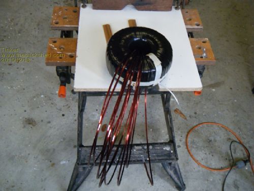
First the start end was tinned, easier to do now. then, starting with the other end, the wire was poked up the toroid hole and a good size loop formed which was masking taped to the end. It was easy now to unwind the wire from one hand and wind it to a coil in the other hand that formed around the core as I progressed. Now came the tricky part, how to hold the tinned start in place. 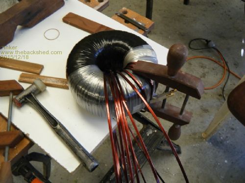
I used a special wooden clamp that I made when I built my boat. The winding job became easier once a turn or two was around the core. To tighten a turn I held the wire coming up the hole under tension and tapped the turn around the core with a plastic faced hammer, this formed the turn nicely as the corners were by now fairly rounded. 29 turns with a space in between each now formed the first 'hand'. I had run out of mylar tape by then so I used 20mm heat shrink tape (the black stuff on the next picture), This tape had been waiting for years on my shelf for just such a job. Its quite thin but sadly nowhere near as tough as the mylar tape was. 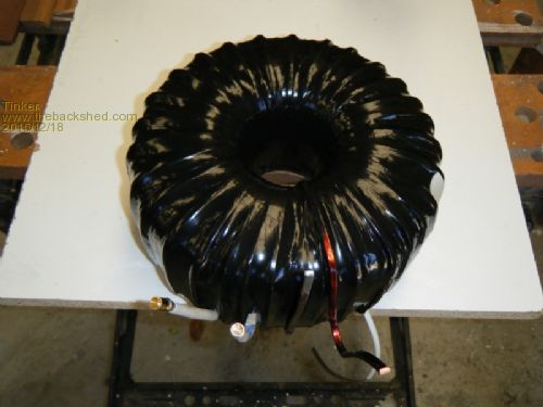
Then the second 'hand' was wound on, somewhat closer spaced in the center to end up at the same place. 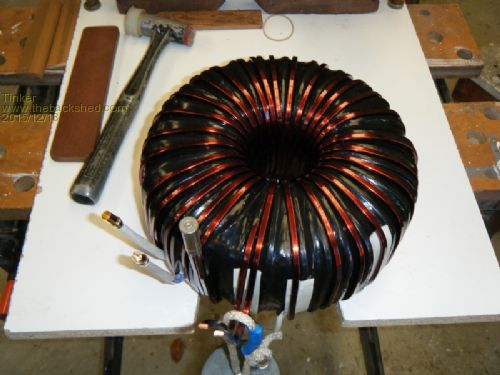
By the time the 3rd 'hand' was wound on even a tightly spaced winding in the center overran the full circle of the core so I had to over wind the last two turns to end up at the desired spot. I had run out of the black heatshrink tape by then so I used herringbone pattern fabric tape. This is very strong and locks very securely onto the wire once coated with epoxy. 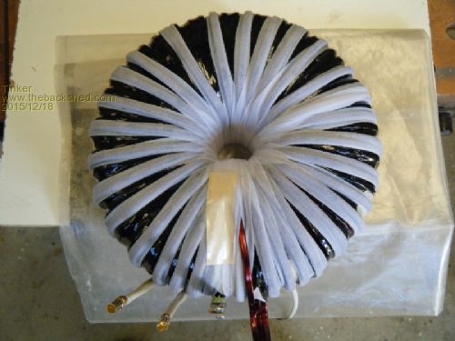
Now I had a dilemma, the center hole had shrunk to about 25mm diameter. Can I fit 29 turns through there? A calculation gave me 34 possible turns so I started the 4th 'hand'. After about half the turns were on it became obvious this was not going to fit and I had to unwind it again. 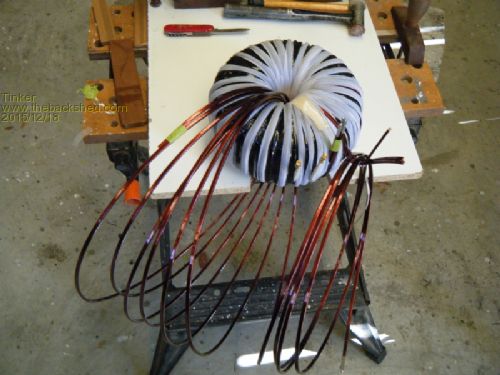
Now there were about 12m of somewhat kinked 3.2 x 4.5mm wire on my floor, I did have some some use for that later on but first had to solve the 4th 'hand' problem. I really wanted a primary of >50 mm sq, 3 in hand only gave me 43.3mm sq. So plan B was called for. I went back to the wire makers to see if they had some smaller stuff that I could use for the 4th 'hand' winding. They had 2.5 x 3.7mm wire of which I bought one kilo. This added 9.25mm sq, giving me a total primary of 52.45mm sq and achieving my target. The smaller wire was wound on then and it fitted nicely  . There was even enough space left for the center mounting stud which was a great relief, as this simplified the toroid mounting a lot. . There was even enough space left for the center mounting stud which was a great relief, as this simplified the toroid mounting a lot.
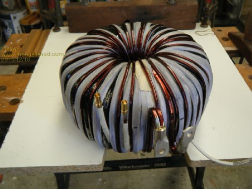
The finished toroid transformer weighed in at a hefty 20 kg. 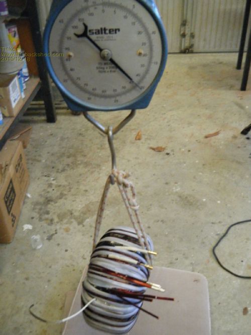
I was very pleased with my chosen winding method, especially after reading about the struggles some had with stiff round cable. Lastly, here is a picture of some of the tools I used for the rewind job. I even made a special wire bending tool after seeing the one Gizmo made, it was never needed. 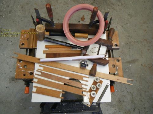
To be continued. Klaus |
||||
| Tinker Guru Joined: 07/11/2007 Location: AustraliaPosts: 1904 |
Part five, winding the ferrite efficiency multiplier. With the big transformer now finished, another, very important, winding job had to be done. I had read about the struggles many had trying to wind a miserly three turns of cable, 25mm sq or so, around the little bobbin that came with the ferrite E core. I had about 10m of 3.2 x 4.5mm enameled wire (the discarded 4th 'hand' of the primary winding above) to play with plus some wire left on that big reel. How hard could it be winding a tiny coil with that stuff? Well, it was a lot harder than I thought  . .
I started making by a winding jig. 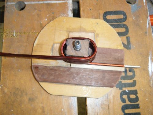
And this produced a few failures before I managed to make a usable coil. 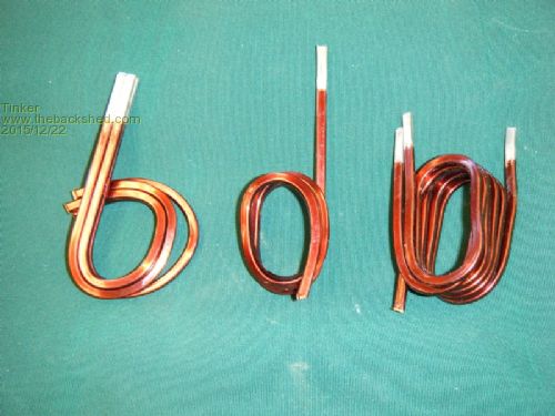
There are two ways to wind this rectangular wire, on its wider side or on its narrower one. Since I was aiming for 4 in hand (57.6mm sq total), winding this on the wide side there was space only for 3 1/2 turns on the 40mm long bobbin. BTW, I did not wind any of my coils directly onto the bobbin - its much to fragile for that stiff wire - but modified the bobbin beforehand with my Japanese pull saw this way: 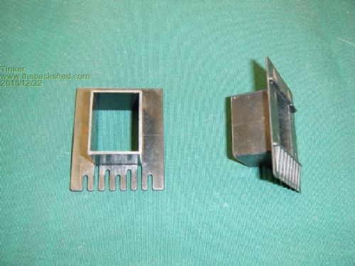
I now could use the same bobbin for as many coils I wanted to make. Anyway, the 3 1/2 turns coil looked like this: 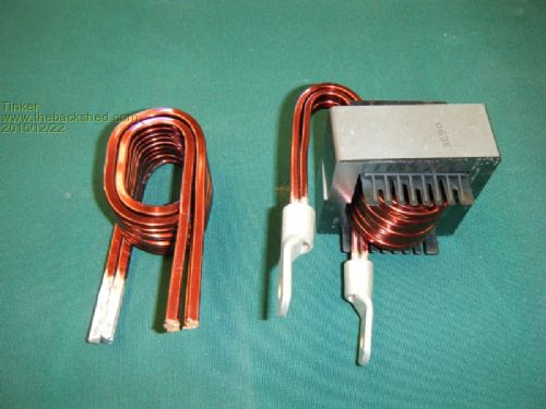
The one on the right that is. I did not like it much as the ends emerge at opposite sides and one needed a U turn to suit my installation. The coil on the left is a 5 turn, the wire wound on its narrow side. What a struggle that one was, the wire really did prefer to flip sideways at each corner and only a movable cheek plate, backed by a powerful spring, on my winding jig kept the 4 wires aligned. This coil required some 'persuasion' from my press to have its sides flat enough to pass into the E core, it fits nicely now but the modified bobbin no longer fits. The problem was the wooden jig, it deformed a little at the corners. What I needed was a much sturdier jig, one that preferably had no corners. So I made this: 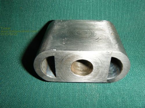
This center fitted into an all metal jig and was used on my lathe to wind the coil I'm happy with. 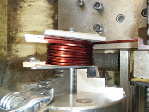
The 3.2mm wide wire matched the 4TPI feed of the lathe nicely. I turned the chuck by hand via an adjustable spanner, the motor spun far too fast for this delicate winding process. This is what I ended up with: 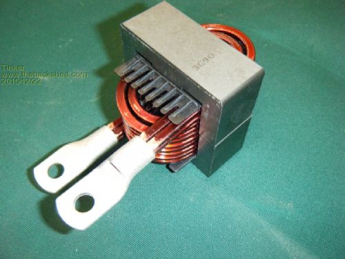
5 turns of 57.6mm sq wire, beat that! Now I'll have to find out if it all was worth the extra effort. To be continued. Klaus |
||||
oztules Guru Joined: 26/07/2007 Location: AustraliaPosts: 1686 |
Not much more I can say... other than WOW..... It is nice to see a different approach. Your workmanship is very good... makes mine seem a bit neanderthal really...... Should be a very sturdy unit. There is no doubt... twin and tripple cores are easier to wind.... think I will stick to that.... much more real estate to play with. ............oztules Village idiot...or... just another hack out of his depth |
||||
| Tinker Guru Joined: 07/11/2007 Location: AustraliaPosts: 1904 |
Yes oztules, twin or triple cores would be far easier to wind but first one must acquire these extra cores - you seem to have cornered the market there  . .
Anyway, on with my inverter conversion progress report. Testing the ferrite E-core efficiency multiplier. Well, the results were interesting, surprisingly so... I should mention here that as yet I do not have my house battery bank connected to 48V, I am still waiting for the new outback solar controller - held up at customs apparently. So, using 4 smallish sealed 12V batteries in series for my testing hook up I got these bench top results: No E-core connected had a 3.5A current draw, that is just the PJ modules and the toroid, nothing else connected. Using my 3 1/2 turn coil on the E- core the current dropped to 0.51A. I found a very thin gap space (0.02mm) worked best with this coil - used video tape as this was the only stuff that thin available. No gap gave a worse current. Using my 5 turn coil on the E- core had the current drop to 0.45A. Not a lot of difference which should make all you guys who managed only 3 turns onto that tiny core happy  . .
For that 5 turn coil a much thicker gap (0.1mm) worked best. Actually, 0.06mm to 0.1mm gave very little difference. For 0.06mm one sheet of that clear plastic document laminating envelope was the source. I also had a small roll of 0.1mm clear plastic film so I used that - it looked sturdier. I tried to take some pictures of my oscilloscope screen, very difficult with my digital camera. there was a lot of high frequency hash on the toroid primary winding with no ferrite E-core in the circuit. With the 5 turn coil the trace on the primary looked like that: 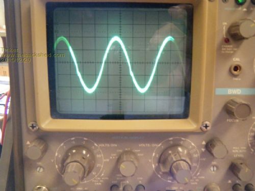
The secondary looked very much similar, a higher voltage of course. So, while I'm happy with my 5 turn coil I now have these two on the right available as freebies: 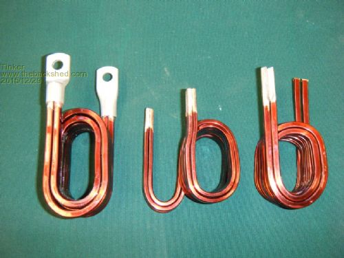
Both are usable but would require insulating with that mylar tape so the ferrite core does not rub on the enamel. A 50mm sq cable lug would fit on the ends for a neat termination if the corners are filed round. The 5 turn coil requires finishing one end but its already epoxied to hold its shape. The 3 1/2 turn coil needs epoxying to keep it rigid (wants to unwind a little like a spring). The coils are located at my place in Perth, WA, PM me if anybody wants them, at over 50mm sq wire they would be hard to beat. Next, putting it all together. to be continued... Klaus |
||||
| Tinker Guru Joined: 07/11/2007 Location: AustraliaPosts: 1904 |
Putting it all together. The Aerosharp 3KW inverter came in a nice enclosure which I planned to re use. Now, oztules in his blog describes the difficulty he had with working the 2 mm stainless steel this enclosure is made of and he was not wrong there. I decided to make use of most of the existing openings in this box so the large rectangular one, where the original gigantic heat sink fitted was the place to mount two of my fans. 80mm fans were almost the right width so I used that size. First I made an alumunium cover plate to close the whole opening, this had 2 circular holes cut into it for the fans. These were the exhaust fans. So I required two more 80mm holes for the air in fans on the opposite side. There is very little room to locate parts in this box once the big toroid was fitted. The PJ heatsink module had to be aligned across the narrow side of the box so one of the air in fans could blow air directly into the heatsink tunnel. The only way to cut a 80mm hole into stainless in my workshop was to drill a series of small holes (about one hundred) inside this circle first. These were then enlarged so that the rims almost met. Then the remaining metal bridges were cut with a small cold chisel. Lots of work gave me two fan size holes with very ragged edges. Smoothing this with a file soon became too tedious, it would have taken me a week for each hole. So I used the die grinder I happen to have and managed to dress these holes neatly at the cost of two finger type grind bits. Stainless is definitely outside the range of a battery powered drill, a decent workshop with a pedestal drill is required to work it. I cut the central mounting stud for the toroid short and fitted a threaded bush there, the stud was going to be too short anyway and being able to insert a longer one after wiggling the heavy toroid into place (it has less than 5mm clearance at some places) was a distinct advantage. 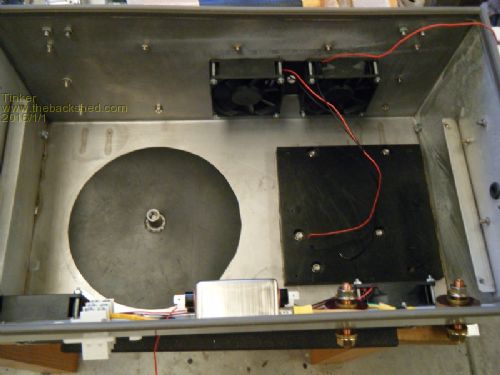
The black circular disk was cut from 1mm neoprene rubber to cushion the toroid. The other black plastic is 16mm thick to allow the original welded in mounting posts to be re used. This was for the PJ assembly. 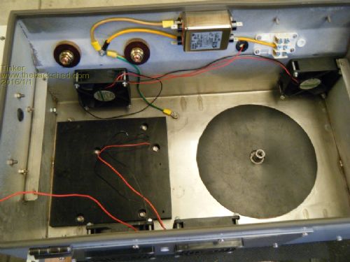
The central hole at the underside of the toroid was prepared the following way: A 13mm fiberglass dowel was the max size that fitted into the hole, this was waxed well and inserted so it was vertically aligned. Then a little silastic was dribbled to the narrowest part of the hole to seal it around the dowel. Next a mixture of epoxy and Q-cells (a lightweight filler I had at hand) was poured into the remaining 'crater' to fill it level with the toroid windings. Lastly a short piece of PVC tubing the size of the threaded bush was slid over the dowel and the epoxy mix was let go hard. 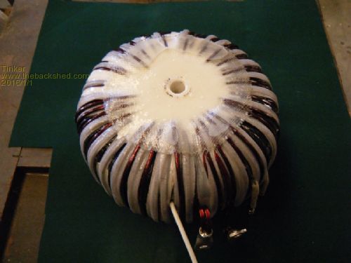
After that the dowel and the short PVC tube could be pulled out and this made a snug fit over the threaded bush when the toroid was later lifted into the box. I epoxied a disk cut from heavy weight glass cloth over that surface to spread the pressure on the 3 or so windings that were higher than the rest of them. I had some ss 10mm allthread from which I made a longer mounting bolt. This was covered with glue lined heatshrink tubing except for the places at each end where the thread was required. Then this bolt was waxed at the heat shrinked part and screwed into the bush with screwlock securing it there, after the toroid was inserted. Now the top 'crater' could be filled up to top level with the same epoxy/ filler mix. On top of this was placed a 50mm diameter plywood disk, to spread the compression load when the nut on the ss bolt was tightened later. 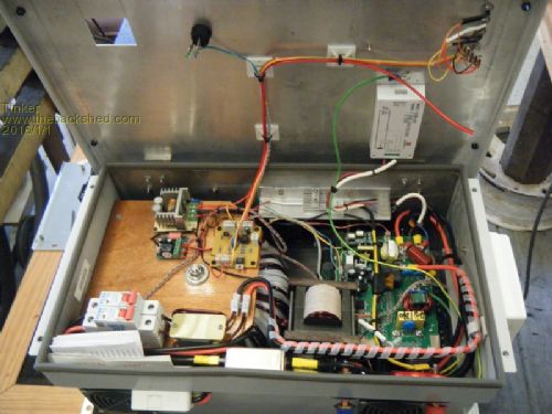
As mentioned, the connections to the PJ module were very tight and too short for cables so I made copper bus bars from 1mm x 30mm tinned copper sheet, two in parallel to carry the current. 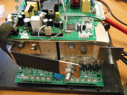
The heat sinks had an extra 70mm fan fitted to one end, this is the 3 wire fan that the controller board apparently required. But I found the board would fire up without any fan plugged in on initial testing. 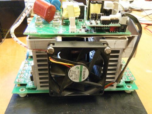
By now the inside of the box were pretty crowded. The final installment, load testing this inverter, will follow once I have re configured my battery bank and solar panels for 48V. Klaus |
||||
| yahoo2 Guru Joined: 05/04/2011 Location: AustraliaPosts: 1166 |
Thanks Klaus, I am hoping the trace on the scope is going to be more of the same when you load test it, maybe a bit of a flat top on the wave with some capacitive loads. Some stainless grades can be tricky, they can work harden as you deform it, plus the chromium content is tough to start with, high speed steel cutting tools are not quite up to the job. I'm confused, no wait... maybe I'm not... |
||||
| Tinker Guru Joined: 07/11/2007 Location: AustraliaPosts: 1904 |
Hi Yahoo2, I'm expecting no flat topping up to at least 3Kw loads  , surely, after all that effort I put into this thing I deserve a little reward , surely, after all that effort I put into this thing I deserve a little reward  . .
Anyway, load testing is not far off, my solar panels were re connected to 48v pairs today and the battery bank wiring is well under way. Yes, having built a sailboat and done most of the stainless work myself I'm familiar with the stuff but had thought they would use a lesser quality ss on this housing. Fortunately the lid is made from 2mm aluminium which is a breeze to work by comparism. Klaus |
||||
| Tinker Guru Joined: 07/11/2007 Location: AustraliaPosts: 1904 |
Testing the inverter. Finally all was in place for a decent load test of my creation. I had a fully charged 48V, 200Ah LYP battery bank and an Outback flexmax60 controller connected to 1.6KW of solar panels feeding the bank. Starting slowly with a small load (~100W) all went well, the oscilloscope trace showing a nice sine wave. Next 500W (immersion heater) and all's well powered up. Then a heat gun, #1 setting (1000W) OK but at #2 setting (2000W) the fault light came on and the inverter shut down. What's going on?? More testing showed that 1200W was the most it could handle before shutting down. So a lengthy process of finding the problem followed and the cause, while being simple, eluded me for a while.  . .
What happened was that somewhere in oztules notes I had read that a 5K6 resistor across the temperature sensor of the controller board should make the 3 wire fan come on. Well, I never managed this fan to get going and forgot about this resistor. Fortunately it was just poked down the back of the little 2 pin sensor plug so getting this resistor out was a quick job. What a difference, the inverter now worked as expected, no, far better than I expected or even had hoped. A few test results: At 990W load the efficiency was 83% At 3866W load the efficiency was 90% At 4257W load the efficiency was 86% So this thing runs most efficient at around a 4Kw load. Certainly more than I had expected. The above was done with resistive loads (kettles & heat gun) The oscilloscope trace at 4257W load looked like this: 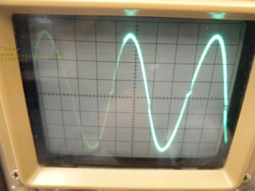
No flat topping - sorry about the poor picture but the battery drain was more than 90A at this test so I hurried things up a bit. Curious how much power I could get from this inverter I plugged in my 2 kettles and an abrasive cutoff saw. No problem at all running all that, a load of just over 5Kw and still no flat topping on the sinewave trace. This thing might run a 6Kw load at a pinch, I was not game to try as 5Kw is more than I would ever ask from this unit. So it paid off to overbuild it in the copper winding size, the boards are good for 8Kw (Chinese Kw  ) anyway. ) anyway.
BTW, the standby power was 32W with no fans running but everything powered up. I guess a fair bit of that goes to the 48V to 24V DC to DC converter I use to supply power for the 24V fans. A couple more pictures: 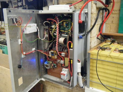
As can be seen, I hinged the front panel which makes it a lot easier to gain access to the innards. I used offset hinges, ordinary butt hinges would require a spacer block to allow for the lip on the lid. This is how it looks on the outside: 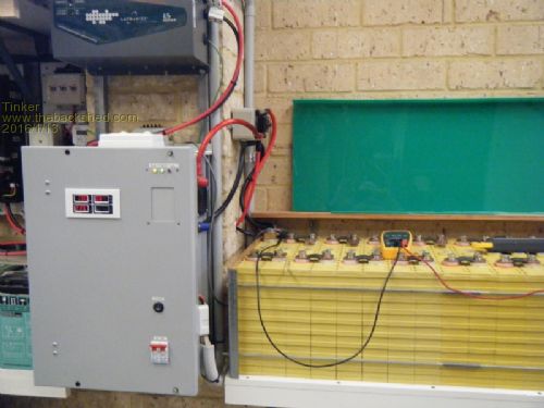
Two digital displays are still missing (slow e-bay), a battery voltage and a temperature display. Both will go on that dummy cover where the original Aerosharp display was. Klaus |
||||
oztules Guru Joined: 26/07/2007 Location: AustraliaPosts: 1686 |
It is capable of extraordinary short term power with very minor distortion, seems to start anything too. Cooling will be problematic for your physical design when pulling 4kw for longer periods, but this will not happen often I suspect. Good to see another successful unit. Mine runs high power for extended periods, but that particular one is built in a much bigger enclosure, with a lot of natural convection in the design, and the bigger heat sinks.... 4kw cont is not a difficulty. PJ is on a real winner here, but they seem determined to stuff it up where possible. Well done with it Tinker, your attention to detail is better than mine. Im guessing Glen is becoming more comfortable with his unit by now too. They work much better for the money than they deserve to. ..............oztules Village idiot...or... just another hack out of his depth |
||||
| Tinker Guru Joined: 07/11/2007 Location: AustraliaPosts: 1904 |
Thanks oztules, for yours and Glenn's very informative posts which gave me the confidence to go ahead with this project even though I knew little about how inverters worked. Now I know a lot more  . .
It really was a fun project and the "attention to detail" is how I was trained to do my work. Back in them days (1960's) we even had to align all the slots in all the external screws (no Philips head screws back then) for a neat appearance. You are right about the cooling, the fans came on often on this 30 degree day with just a 200W fridge load cycling on and off. Once I get my temperature gauge installed I will closely observe how the unit handles higher loads for extended periods and twiddle the fan controls accordingly. Yes, it was a tight fit to get everything into that neat cabinet but I did not have a bigger one and not much room to put one either. Klaus |
||||
| KarlJ Guru Joined: 19/05/2008 Location: AustraliaPosts: 1178 |
WOW If i had have known how much work was involved i probably wouldnt have got you the Aerosharp! good news is i have 3 more and 2 of the 1.5kW versions if anyone feeling motivated for similar torture. RE the other little E cores -bigger than most i throw away each day but perhaps i should stat saving them for you? incredible effort and 5/5 stars for effort and result shows it. i'm currently building a powerwall (built nearly 3 x 1kWh 18650 bricks so far) which should be enough for my peak shaver. I have a spot welder too if you need it for a similar project. You clearly have inverter-itis -apparently curable I have battery-itis ATM (literally 500+ cells i have welded so far) and of course panel itis - incurable too Karl Luck favours the well prepared |
||||
| Tinker Guru Joined: 07/11/2007 Location: AustraliaPosts: 1904 |
Update: My inverter has been running for a little while now and never missed a beat. So I decided a longer term load test to see how the fans cope might be useful. Today being a warm day, it was 35 degree C in my shed when I started this test. The temperature inside my inverter cabinet was around 35 degrees C, which is when the fans switch on. This happened each time one of my fridges cycled on. So I connected a 2.4Kw fan heater and watched what happened. The inverter efficiency was 94% with that load which looks good to me. The cabinet inside temperature climbed very slowly with the fans running, creeping up to 42.7 degree C after 30 min. It looked like settling thereabouts as the temperature increase was slowing down a lot. But as the draw from the battery bank was around 47Amps and only half of that replenished by my solar panels I terminated my test at this point. 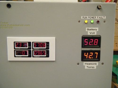
Now the cabinet temperature started dropping again, returning to 36 degree C after a further 15 minutes. The fans stopped then. Later in the day the ambient temperature climbed to 35 degree C and the cabinet had 40 degree inside with the fans running all the time. The load was just two fridges cycling on plus some 60W standby from other things connected. So it looks this inverter will do the job nicely, I have no plans (nor battery capacity) to run high loads for extended times. But, that malaise is still with me: 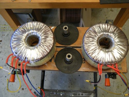
so there might be a stacked core version being built soon  . .
One thing puzzles me though and I might ask the experts here: From other build posts I gather that the 3 wire fan is essential to be connected to the PJ control board. Well, I bought a 12V 3 wire fan, it worked when testing it on a 12V battery, and connected it to the control board as shown on the diagram on Gizmo's project. This fan never ran at all after that so I unplugged it and removed it from the cabinet. It now appears faulty (does not run on a battery)??? Strangely my inverter does not care if that fan is connected, it supplies power faultlessly. I did attach the PJ temperature probe to a chassis screw as its place on the heatsink is now occupied by my own fan control temp sensor. The probe needs to be connected to the PCB or its goes to fault mode. Klaus |
||||
| Page 1 of 2 |
|||||